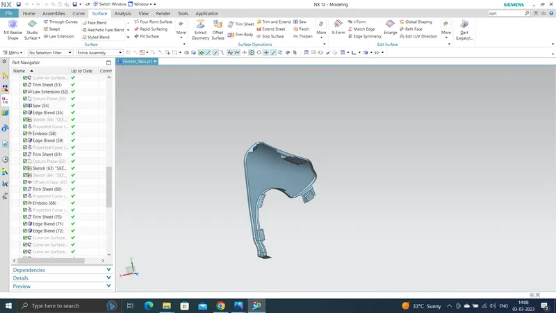
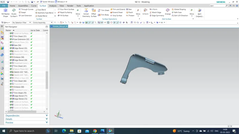
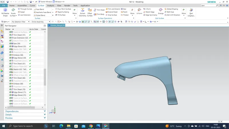
Fender Design
Aim:- To design a Front Fender
OBJECTIVE: To design a Fender mounting on the given model by using Master sketch by considering the safety and manufacturing feasibility for possible mounting region.
Introduction:
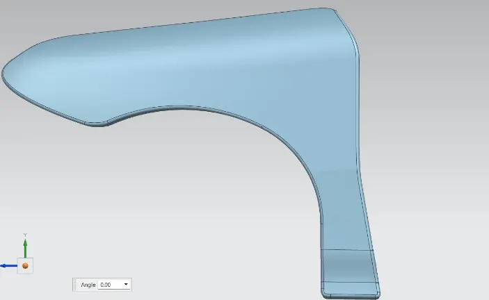
Fender: Fender is the US English term for the part of an automobile that frames a wheel well. Its primary purpose is to prevent sand, mud, rocks, liquids, and other road spray from being thrown into the air by the rotating tire.
When the vehicle is moving, tyres pick up syones and others and hurl them in all directions. Fenders are basically present to prevent any injuries to pedestrians and contain the motion of these particals. Most passenger automobiles have four fenders, one over each wheel. For vehices with a narrow car body that exposes the tire, the fender is an exposed curve over the top of the tire. For wide body vehicles that cover the tire, the fender forms the wheel well surrounding the tire, and is not directly visible from above the car boy.
More elaborate designs include fender skins for enclosing the outside edge of the wheel well, and stylized pontoon fenders for exposed fenders.
Need of Fender:
- It is designed to provide resistance against wind, muds, and roadside particals.
- It is the sheet of metal covering of the car.
- Fender has a plastic part called Baffle or fender Liner which fits underside the fender to protect the metal from corrosion by stopping the flow of mud and water inside from different road conditions.
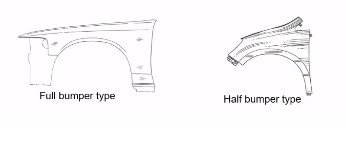
There are 2 types of fenders.
- Full Bumper Type
- Half Bumper Type
Full Bumper Type: Full Bumper Type is not used now a days because it requires large size of balnk to produce the part and it occupies more space.
Half Bumper Type: Half Bumper Type Half bumper is used because the waste of material is less & can produce two fender at the same time by slightly increase the raw sheet. and to reduce the weight & cost mostly bumper fender are been produced.
Design:
Master Sketch:
Data Given:
- The drip area should be made after leaving the space of 150mm from front for headlight mounting and before 200mm from cowl area and 10mm distance left from Engine room.
- The angle from top of flange is 40 degree and 8mm long is created to stop the view of Engine Compartment.
- The radius values of Drip area at dfferent stages.
Mountings:
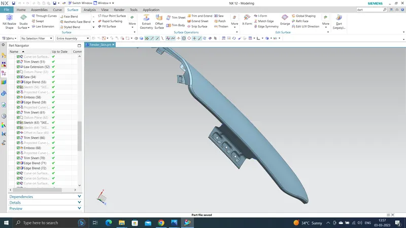
- Drip Mounting Area
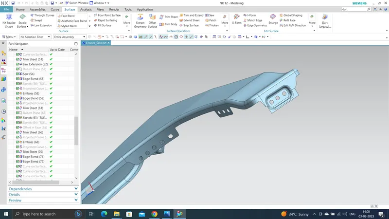
- Sill Mounting Area
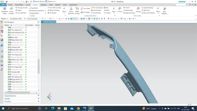
- A-Pillar Mounting Area
- Bumper Mounting Area
- Baffle or Linear Mounting Area
Drip Mounting Area:-
Sill Mounting Area:-
A-Pillar Mounting Area:-
Bumper Mounting Area:-
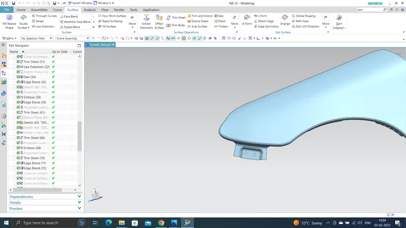
Baffle or Linear Mounting Area:-
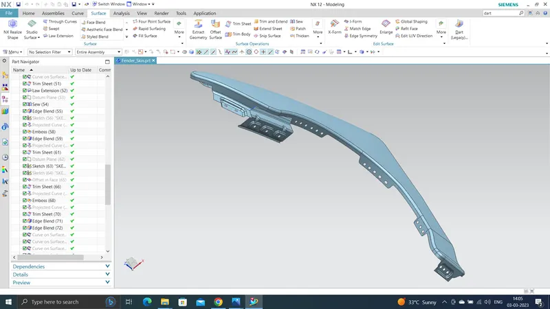
Conclusion:
Designed the Front Fender in NX application with proper mountings by using the Master Sketch and Design Parameters.