Fender Design
OBJECTIVE
To design various mounting points on the fender, according to the design parameters.
INTRODUCTION
Fender
Fender's purpose is to prevent rocks, mud, sand, liquids from being thrown into the air or on to the pedestrians by a rotating wheel. Fender is made aerodynamic in shape to reduce the air drag.
There are two types of of fenders
1. Full Bumper Type.
2. Half Bumper Type.
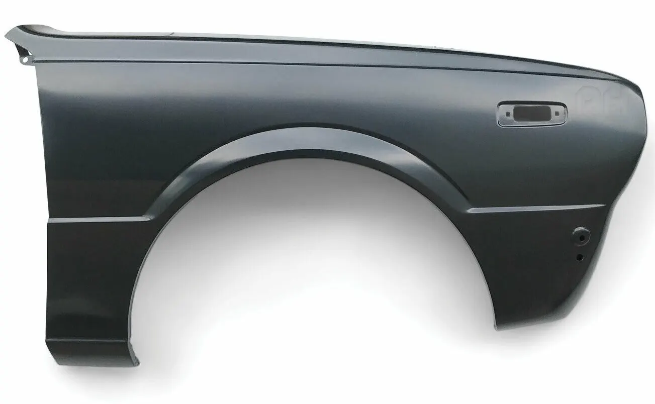
Full Bumper Type
Full Bumper type
This type of fender is used in olden days, it is no more in use due to its heavyweight of the structure and consumes more (RAW MATERIAL) in manufacturing.
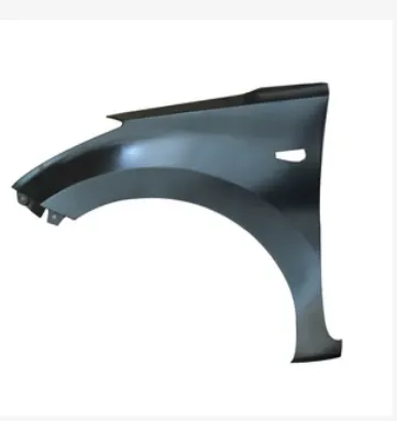
Half Bumper Type
Half Bumper Type
Half Bumper Type fenders are widely used now, due to its mini size and the scrap or wastage is less compared to the full bumper type.
DESIGN METHODOLOGY :
GIVEN DATA :
MASTER SECTION
Manufacturing process
The manufacturing of the fender majorly involves these operations.
1.Embossing
2.Bending
3.Cutting and Blanking
Embossing
Embossing is a metal forming process for producing raised or sunken designs or relief in sheet material using matched male and female roller dies, theoretically with no change in metal thickness, or by passing sheet or a strip of metal between rolls of the desired pattern.
Bending
Metal bending is a process by which metal can be deformed when applying force to the subject, which causes it to bend at an angle and form the anticipated shape, which often results in it being in a ‘V’ or a ‘U’ shape. This is done through the application of force on a workpiece. The force on the work piece can be mechanical, pneumatic or hydraulic.
Cutting and Blanking
Cutting processes are those in which a piece of sheet metal is separated by applying a great enough shearing force to cause the material to fail.
Blanking is a steel manufacturing process in which a flat, geometric shape is created by feeding a coil of sheet metal into a press and die. In this process, the blank is punched out from the large metal sheet.
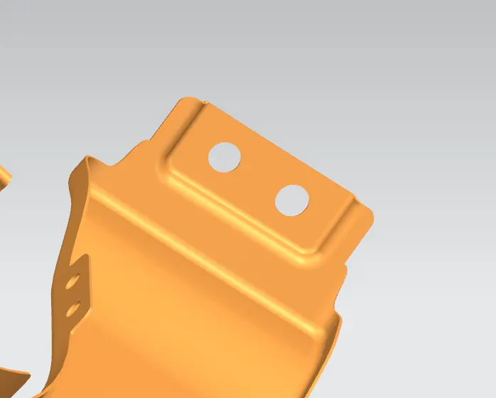
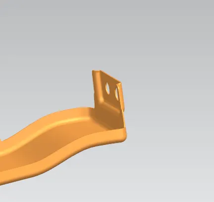
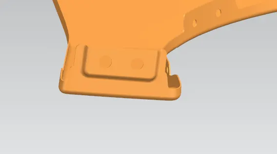
Fender is mounted basically on 5 important regions. They are
1. Drip Area
2. A-Pillar Mounting Area
3. Sill Mounting Area
4. Bumper Mounting Area
5. Baffle Mounting Area
Drip Area
The area at which the fender gets attached to the engine housing through fasteners. It is the major mounting for the fender. Mountings at the drip area are designed leaving a clearance of 200mm from the back of the fender for the cowl setup. And clearance of 150mm from the front of the fender for a headlamp housing unit.
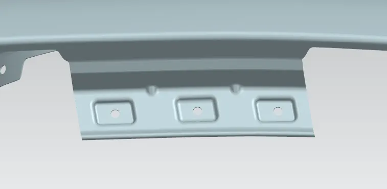
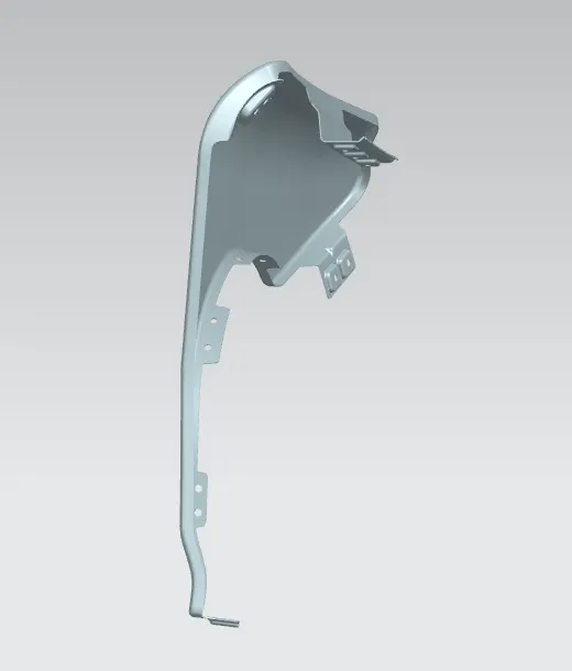
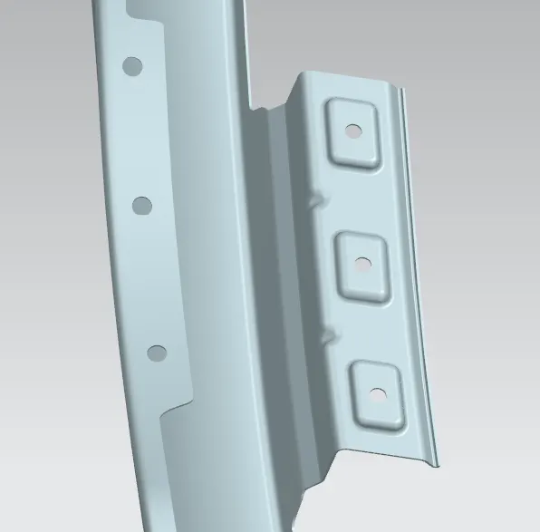
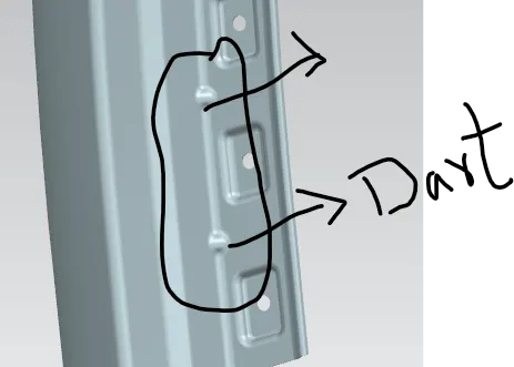
Darts are provided at the bends to stiffen the sheet metal at that region.
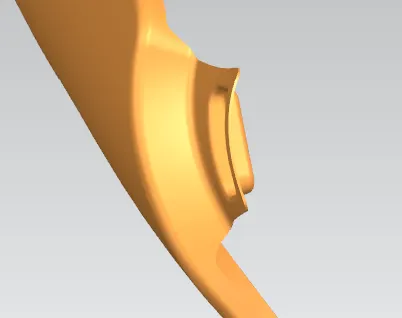
A-Pillar Mounting Area
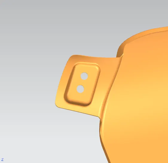
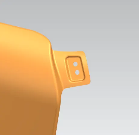
This Mounting region is located near the cowl of the vehicle where the fender is fastened with the bottom edge of the windshield. This mounting is covered with the side rear-view mirror.
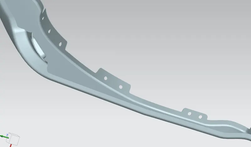
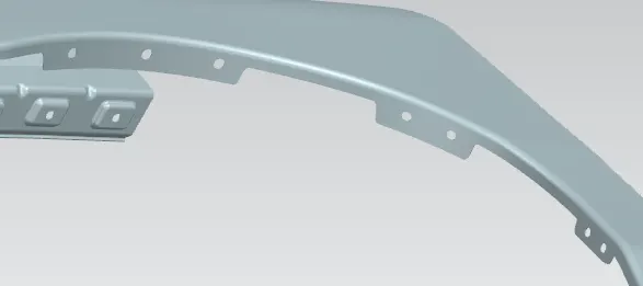
Sill Mounting Area
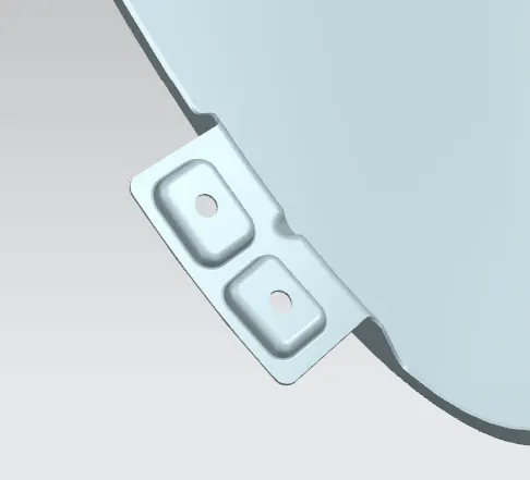
The area at which the bottom of the fender gets connected to the floor near the bottom edge of the door. The Embossed sill mounting of the fender is attached with the fasteners.
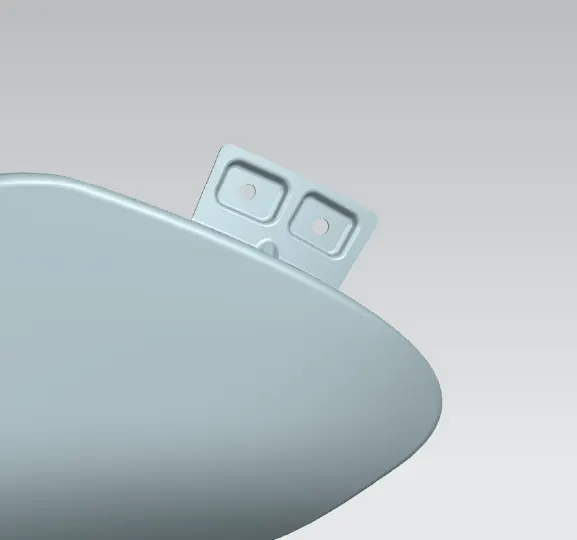
Bumper Mounting Area
The bumper mounting region is located beneath the bumper. The fender gets attached before the installation of the bumper. After fixing the fender with fasteners the bumper will cover the bumper mounting.
Baffle Mounting Area
In this region, the baffle gets installed to the fender with the help of clips which holds the baffle with the fender along the wheel arch.
APPLYING OF THICKNESS TO THE SURFACE .
The thickness of 0.75 mm inward on the final sewed surface of the fender to the sheet metal parameters
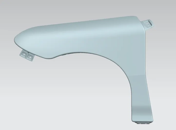
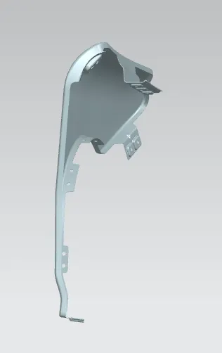
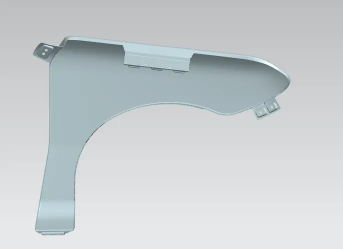
DIFFERENT VIEWS OF FENDER :
CONCLUSION
The Fender is designed with the necessary mounting points considering the design parameters.