Fender Design
Fender Design Using NX Cad
1. Introduction
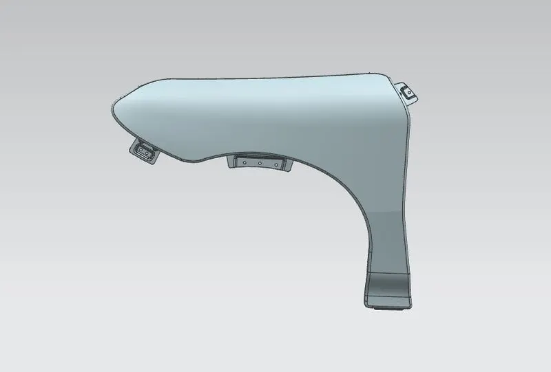
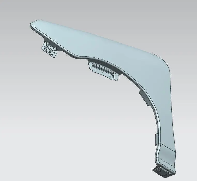
The fender is the side frontal portion of the vehicle, which protects the pedestrians from small dust particles. There are five mounting regions in the fender
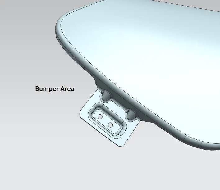
- Bumper mounting
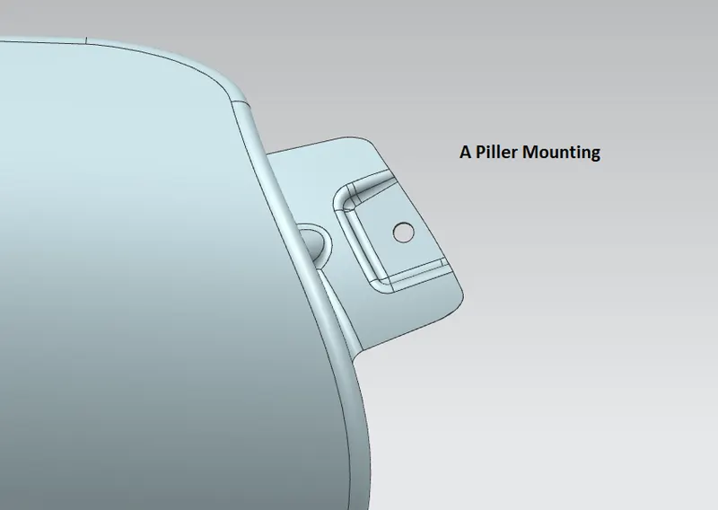
- A-pillar mounting
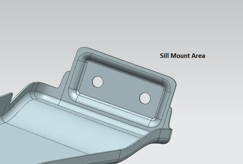
- Sill mounting
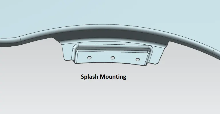
- Splash mounting
- Drip mounting
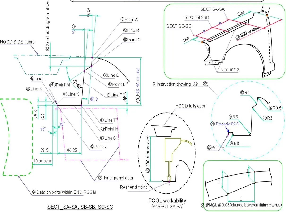
The master section of the fender is given as
PROCEDURE TO DESIGN FENDER IN NX CAD
The fender master section is obtained from the styling department. The mounting regions have to be designed in NX CAD.
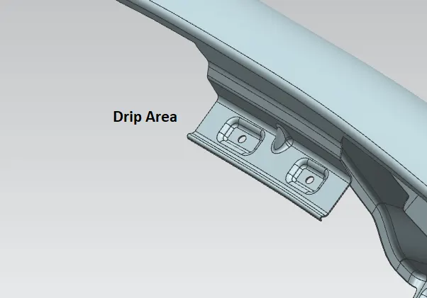
As given in the master section, the drip area in the fender is designed.
- Offset the curve with a 5 mm distance on the surface of the fender using OFFSET CURVE ON SURFACE command.
- Draw the curve on the surface where the A-pillar has to be mounted using CURVE ON SURFACE command by taking the end of the curves as intersections. So a smooth curve can be drawn, but for dimensioning purposes, the sketch can be drawn and projected.
- Draw the curve near the sill mounting.
- Using the TRIM SHEET command, cut the extra sheet between the A-pillar mounting and sill mounting.
- Now, from the car front bumper side with a 10 mm distance, draw a DATUM PLANE with a curve on the surface selection and 150 mm distance create a datum plane.
- The same create a datum plane from the A-pillar mounting with a 200 mm distance.
- Between these two regions draws two curves using CURVE ON SURFACE command.
- Trim the sheet from the bumper mounting and the A-pillar mounting to get the drip area.
- Using the LAW EXTENSION command, create the drip area the same as given in the master section.
- Use FACE BLEND and EDGE BLEND commands to make the smooth curves.
- For mounting, the screws flat surfaces are required. For the flat surface, create a datum plane with DATUM PLANE command and choosing three points on curves.
- Draw a rectangle and a circle. The circle should be 5 mm, and there must a 5 mm clearance surface around the circle.
- project the curve on to the surface using the PROJECT CURVE command.
- Use EMBOSS command with end cap option as datum plane at an offset of 3.5 mm and 15º draft angle (a minimum of 7º is required).
- Trim the sheet to form the holes.
- For smooth curved edges, give an edge blend of a 3 mm radius for all the embossed edges.
- Ribs can be created on the mounting region were ever required to increase the mounting strength. DART command is used to create the ribs.
- The same procedure is followed in all the mounting regions.
- The fender is thickened with 0.75 mm using the THICKEN command.
- For signal lights, the hole can be created on the fender panel.
CONCLUSION
From the fender design challenge using NX CAD, the design offender and drip area are learned using different commands. The A-pillar mounting, spill mounting, splash mounting, bumper mounting is designed.