Fender Design
Aim:
- Follow the given Master section to create the Drip Area
- For the Sill, Bumper, Baffle(Splash), and A-Pillar mount create your own design according to the Engineering standard that you learned.
- Prepare a report with all the relevant images included for the mounting points created.
Given master seection for Drip Area
Procedure:
- Save the file as Catprt.
- Rework on the Class A Surface.
- Create Tooling Axis.
- Create Flange mounting area cut in reworked Class A Surface.
- Create flanges for every seperate parts like, Drip area, Bumper molding area, Class A Surface Area, Sill, and Wheel Arch area.
- Create Surface in part using thicksurface operation.
Fender:
Fender can be seen in all vechiles. The primary purpose is to prevent from hitting of stones, sand, mud, liquids and other spray from being thrown from tire. And it looks aesthetic. It can be seen above the wheel arch area. Fenders near the front wheel are manufactured seperately while the rear fenders are manufactured with the body itself.
Fender types:
1.) Full Bumper type:
- Full bumper type is old car model type.
2.) Half Bumper type:
- After 1990's they started using half bumper type, because of cost reduction in the point of manufacturing and in point of size reduction. This type is easy for maintainenance.
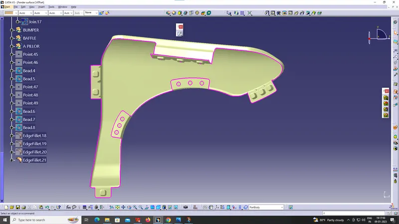
Fender consist of five mounting areas, They are:
- Drip mounting area.
- Bumper mounting area.
- A - pillar mounting area.
- Sill mounting area.
- Wheel arch mounting area.
Drip mountiing Area:
It is a BIW attachment feature is to connect with car body. The mounting area is designed according to the given master section. In the master section they had given several norms to create in that 150 mm and 200 mm gap is mandatory to follow. The 150 mm gap is given for the clearance of Head light mounting area and the 200 mm gap is given to clearance for Cowl area, it is nothing but the wiper mounting area.
Bumper mounting area:
It is also given for the attachment feature for fender to bumper. This will consist of emobse for screw to make the fender more rigid.
A - pillar mounting area:
It is given for the attachment feature for the fender and A-pillar surface. This will consist of emobse for screw to make the fender more rigid.
Sill mounting area:
It is given for the attachment for the fender and Sill mounting area. This will consist of emobse for screw to make the fender more rigid.
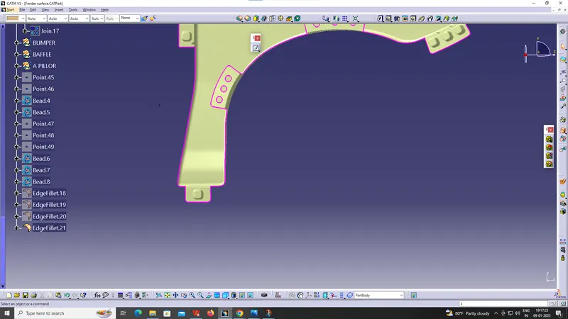
Wheel arch mounting area:
It is given for attaching the fender with wheel arch mounting area. This will not consist of emobse since the attachments are between BIW and plastic trims and the attachment feature. The attachment feature used here is push clips.
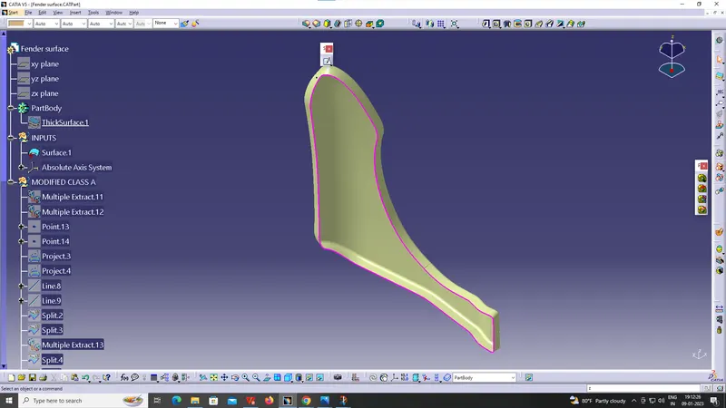
Class A Surface:
The Class A finish is the highest quality finish Microform Precision can provide. It is often specified for high visibility surfaces such as control panels, front covers, etc. in which the Customer demands the highest quality appearance.
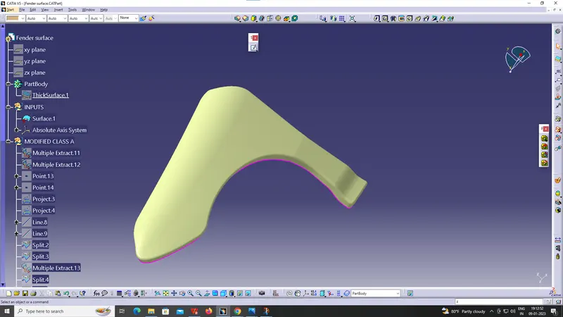
Reworked Class A Surface
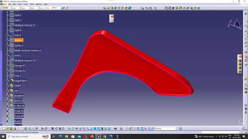
Flange mounting Cut:
All the mounting sketch had been taken and the class A surface is splitted according to it.
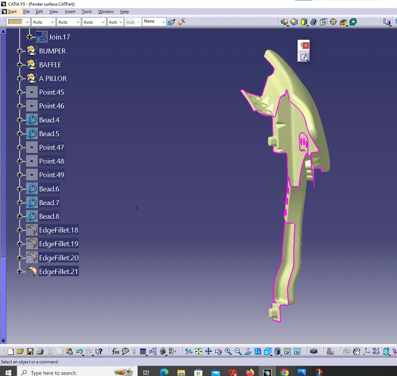
Draft Analysis:
Draft analysis in sheet metal is differ from the plastic. In sheet metal 7 to 10 deg draft angle should maintain, so that it is easy to do ejection.
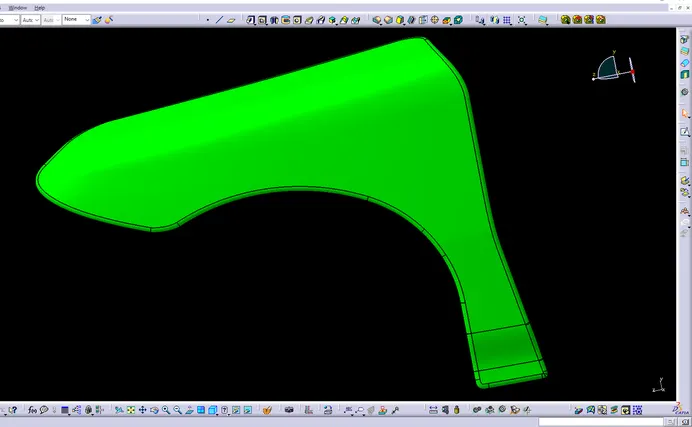
Solid Surface:
Here the surface is thickend using the thicksurface option with thickness 0.75mm.
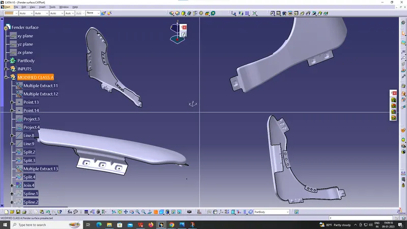
Tree Structure:
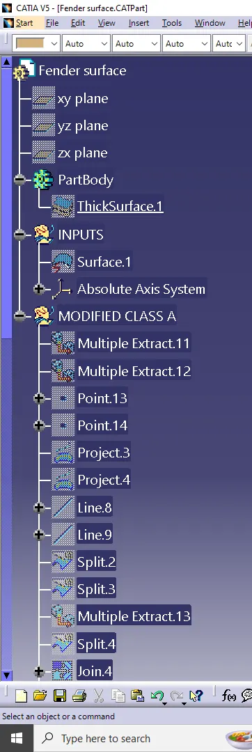
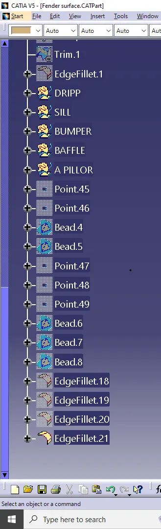
CONCUSION :
Finally design of fender is done with the help of CATIA.V5 software by following the master section