Fender Design
FENDER DESIGN
#Software Used:-
1.CATIA V5
#Introduction:-
Fender is the part of an automobile that frames a wheel well. Its primary purpose is to prevent sand, mud, rocks, liquids and other road spray from being thrown to the air by the rotating tyre and cause injuries to the pedestrians.
#Mountings:-
There are generally 5 mountings on a fender-
1. Body
2. A-Pillar
3. Sill
4. Cowl
5. Drip
These are joined using fasteners and not brackets, thereby improving the NVH Factor (Noise, Vibration, Harshness).
#Designing:-
Drip Area
It is the most important mounting unit of a fender. It is connected with the engine compartment and therefore a lot of design constraints are to be followed while designing the drip area.
It should have sufficient clearance from the front and rear end of the fender to accommodate the Cowl mounting region and the Headlamp housing unit respectively as shown in the figure.
Fig 1- Master Sketch
The Master Sketch provides the linear and angular measurements for designing the drip mount after taking into considerations various factors like Hood opening, Tool workability, aesthetics (since Fender is a styling surface), Spring Back effect due to exceeded length etc. 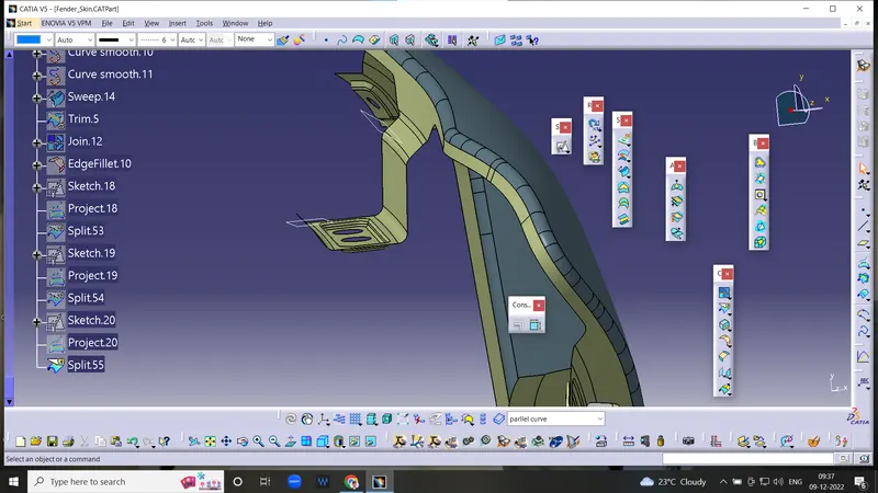
Drip area
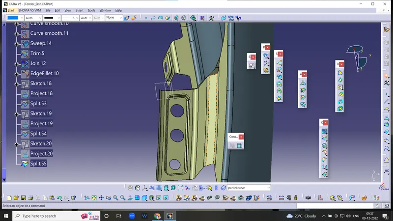
Drip area
Other Mountings
The mountings for Bumper, A-Pillar, Flush and Sill areas were designed according to the engineering standards by providing adequate relief for producibility.
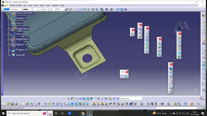
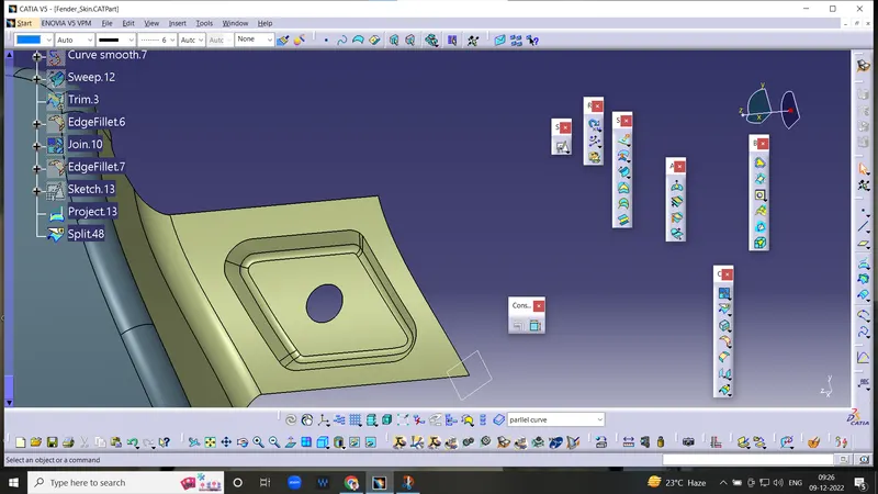
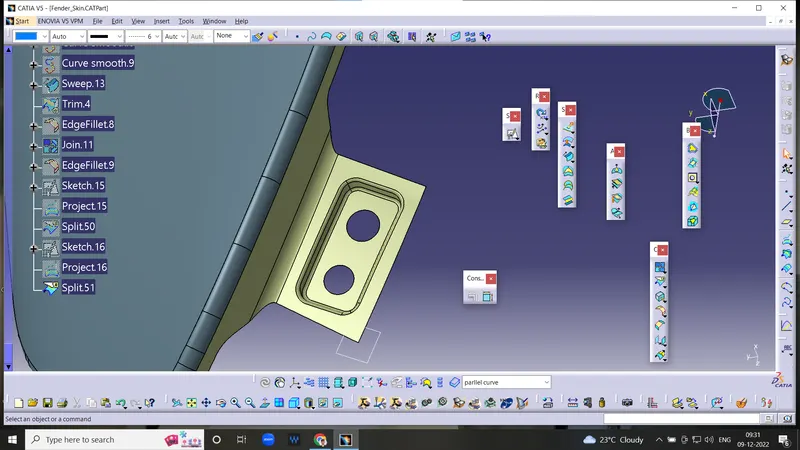
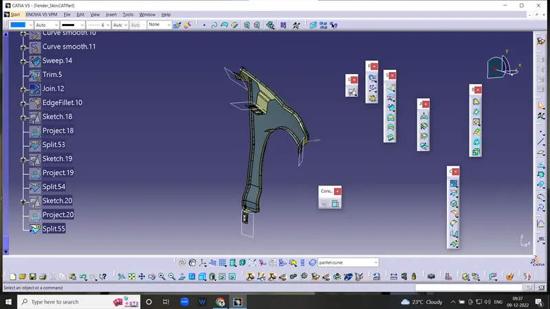
Embossing was provided on the mountings to strengthen them during fastening.
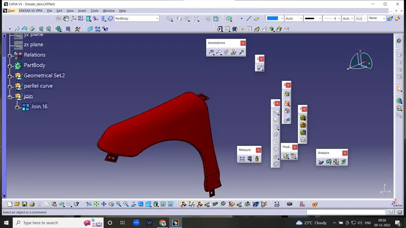
Commands under Generative Shape Design Workbench of CATIA V5 were used extensively for various operations along with Part Design Workbench commands. Industry standard Fillets, reliefs and design constraints were applied to ensure producibility of the part.
#Conclusion:-
Thus the Drip Area, Bumper mount region, A-pillar mount region and Sill mount area were designed for the Fender from the styling surface provided.