Fender Design
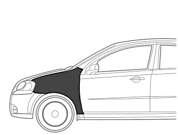
FENDER :
REAR :
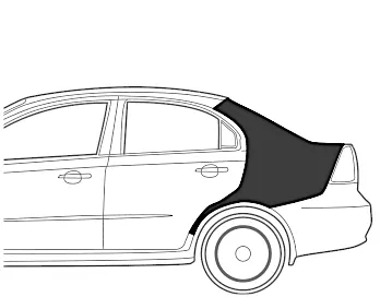
- The sbove picture shows the front of the back fender of the car .here was csn see front an the back fender ,arked in the image .The front fronder is desinged along with the body pillers. front fender are more importent than th back frenders. most of the car have four fronder s are four wheels. some vechicles with wide of the fender will cover over tyre for vechicles with wide body the fender will cover over the tyre. In this fender will from a wheel wellover the tyre
- The size of the will be smaller than that wheel well up beause if its not like that then the tyre suspension trvel wan`t be happening blockingthe full range of motion of te suspension and allowing the tyre move freely inside the weel well u and down with out tuching the inside the wheel well faces.
TWO TYBES OF FENDER
- FULL BUMBER TYBE
- HALF BUMBER TYBE
FULL BUMBER TYBE :
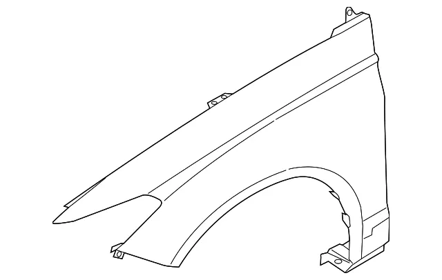
- In the tybe more material is need for the design the fender. hence more wastage of material. this design will also add to the weight of the car as ther is more sheet matel is used in this design.
HULF BUMBER :
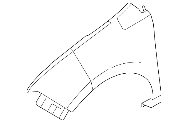
- In this tybes of material is used t desing the part less wastage of the materials that leads to less cost this design will allow to usage morer plastic on the bumber so the weigt of the car canbe redused to a certin . this tybe of fenders is now widely used intheindustry.
MANUFACTURING PROCESS :
- Just ilke the all the sheet metal parts raw materials under grow various manufacturing process to gain its purposefull shape and size basic manufsacturing involed in manufacturing of BIW are .
BLANKIGNG :
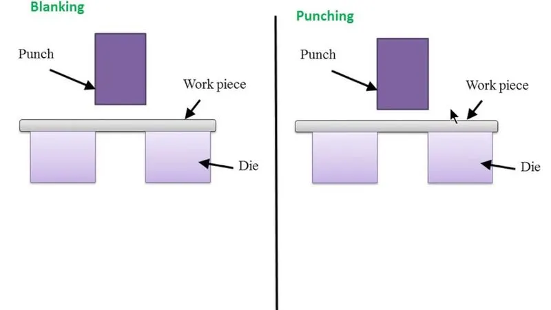
- Tihis process for cutting the nsheet metal in to desired size for a particuler compont .
DRAWING / FORMING
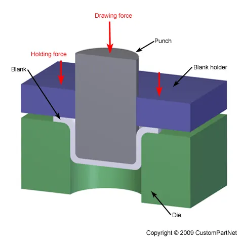
- This process is responsable for shaping the sheet metal according to the componet.
HEMMING :
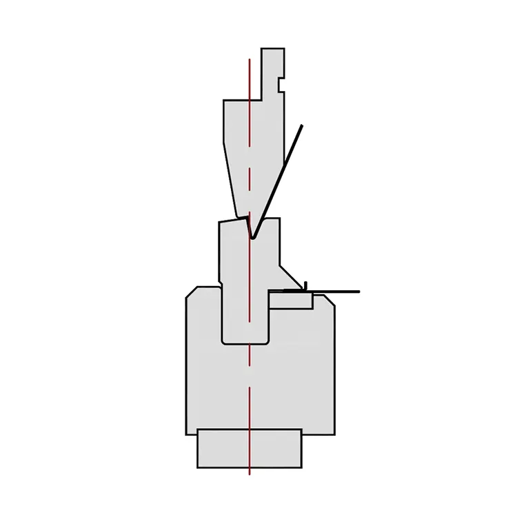
- is a process of joining to flat sheet metal by floding its edges in a particiler angle. this is done places whwre welding and other joing process are not an opation .for example. class A and the inner of the automotive parts cannot be jined by welding due to aesthetic reasons. in that case hemming is used.
MASTER SECTION
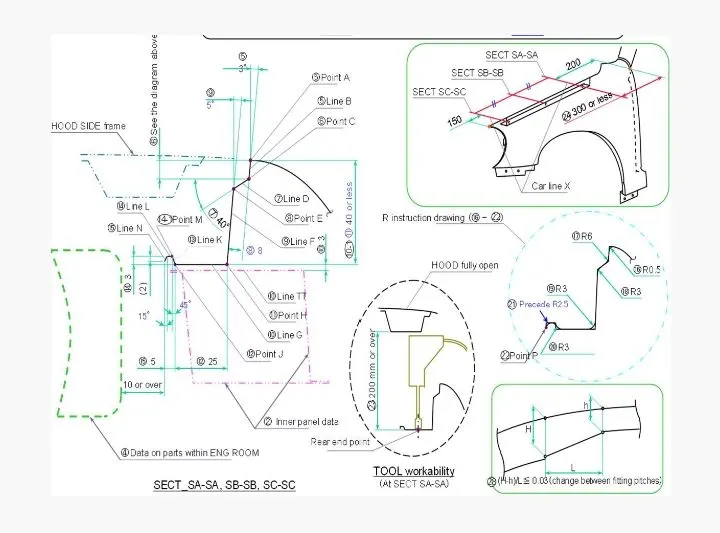
- The above shoen mastere setion along for the trip area mounding and a class a surface is given as input to begin with be rest of the mounding desing condersation are assumed based on this master section and also conesdiring the industry standards.
- from the maste we can the see information no how to desing the drip area mountings for the fender. in the master section it is given that the drip mounding shutbe located at 150mm from the bumber and should maintan a gap of 200mm from the a piller also the deatails on the fillets are given in the master section for the drip area.
MOUNTINGS :
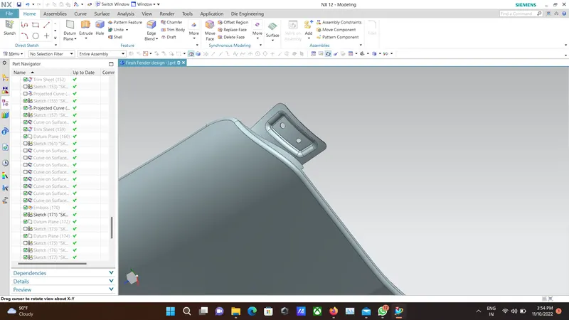
- Then fender get attached to the car like all over body part of the cars for mounding the fender to the body of the car .we abviously need differnt mounting for fender . these mounting are purpose fully designed areas of the car which the different sides for fender going to get mounted nhere we are the mounding for following regions of the fender.
- DRIP AREA
- BUMBER AREA
- SIL AREA
- BAFFLE AREA
- APILLER AREA
DRIP AREA
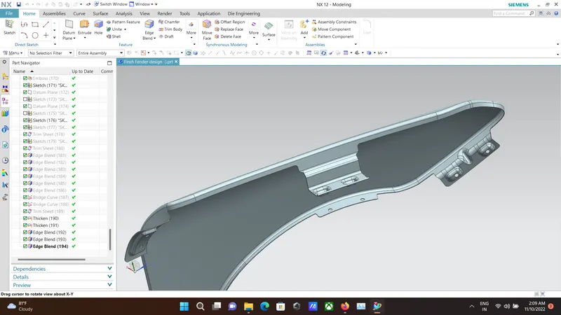
- Drip area located at the enfine compartment of the car. this is the primary mounting of the fender and given priorty as well beacuse well of the face that this mounting has more length on the fender According to the master section given the drip area mounting is created with a minimus distance of 150mm fron the front region of the engine bay and distance of 300mm is kept from the back region of the engine bay.The mounding and the fender connection should be an approx .distance of 10mm .as shown the masster section the length from point A to point H (length of the mounding )shuld be less then 40mm to avoid the spring standerd as the length of the mounting is more its better to give more reinforcement like mounting filltes are given an purticlur mount at particlur placess according to the master sectionalso minimum fillets are given at undefined for better manufacturabilty.
BUMBER AREA
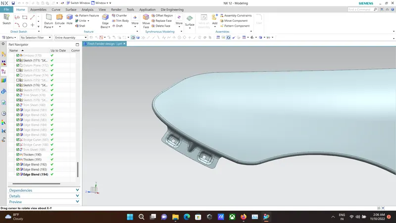
- bumber area as the name is for mounting the frnder into the bumber portion of the car This is a small mounting compared to the drip area mounding .Here we can give one (OR) more weld bolt hone for mounting fillets and other design consideration are done similary as the drip area mount.
SIL AREA
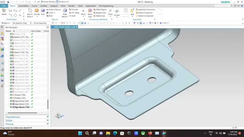
- This area comes between the bottem portion. of the fender and the bottom ptotion of the car body. This mount is curculer for a frim mounting of the fender to the body this mount is the smallest mount in the fender fillets. and other design consideration are done similary as the area mount.
BAFFLE AREA
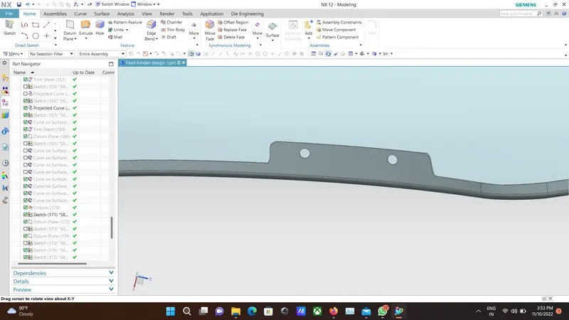
- This mounting is very curcial for keeping the NVH down inthe car .this mounts come near the wheel arch protion of the car. This mount can be designed in two (OR) more section to give the assembly a firm fit. Mostly the design of this mounting can done as a simple extension from the fender part.
A PILLAR AREA
- This mount connects the fender with the body (OR) the a- piller together. This can be done with a single (OR) a double bolt. but for a fit. more then single bolt is recommended.
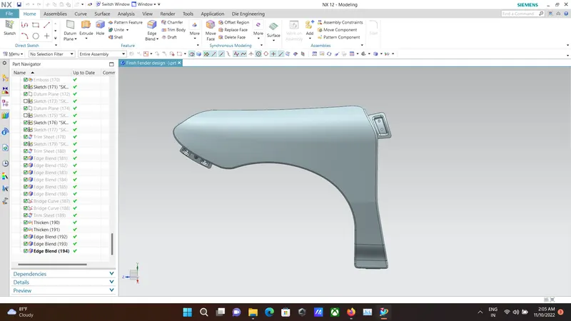
COMPLETE FENDER
CONCLUSION
- For project i was able to design the mounting points for the given fender design according to the master section and design the mounting points in such a away that it was hghly manufacturing by following the industry standerd parameters.
THANKYOU