Fender Design
FENDER.
Fender is the part of an automobile, motorcycle or other vehicle body that frames a wheel well. Its primary purpose is to prevent sand, mud, rocks, liquids, and other road spray from being thrown into the air by the rotating tire. Fenders are typically rigid and can be damaged by contact with the roadsurface. When the vehicle is moving, tires picup stones and others and hurl them in all directions. Fenders are used to prevent injuries to pedestrians and constrain the motion of these particles. Most passenger automobiles have four fenders, one over each wheel. For Vehicles with a narrow car body that exposes the tire, the fender is an exposed curve over the top of the tire. For wide body vehicles that cover the tire, the fender forms the wheel well surrounding the tire and is not directly visible from above the car body.
TYPES OF FENDERS
There are two types of Fenders:-
1) Full Bumper Type.
2) Half Bumper Type.
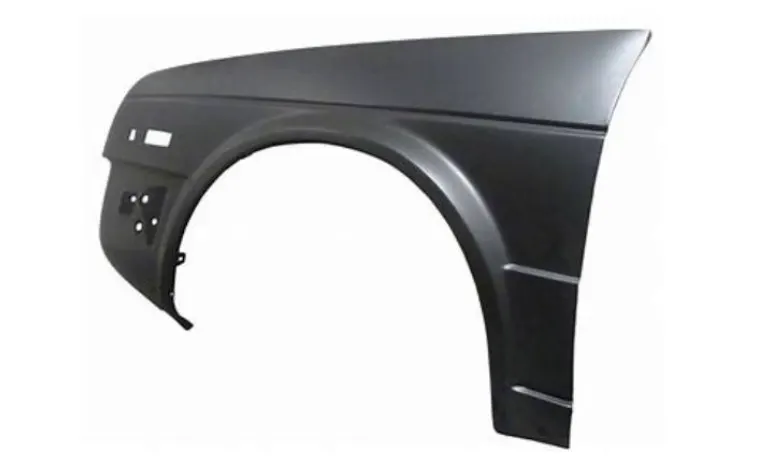
1) FULL BUMPER TYPE:
The Full Bumper Type Fender is the type of Fender used in olden days, where the Wheel arch was guided up-to Half the size of wheel. Full Bumper type is traditional type of fender where more material consumption is observed. This increases the overall weight and thus reduces performance. The maintenance also relatively more due to more surface.

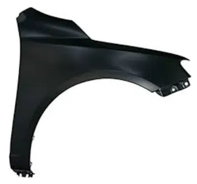
2) HALF BUMPER TYPE:
The Half Bumper type Fender is the upgraded version of the Full Bumper Type Fender. This is modern design where less material consumption is observed. So productivity increses by reducing size of blank and thus providing more performance. The maintenance also relatively low compared to full bumper type. The metal reduction in terms of overall weight of the car, increases the fuel efficiency of the car. it plays a important role in waste management.
FENDER DESIGN
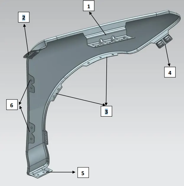
The Fender design is developed based on the type of Flanges that are created on the Fender, for mounting in Car.
There are 6 types of mounting regions on the fender, as follows: -
1) Drip Area Mounting.
2) A- Pillar Mounting.
3) Baffle Mounting.
4) Bumper Mounting.
5) Sill Mounting.
6) Door-Side Mounting.
1) Drip Area Mounting.
The Design Methodology Followed for The Development of Drip Area is based on the Design Inputs taken from the drawing shown below,
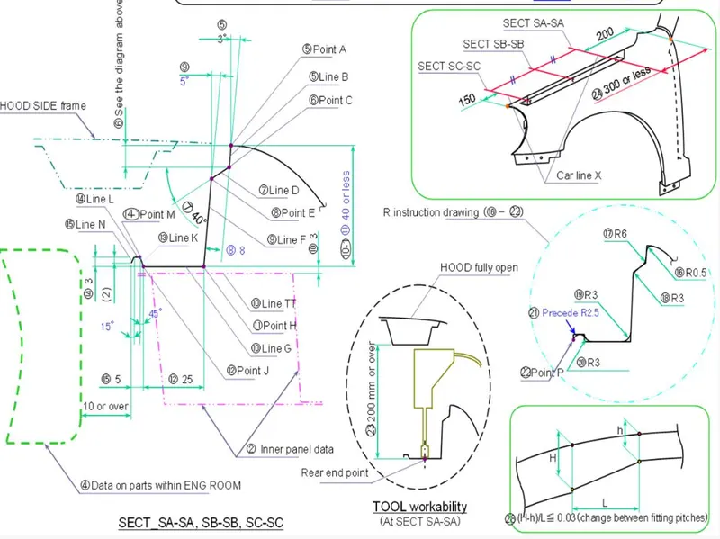
In the Above Drawing, the design considerations take are shown below,
• The Flanges for Drip Area starts from a distance of 200 to 300 mm from Cowl top/A-pillar Region.
• The Flanges for Drip Area Ends at a distance of 150mm behind the Headlamp Region.
• The Mountings on the Flanges are provided based on the placement of Fender in the car. The Necessary angles and extensions Provided for flanges makes sure that, the Fender provides minimum spring action after its mounting on the car. The more spring action of Fender leads to more vibration during the motion of the car.
• The minimum vertical distance for Tool Workability to mount the fendershould be 200mm or more than 200 mm, staring from the mountingpoint, when the hood is in fully open condition.
The Embosses are created on the Mounting region and The DARTS areplaced in intermediate positions of embosses to increase the Stiffness andstrength of the DRIP AREA.
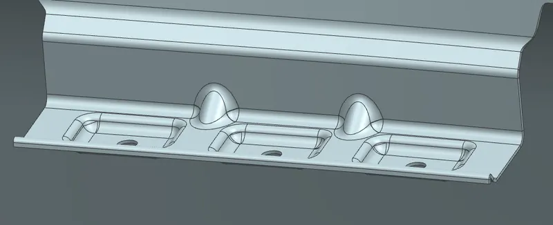
Image of DARTS on Drip area.
2) A-Pillar Mounting.
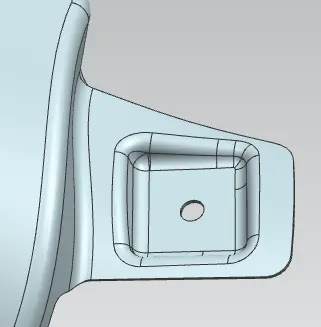
A pillar is on the cars either side of the front windshield, which is the reason the windshield in the place. It mounted on the A Pillar by means of the bolts and these are covered by outer side view mirrors.
3) Baffle Mouinting.
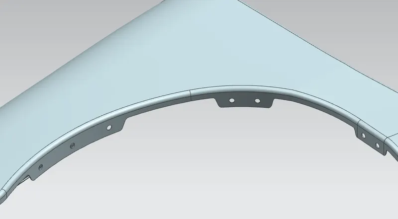
The Baffle Mounting is designed in accordance to the wheel arch of Fender. The Flanges for Baffle Mounting are provided in inner side, thus protecting the car engine compartment from damages incurred due to debris taken from the road, during the motion of car.
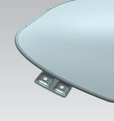
4) Bumper Mounting.
A Mounting area of the fender to bumper region. Bumpers are mostly made of plastic which covers the bottom front and back part of the car. It protect the car at the time of collisions.
5) Sill Mounting.
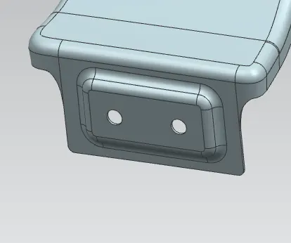
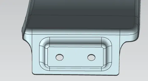
The mounting area at the panel directly to the bottom of door supporting floor. Which is bolted together and sill inner covers could cover the fasteners. This region comes at the bottom position of the fender, near to Door Side area. The Mounting Supports to the Floor of the Car chassis/body to make the Fender firmly attached and is aligned in line with the mounting holes provided near door side area. The Flanges for the Sill Mounting are internal and embosses are provided followed by creation of hole to align with the hole provided in car body for fasteners to accommodate.
6) Door side Mounting.
The Door Side Mounting is the Mounting provided near the Door area of the car body. The Flanges for the Door Side Mounting is provided internal to the fender. The Fastening of the Fender with respect to the internal flange provided is done along with the door area of the car body.
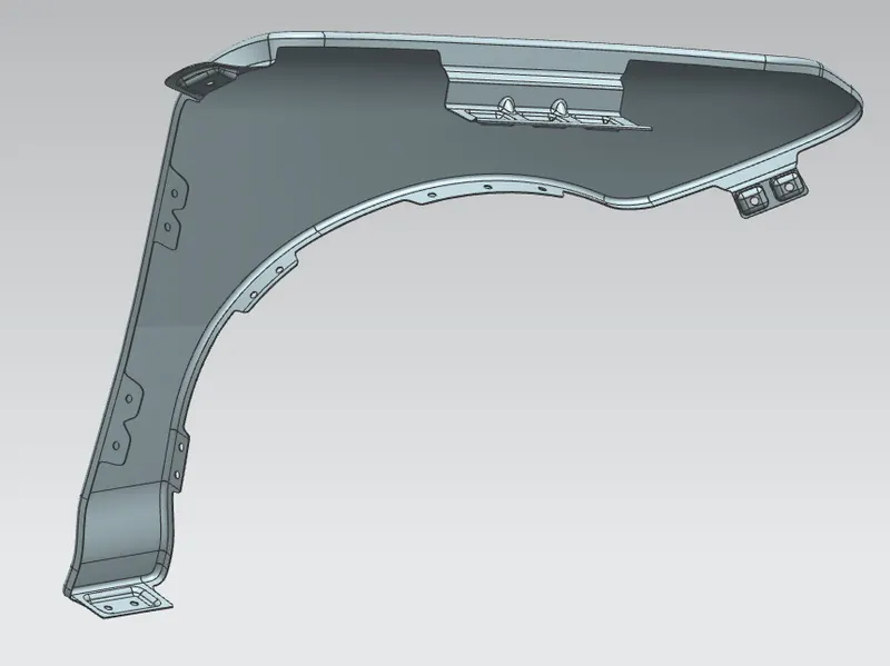
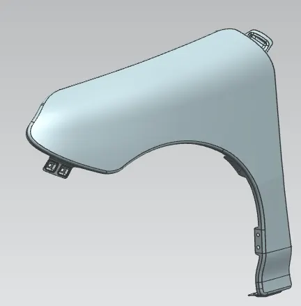
Final design.
MANUFACTURING PROCESS:-
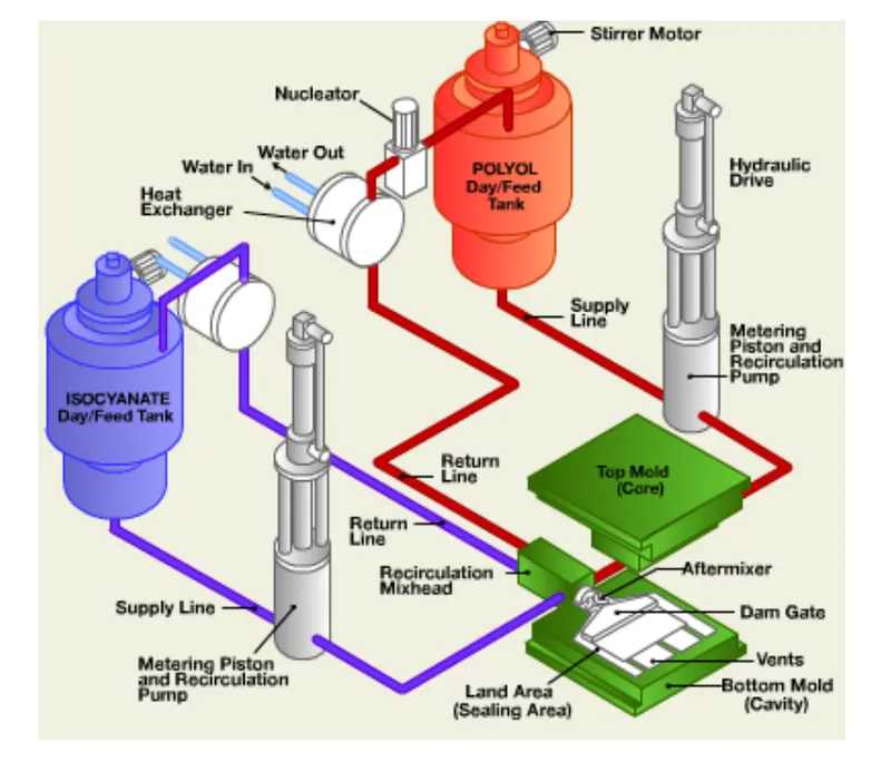
A car Fender bumper is made by a process called Reaction injection molding (RIM), which basically consists of making a special polyurethane compound and introducing it into a large fender. RIM is a process that conserves raw materials and reduces costs. It is similar to injection molding except thermosetting polymers are used, which requires a curing reaction to occur within the mold. Common items made via RIM include automotive bumpers, air spoilers, and fenders.
Reaction injection molding (RIM) is a relatively new way to produce structural plastic foams. In this process, highly reactive plastic liquids are mixed under high pressure and then injected into a mold to react, polymerize, and turn into foamed plastics.
RIM Process
The RIM process begins with polymer liquids (polyol and isocyanate) stored in storage tanks that are eventually dispensed by high-pressure industrial pumps. The polymers are recirculated from the storage tanks to a multi-stream mix-head and back to the storage tanks in a continuous loop.
The reaction injection molding (RIM) process utilizes low-viscosity liquid polymers. These polymers expand and thicken through a variety of chemical reactions. After the polymers have been injected into the heated mold they eventually harden. Through the RIM design process raw materials and molding techniques can be selected, and customized, to deliver the desired weight, strength, density and hardness characteristics that you are looking for. The result is polyurethane parts with much lighter weight, and more intricate designs than those created by ordinary injection molding.
RIM advantages.
RIM molding allows for many distinct advantages, some of which include:
- Large Parts - The properties of the liquid polyurethane components enable them to fill molds for very large parts.
- Encapsulation of Inserts - Inserts of many types can be placed into a mold prior to injection of the RIM material. The RIM material can also encapsulate many inserts during molding.
- Thick and Thin Walls - The RIM process offers you the flexibility to design parts with significant wall thickness variations.
- Class-A Surfaces - The surface finish of parts molded with the RIM process allows manufacturers to produce Class A painted parts.
- Low Cost Tooling Options - The low injection pressures of the RIM process allow for tooling to be manufactured quicker, and at lower cost, than tools used in traditional injection molding, or structural foam.