Fender Design
FENDER DESIGN
The “fender” typically refers to the front panel that covers the front wheels, and the “quarter panel” typically refers to the rear panel that covers the wheel that also includes the roof pillar. The “bumper” is the front and rear ends of a motor vehicle to absorb impact in a minor collision.
The fender car part is the body kit or body part installed on the left and right sides of the vehicle. Manufacturers usually attach fenders to the wheel arches. There are different reasons why they are a requirement in vehicles. One obvious reason is to improve the aesthetics of the vehicle.
Fenders also enhance the car’s aerodynamics. They also prevent mud, sand, rocks, liquid, and all sorts of debris from being thrown in the air while you’re driving your car.
A fender is the part of a car that covers the wheel and extends up to the body of the car. The three main sections of a fender are:
–The inner fender: This is the section closest to the engine and other mechanical parts of the car. It is typically made of metal or plastic and helps to protect these parts from debris.
–The outer fender: This is the section that is visible on the outside of the car. It is typically made of metal, plastic, or fiberglass, and it helps to protect the body of the car from debris.
–The trim: This is the section that goes around the edge of the fender. It is typically made of plastic or metal and helps to give the car a finished look.
Types of Fenders:
- Full Bumper type
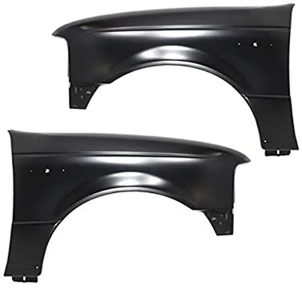
- Half Bumper type
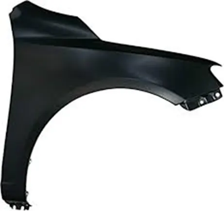
- Mounting Points of Fender:
- A-Pillar
- Bumper
- Sill
- Drip Area
- Splash Cover / Wheel Well
According to fender and wheel arch there are three types of regulation in world wide which are
- Japan Requirements for fender wheel arch:
- US Standards regulation for fender wheel arch:
- European regulation:
Previously we analysis the fender and wheel arch with EUROPEAN REGULATION.
As per the European regulation the design of fender wheel was failed because the distance between the points is less than 10.
So, we designing a new fender.
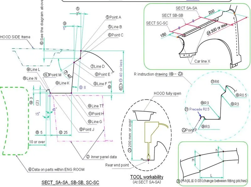
According to fender and wheel arch there are three types of regulation in world wide which are
- Japan Requirements for fender wheel arch:
- US Standards regulation for fender wheel arch:
- European regulation:
Previously we analysis the fender and wheel arch with EUROPEAN REGULATION.
As per the European regulation the design of fender wheel was failed because the distance between the points is less than 10.
So, we designing a new fender.
PROCESURE:
The skin of the fender is given and we have to design the Pillar, Bumper, Sill, Drip Area, Splash Cover / Wheel Well.
The inner side of the skin where the design of drip, sill, bumper, pillar areas must be offset to increase the surface by( offset in face) and we must trim the surfaces accordingly with calculated length.
Drip Area:
The drip area calculation from the point on bumper area creating a datum plain of length 150mm and from point on pillar area creating a datum plain of length 200mm right.
The area between to datum plains is the area to design drip , so for marking taking the curve intersection and marking two datum plains on surface.
With command (curve on surface) marking the intersected lines for trimming.
Trim all the extra portions beyond the marking with the (trim sheet) command.
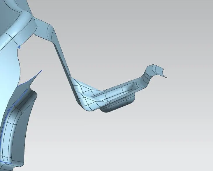
The trim surface of drip area was increased by command (law extinction).
To design the drip area we must use the command law extinction by 6 times with different lengths and different angels.
- 1LE- 10mm -40deg OR 275deg
- 2LE- 35mm 50deg to 1LE in reverses direction
- 3LE- 30mm 90deg to 2LE
- 4LE- 5mm -45 deg to 3LE
- 5LE- 3mm 90 deg to 4LE
- 6LE- 5mm 315deg to 5LE.
4LE, 5LE, 6LE are created a vibration control structure to reduce the vibration.
SEW all the surfaces.
Creating DARTs between LE2 and 3LE to get the strength.
All the edges are blended with edge blend command according to the radius given.
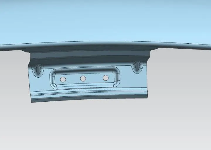
Creating a datum plane on 3LE and creating a sketch to make the embosses and project the sketch.
Taking a new sketch for holes and assigning the same datum plain and project the sketch.
- By using the command embosses the projected curves are embossed.
- By using the command trim sheet, the projected curves for holes are trimmed.
Sill, Bumper, Pillar:
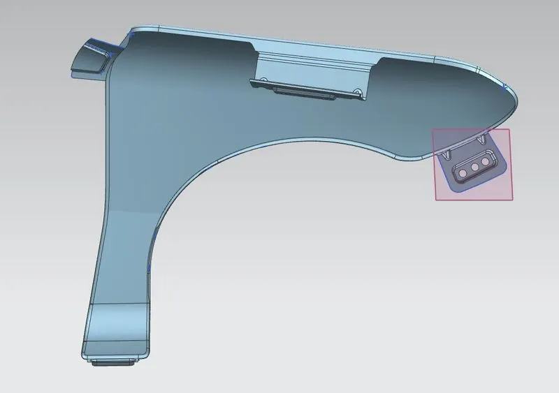
With the command curve on surface marking all areas of sill bumper and pillar the area to which they are satiated.
Trim all the extra portions beyond the marking with the (trim sheet) command.
Law extension for pillar area and bumper area with 30mm and 90 deg.
Sheet extends for sill area with 15mm.
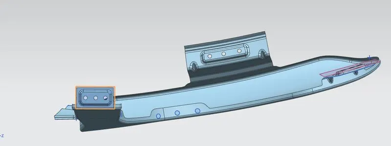
Creating a datum plane on sill area, Law extensions of pillar and bumper and creating a sketch to make the embosses and project the sketch.
Taking a new sketch for holes and assigning the same datum plain and project the sketch.
- By using the command embosses the projected curves are embossed.
- By using the command trim sheet, the projected curves for holes are trimmed.
Conclusion:
Designed a new fender according to European regulations.
Now all the points of SA,SB,SC,SD,SE will have the distance of ≤ 10.