FEA Using SolidWorks Project 4 : Frequency Analysis of a rotating shaft
AIM :
Frequency Analysis of a rotating shaft using finite elemet analysis method.
Objective :
The aim of the project is to conduct a frequency analysis on a shaft with a disc mounted on it and determine the corresponding resonant frequencies and the mode shapes.
Introduction :
Natural Frequency: All physical structures have natural frequencies. These are the frequencies at which the structure will tend to vibrate when subjected to certain external forces. These frequencies are dependent on the way mass and stiffness are distributed within the structure.
Resonance: Resonance is a phenomenon in which a dynamic force drives a structure to vibrate at its natural frequency. When a structure is in resonance, a small force can produce a large vibration response.
When a dynamic force is applied to a physical object, it will vibrate. When a force is applied at the object’s natural frequency, it goes into resonance, and a higher amplitude vibration response is created.
All physical objects have multiple natural frequencies and can resonate under the right conditions. Sometimes the natural frequencies are excited by external forces acting on the object, which creates vibration. These vibrations may be so small that they cannot be seen by the human eye. Sometimes, they are quite large and easily observable.
The identification of these natural frequencies in a rotating shaft is very important in order to avoid resonance conditions in the operation which may lead to excessive vibration or even failure. This is exactly what has been done in this project. The natural frequencies of the rotating shaft are found and are documented so that during the future use of the shaft, these frequencies could be avoided for safe operation.
Procedure :
The entire process of performing a Solidworks simulation can be divided into four parts.
1. Part design
Includes making the cad model of the system that is to be analyzed and assigning materials to the components.
2. Setting up of boundary conditions
Includes setting up the fixed supports, reactions and external loads.
3. Meshing
The type, size and various other mesh parameters are setup.
4. Solver Analysis
The solver is run giving out the results. In the case of frequency analysis, the results include different modes and resonant frequencies.
SIMULATION PROCEDURE :
1. Part design
The model of the shaft with a mounted disc is designed with the dimensions as indicated below.
The full length of the shaft is 300mm of which, 10mm on each side is stepped and is used for bearing support. The disc is mounted exactly at the center of the shaft with a thickness of 10mm.
The diameter of shaft is 20mm and the diameter of the disc is 80mm which are indicated in the figure below.
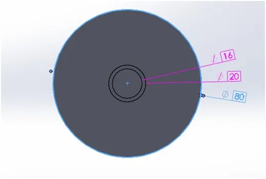
The isometric view of the part is shown below.
Material properties:
The material of the shaft and disc is chosen to be alloy steel, the properties of which are given in the table below.
Name: Alloy Steel
Model type: Linear Elastic Isotropic
Default failure criterion: Max von Mises Stress
Yield strength: 6.20422e+08 `N/m^2`
Tensile strength: 7.23826e+08 `N/m^2`
Mass density: 7700 `{kg}/m^3`
Elastic modulus: 2.1e+11 `N/m^2`
Poisson's ratio: 0.28
Thermal expansion coekcient: 1.3e-05 /Kelvin
2. Boundary Conditions
Once the model has been developed and materials have been assigned, the next step is to establish bearing fixtures on the shaft. Here, the stepped part of the shaft on either ends is used as the bearing support area and is selected under fixed geometry.
3.Meshing
Meshing is done to the part and the meshed part is shown below.
The parameters of meshing are given in the table below.
Mesh type Solid Mesh
Mesher Used: Standard mesh
Automatic Transition: Off
Include Mesh Auto Loops: Off
Jacobian points 4 Points
Element Size 5.183 mm
Tolerance 0.25915 mm
Mesh Quality Plot High
Total Nodes 11320
Total Elements 6619
Maximum Aspect Ratio 4.0398
% of elements with Aspect Ratio < 3 98.7
% of elements with Aspect Ratio > 10 0
% of distorted elements(Jacobian) 0
4. Analysis
Analysis type Frequency
Mesh type Solid Mesh
Number of frequencies 5
Solver type FFEPlus
Soft Spring: Off
Incompatible bonding options Automatic
Thermal option Include temperature loads
Zero strain temperature 298 Kelvin
Include fluid pressure effects from SOLIDWORKS Flow Simulation Off
RESULTS:
Mode 1
|
Name |
Type |
Min |
Max |
|
Amplitude1 |
AMPRES: Resultant Amplitude Plot for Mode Shape: 1(Value = 743.255 Hz) |
0.000e+00 Node: 244 |
1.257e+00 Node: 371 |
Mode 2
|
Name |
Type |
Min |
Max |
|
Amplitude2 |
AMPRES: Resultant Amplitude Plot for Mode Shape: 2(Value = 743.954 Hz) |
0.000e+00 Node: 244 |
1.257e+00 Node: 341 |
Mode 3
|
Name |
Type |
Min |
Max |
|
Amplitude3 |
AMPRES: Resultant Amplitude Plot for Mode Shape: 3(Value = 1205.61 Hz) |
0.000e+00 Node: 244 |
2.233e+00 Node: 283 |
Mode 4
|
Name |
Type |
Min |
Max |
|
Amplitude4 |
AMPRES: Resultant Amplitude Plot for Mode Shape: 4(Value = 2461.39 Hz) |
0.000e+00 Node: 244 |
2.095e+00 Node: 9191 |
Mode 5
|
Name |
Type |
Min |
Max |
|
Amplitude5 |
AMPRES: Resultant Amplitude Plot for Mode Shape: 5(Value = 2463.26 Hz) |
0.000e+00 Node: 244 |
2.097e+00 Node: 9516 |
Mode List
|
Frequency Number |
Rad/sec |
Hertz |
Seconds |
|
1 |
4670 |
743.25 |
0.0013454 |
|
2 |
4674.4 |
743.95 |
0.0013442 |
|
3 |
7575.1 |
1205.6 |
0.00082945 |
|
4 |
15465 |
2461.4 |
0.00040627 |
|
5 |
15477 |
2463.3 |
0.00040597 |
CONCLUSION
It is understood that the shaft should not be operated at the indicated resonant frequencies i.e. 743.25 Hz, 743.95Hz, 1205.6Hz, 2461.4Hz, 2463.3Hz since doing so would result in resonance phenomenon and may lead to failure of the shaft.