External aerodynamics over Mercedes Benz actros truck.
AIM:
To perform a external flow over Mercedes Benz Actros truck where two cases are to be simulated one with container and other without container.
PROCEDURE:
Flow over a truck is highly necessary to understand the drag and lift associated with the vehicle. The case with container has a tilted position which occurs when vehicle loses its traction and let us assume such condition and perform the analysis and briefly discuss the results.
The surface file is being imported into star ccm+ where it comes with various parts which has to be combined as a single unit in order to create a single region for the surface.
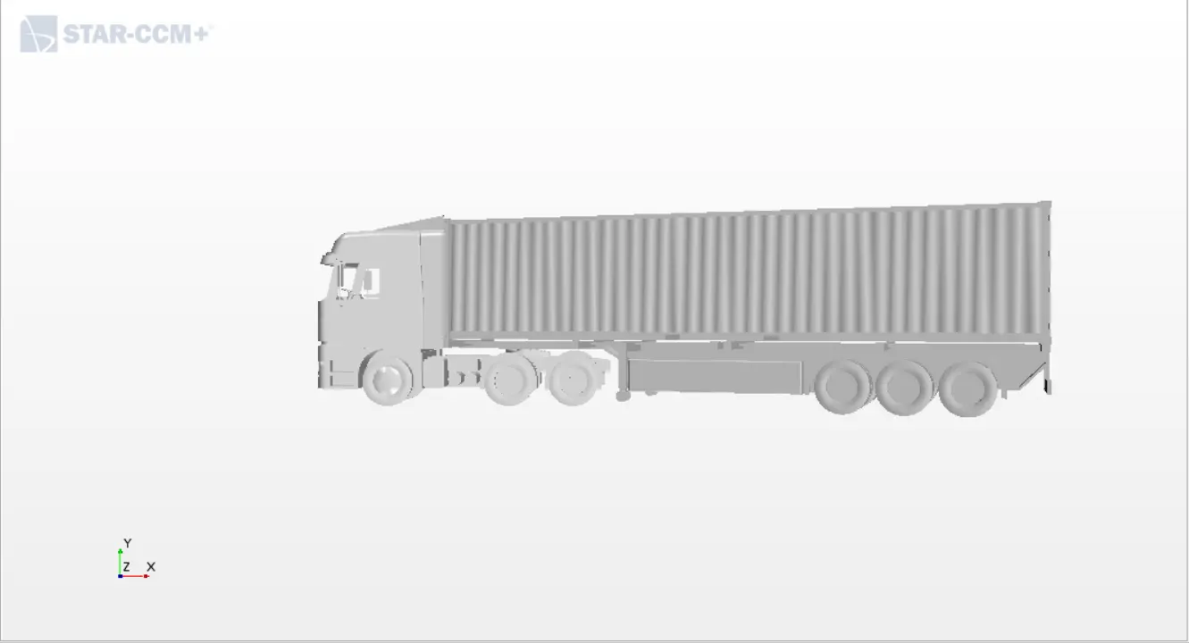
The body is oriented properly i.e, it is being rotated to alingn the flow in X direction which makes the work way better.
Now the surface errors have to be verified. Thw windows and windshield have to be closed in order to have a proper water tight model.
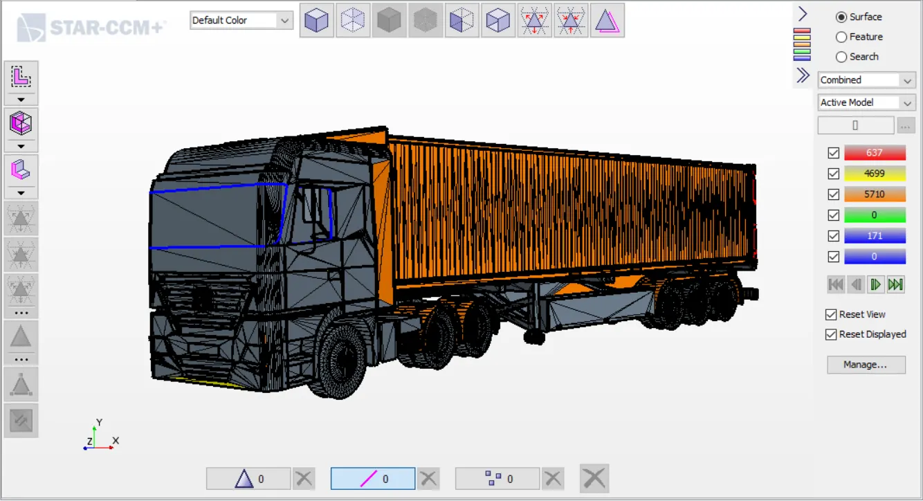
We can see that we are having many peirced faces and manifold edges which cannot be manually rectified so surface wrap is essential in this case.
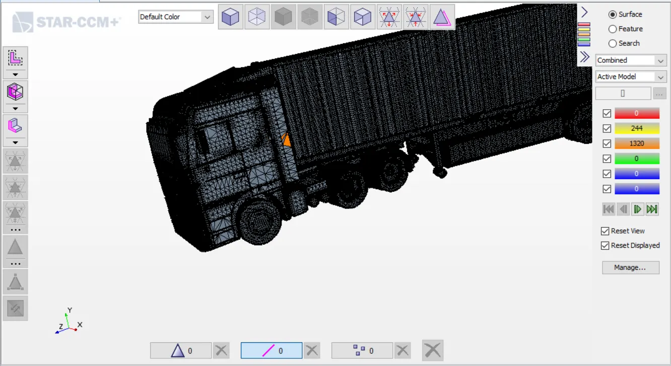
base size - 0.01m
Volume intrest - External
next step is to create the wind tunnel setup.
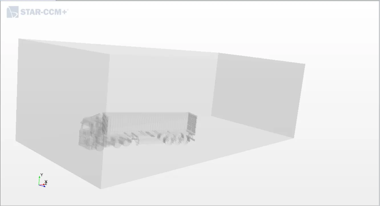
Next step is to use boolean command and subtract the wrap from the cuboid which will create an imprint of the truck on the volume of the cuboid.
Now we can move on to meshing. Before mesh we have to assign the parts by proper naming to the regions.
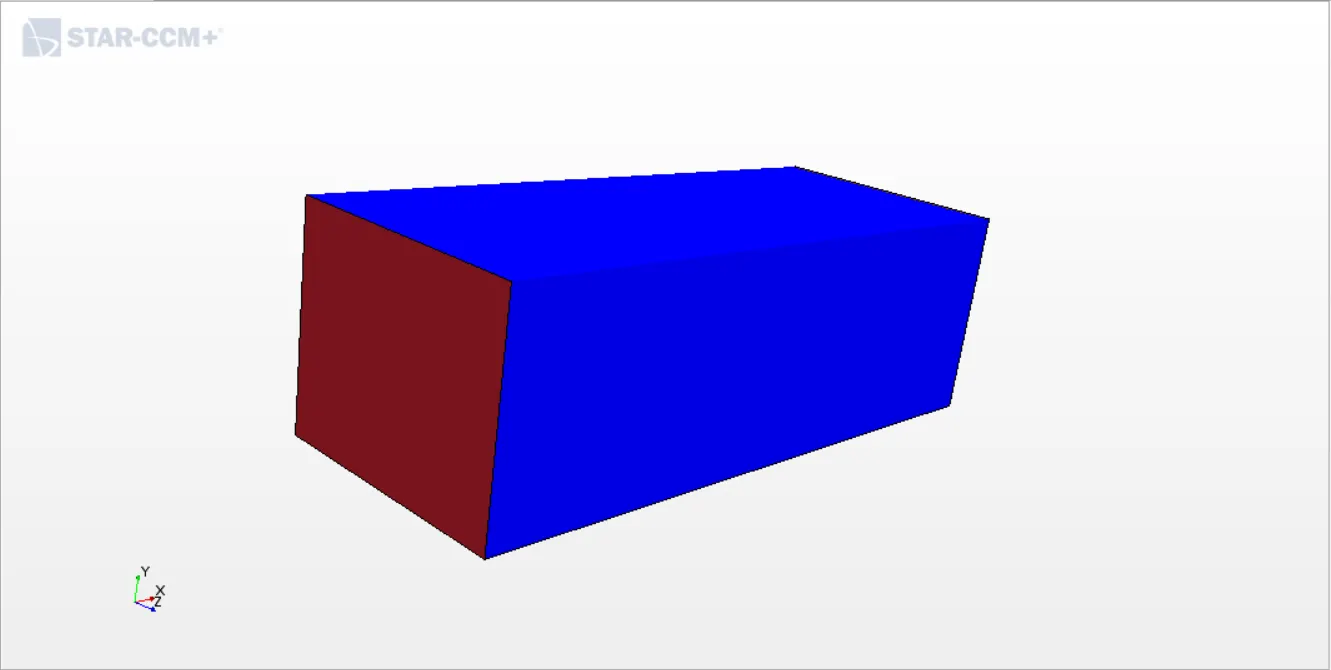
The inlet is given as velocity inlet, outlet as pressur outlet walls as symmetry walls and truck and road as walls.
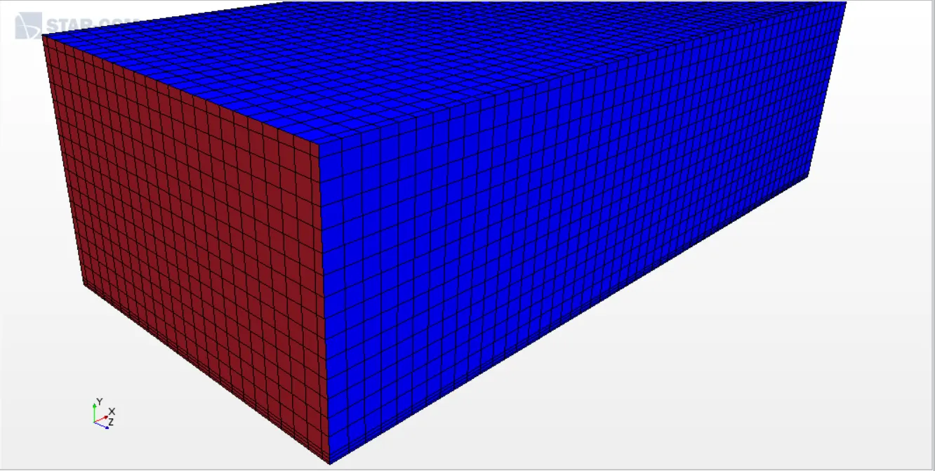
Now we can move on with meshing. We have provide a custom mesh for truck.
Base mesh - 0.4 m
Target surface size - 100% base mesh
Minimum surface size - 10% of base mesh
Custom control : wraped truck
Target surface size - 20% base mesh
Minimum surface size - 10% base mesh
wake refinement - growth rate - medium with 0deg spread angle.
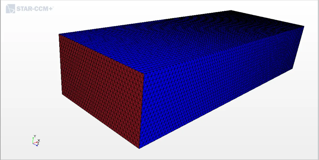
Now we can move onto volume mesh
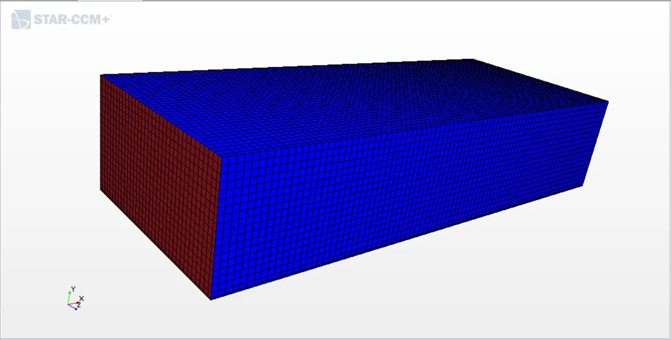
Next step is to specify physics continua
Steady> Turbulent> staggered> Kepsilon
Initial conditions - velocity 20m/s
The regions have to be given proper boundary conditions
Inlet - 33.33m/s
The reports play a major role in identifing the values from simulation.
Frontal area:
View up - 1,0,0
Normal - 0,1,0
Part - truck
Force coefficient Drag
Flow direction - 1,0,0
Reference density - get the value from continua physics
reference velocity - 33.33m/s
Referance area - frontal area
Part - Truck
Force coefficient Lift
Same as drag just the direction will be 0,1,0
The simulation has to be run and the results are as follows
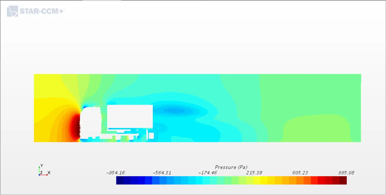
Pressure contour:
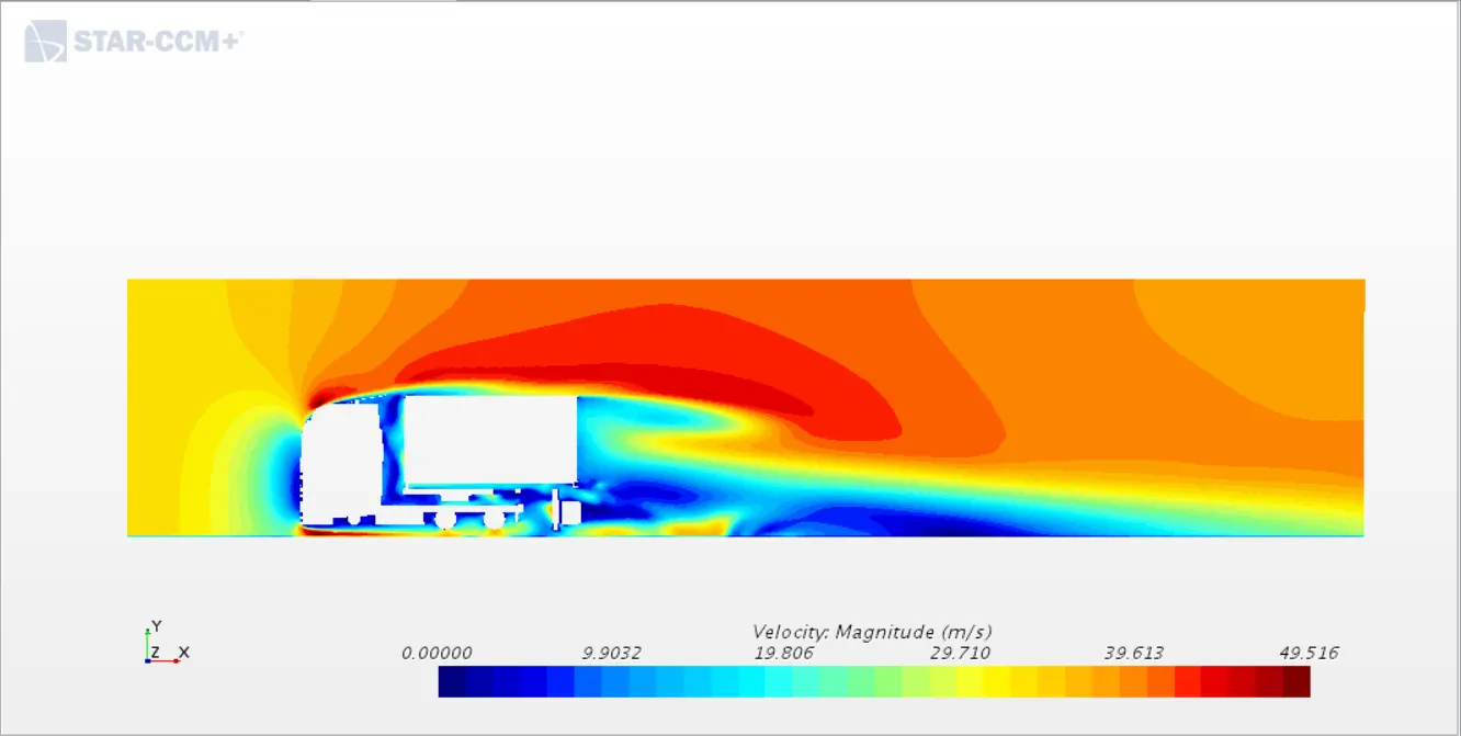
Velocity Contour
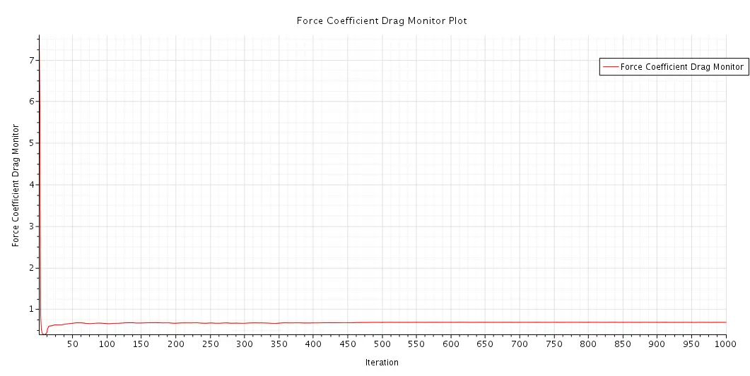
Drag coefficient:
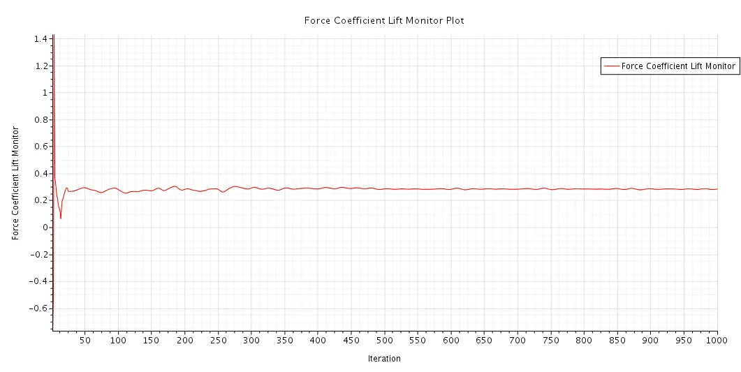
Lift coefficient:
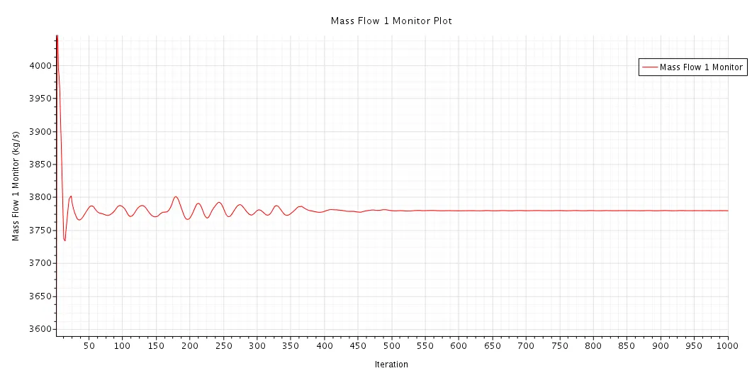
Mass flow
The post processing videos
The planar continuos sweep and flow at different section: https://youtu.be/_i8RVYDwv1U
Flwo along a plane section : https://youtu.be/w6URQJomswo
Stream lines generated from seed point: https://youtu.be/XLXFohGWbzg
For Case without trailer and container
The surface file is being imported into star ccm+ where it comes with various parts which has to be combined as a single unit in order to create a single region for the surface.
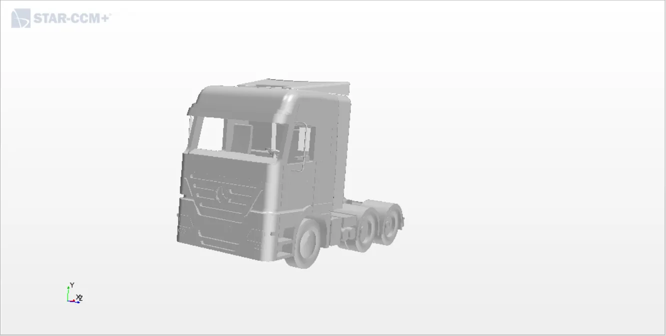
The body is oriented properly i.e, it is being rotated to alingn the flow in X direction which makes the work way better.
Now the surface errors have to be verified. Thw windows and windshield have to be closed in order to have a proper water tight model.
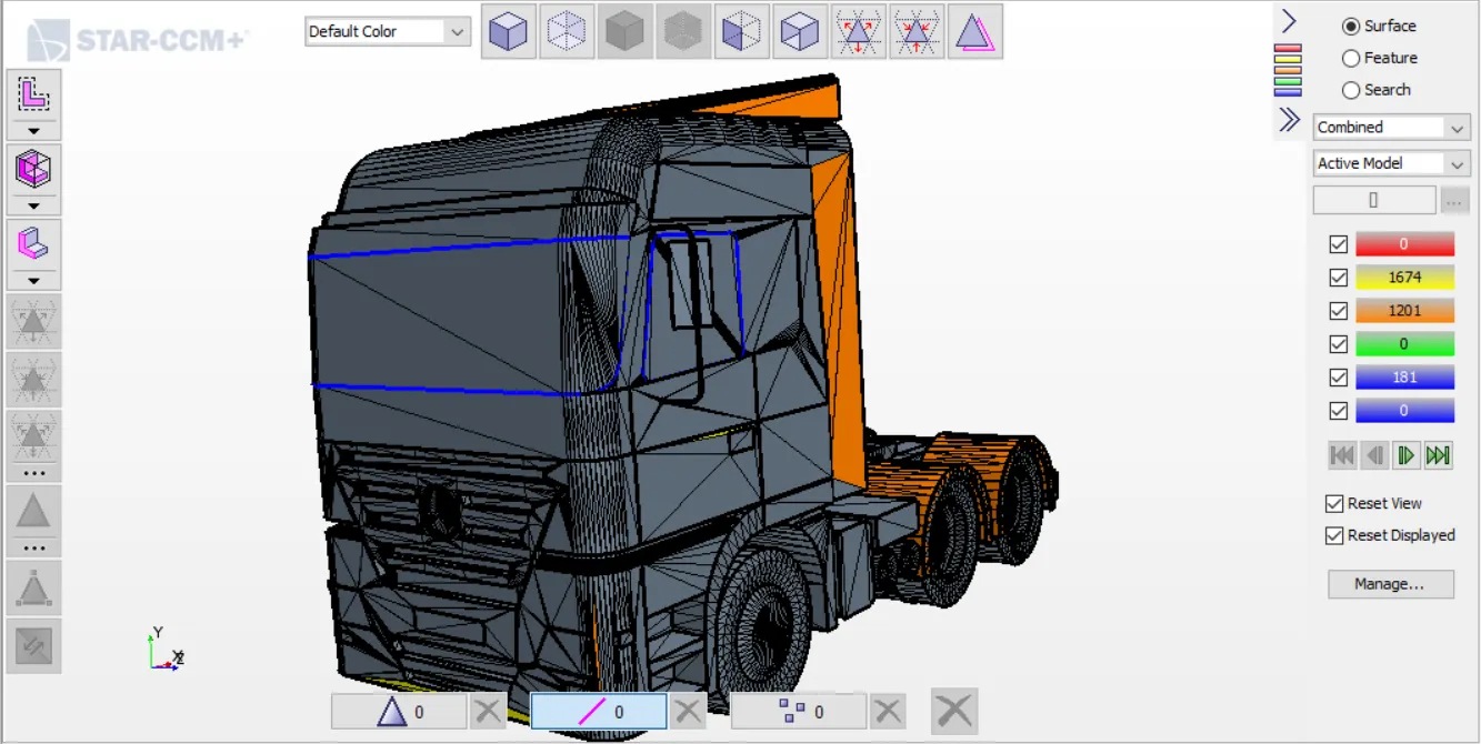
We can see that we are having many peirced faces and manifold edges which cannot be manually rectified so surface wrap is essential in this case.
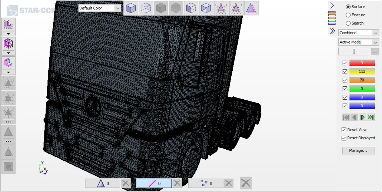
base size - 0.01m
Volume intrest - External
next step is to create the wind tunnel setup.
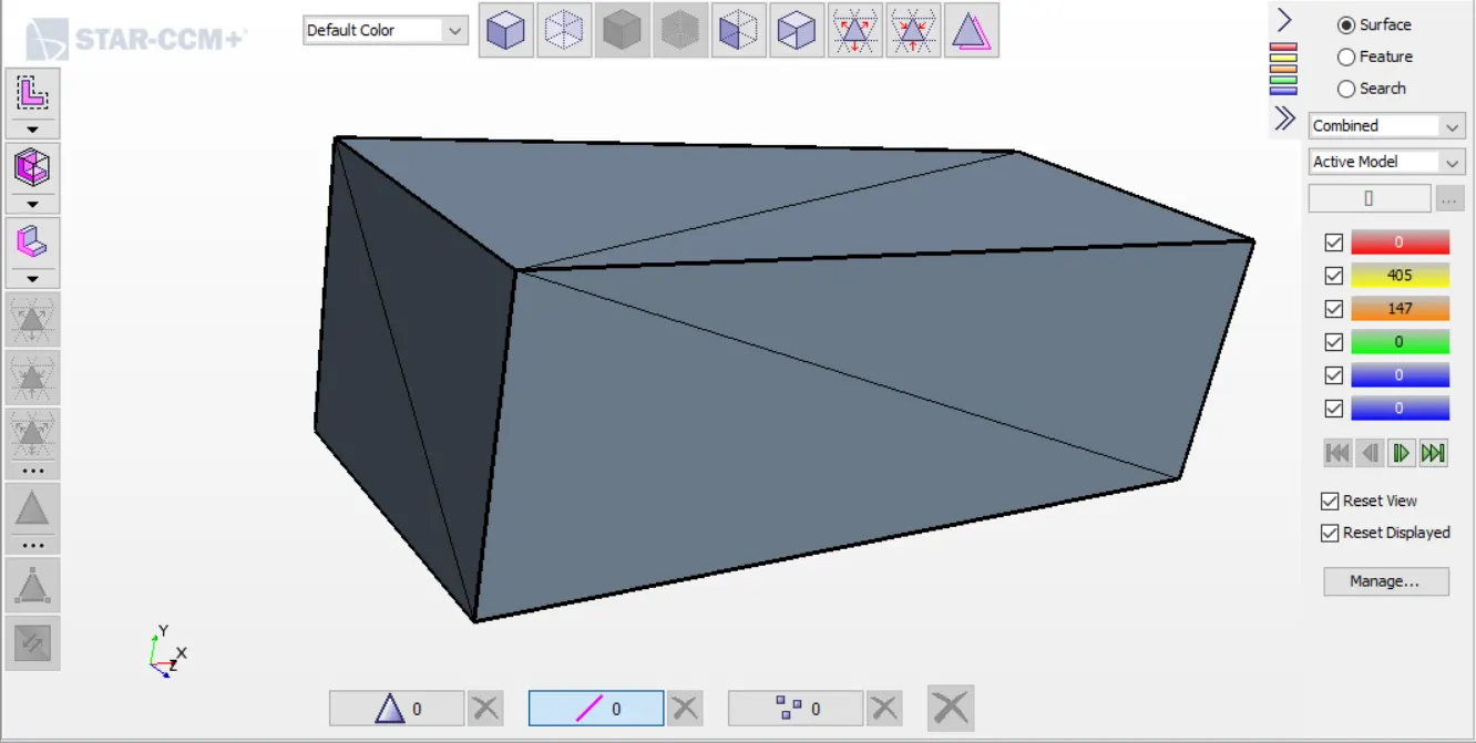
Next step is to use boolean command and subtract the wrap from the cuboid which will create an imprint of the truck on the volume of the cuboid.
Now we can move on to meshing. Before mesh we have to assign the parts by proper naming to the regions.
The inlet is given as velocity inlet, outlet as pressur outlet walls as symmetry walls and truck and road as walls.
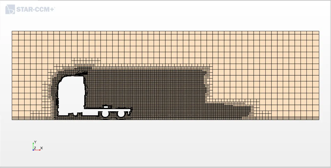
Now we can move on with meshing. We have provide a custom mesh for truck.
Base mesh - 0.4 m
Target surface size - 100% base mesh
Minimum surface size - 10% of base mesh
Custom control : wraped truck
Target surface size - 20% base mesh
Minimum surface size - 10% base mesh
wake refinement - growth rate - medium with 0deg spread angle.
Next step is to specify physics continua
Steady> Turbulent> staggered> Kepsilon
Initial conditions - velocity 20m/s
The regions have to be given proper boundary conditions
Inlet - 33.33m/s
The reports play a major role in identifing the values from simulation.
Frontal area:
View up - 1,0,0
Normal - 0,1,0
Part - truck
Force coefficient Drag
Flow direction - 1,0,0
Reference density - get the value from continua physics
reference velocity - 33.33m/s
Referance area - frontal area
Part - Truck
Force coefficient Lift
Same as drag just the direction will be 0,1,0
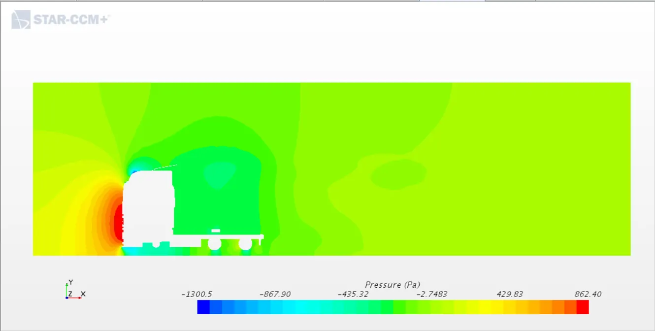
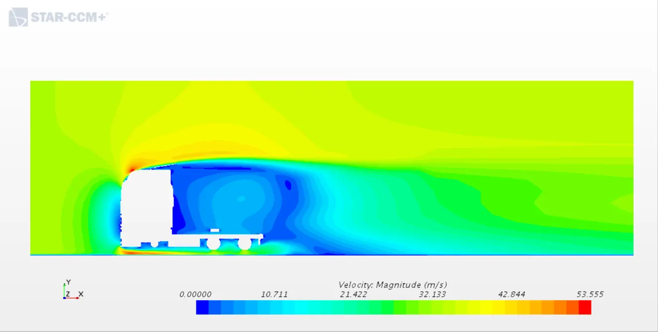
The simulation has to be run and the results are as follows
Pressure contour:
Velocity_contour:
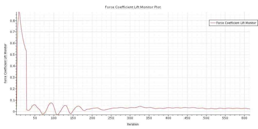
Lift coefficient:
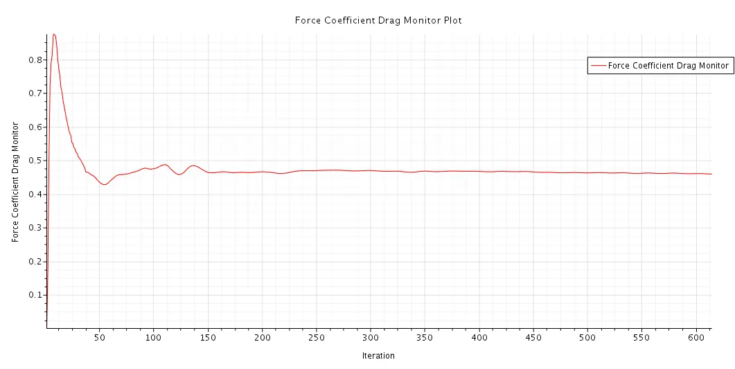
Drag coefficient:
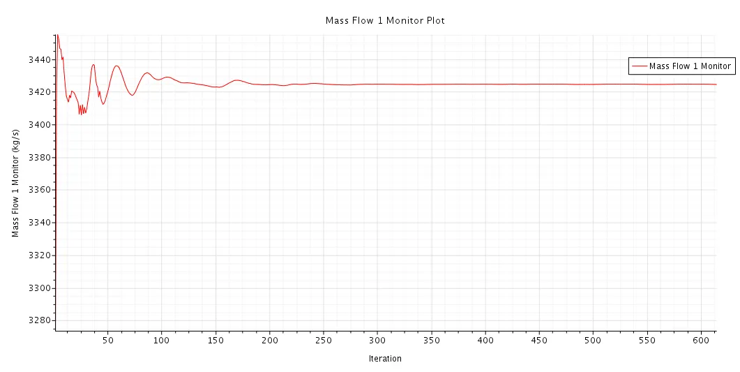
Mass flow outlet:
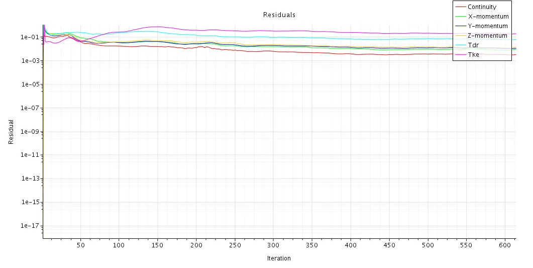
Residual plot
The planar continuos sweep and flow at different section: https://youtu.be/qKS0TKEOajU
Flwo along a plane section : https://youtu.be/o0sV7RD0eyg
Stream lines generated from seed point: https://youtu.be/X5I9GYlh4aQ
CONCLUSION:
The drag and lift for two different case of mercedes benz actros truck has been fund where the one with container has;
Drag - 0.680037
Lift - 0.2844
Similarly for the one without container;
Drag - 0.4594
Lift - 0.02399
Hence we can conclude that the truck with container has more drag due to more surface area and also the circualtion of air is too high in the case of truck without container.
The model: https://drive.google.com/file/d/1xZzat0d9M0dD8z7Xf5_tF22SnD6YlBSz/view?usp=sharing