Exhaust Port Challenge
Abstract:Conjugate Heat Transfer Analysis over Exhaust port and calculation of wall/surface heat transfer coefficient on the internal solid surface .
The term CHT is used to decsribe processes where heat transfer or variation of temperature takes place between solids and fluids.
Heat transfer in solids and heat transfer in fluids are combined in the majority of applications. This is because fluids flow around solids or between solid walls, and because solids are usually immersed in a fluid.
Importance in Practical application:
In automobile ,Marine industries and many more it is utmost important.For maintaining the fluid at certain temperature in the system-design of Heat exchanger,fluid used for heating or cooling ,its heat transfer coefficient and its flow control is most prior.
Sometime inability to maintain certain temperature in the system can cause its failure ,it can be an Engine,Heat exchanger etc.
Solving & Modelling approach:
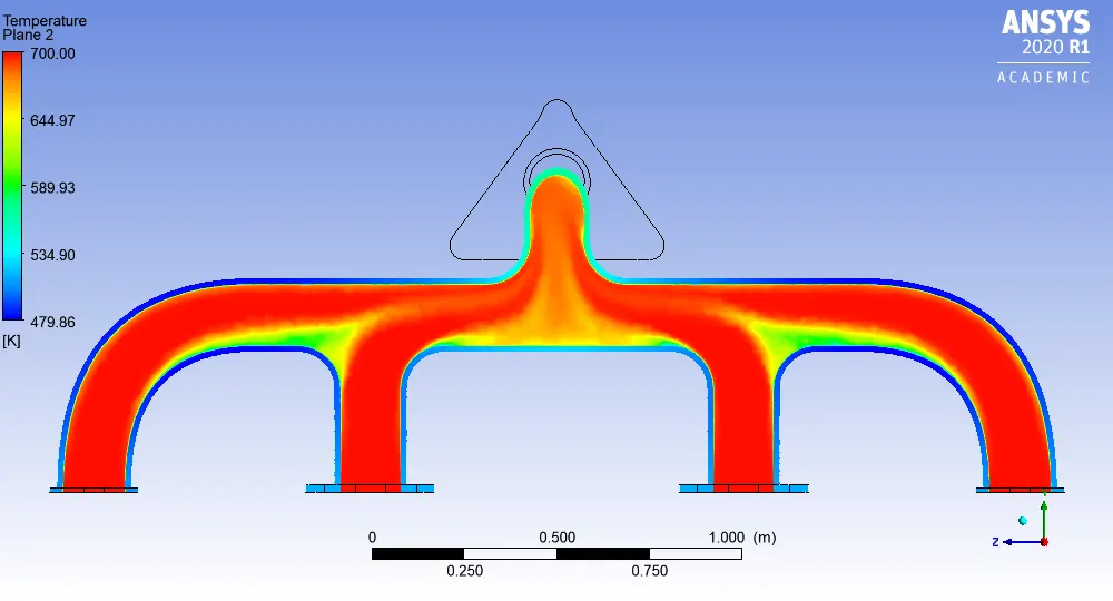
We will run case setup for two cases
1.Coarse Mesh
2.Refined Mesh(with addition of inflation layer)
In Spaceclaim prepare geometry and then meshing it according to required case setup.
Turbulence model used is `komegasst`
Setting up case and boundary condition,material for model.
Then Post process results to evaluate Wall Heat transfer Coefficient,Velocity and Temperatures distribution.
Pre-processing and solver setting:
1.Coarse Mesh Setup:
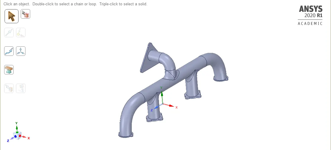
#Geometry:
a.Solid volume
b.Fluid Volume
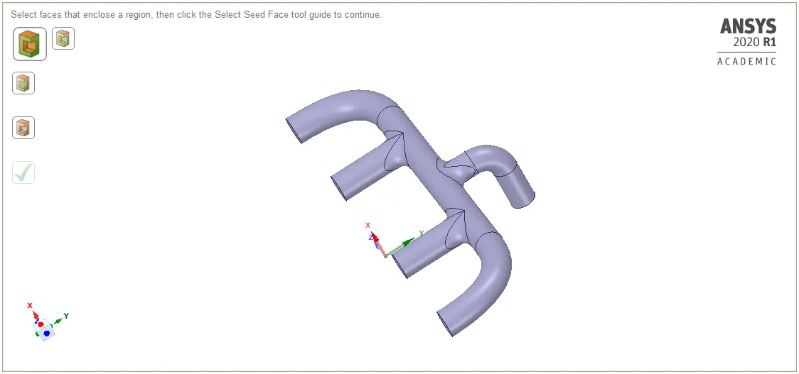
Geometry was imported in Spaceclaim
Fluid volume was extracted by Volume extract tool.
For transfer of properties between two volumes ,share topology feature was enabled.
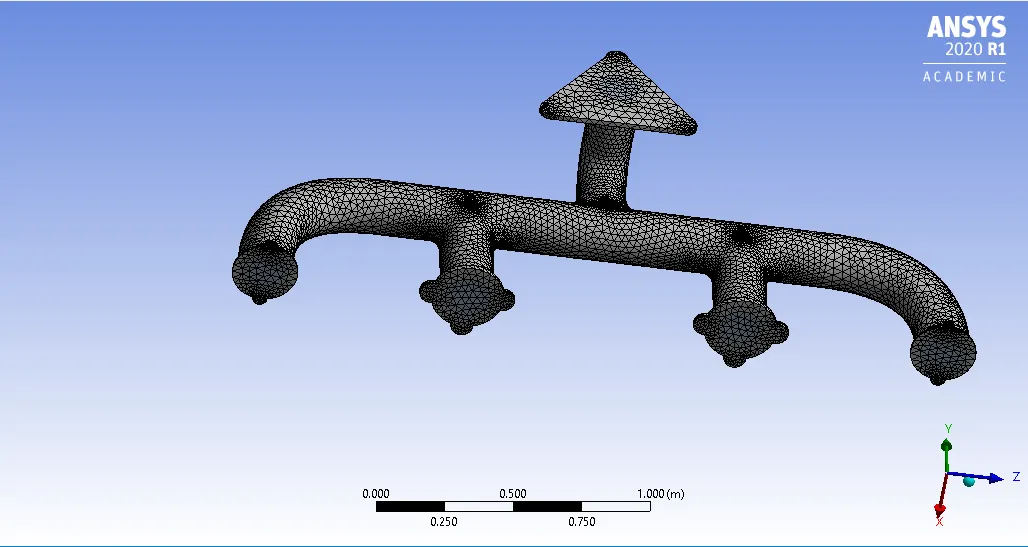
Meshing:
Global Element size-0.1m
Setup:
Pressure based,steady state solver is used
Turbulence Model-`komegasst`
Material:
For Fluid-Air
For Solid- Aluminium
Setting Temperature contour and its Animation for Solid volume.
Hybrid Initialization of solution,then running for 200 iterations.
Results:
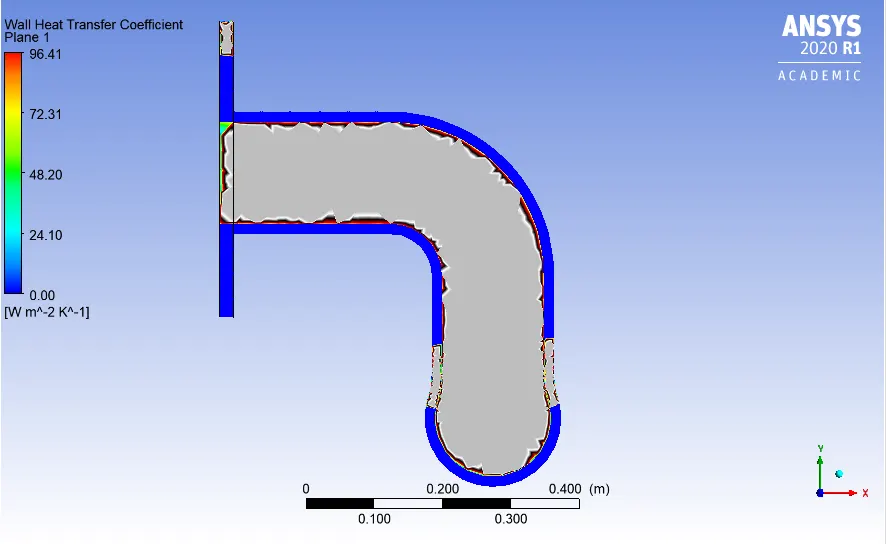
1.Wall Heat transfer coefficient plot near Outlet:
2.Velocity Plot near outlet:
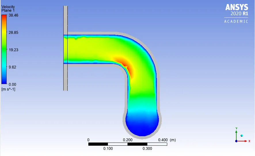
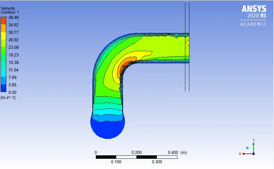
3.Velocity contour plot near outlet
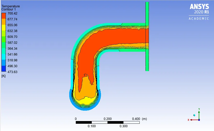
4.Temperature contour plot near outlet
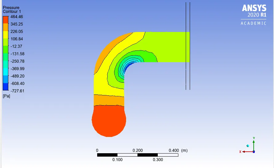
5.Pressure contour plot near outlet
6.Velocity streamline plot from inlet to Outlet
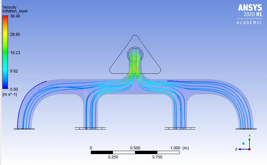
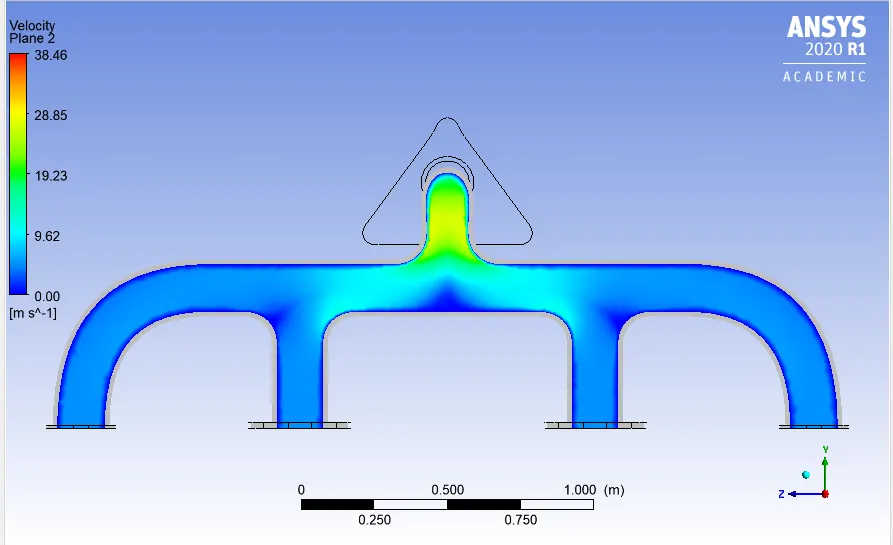
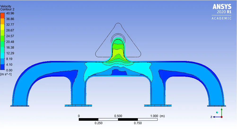
7.Velocity Plot over entire exhaust port(@ Cut plane)
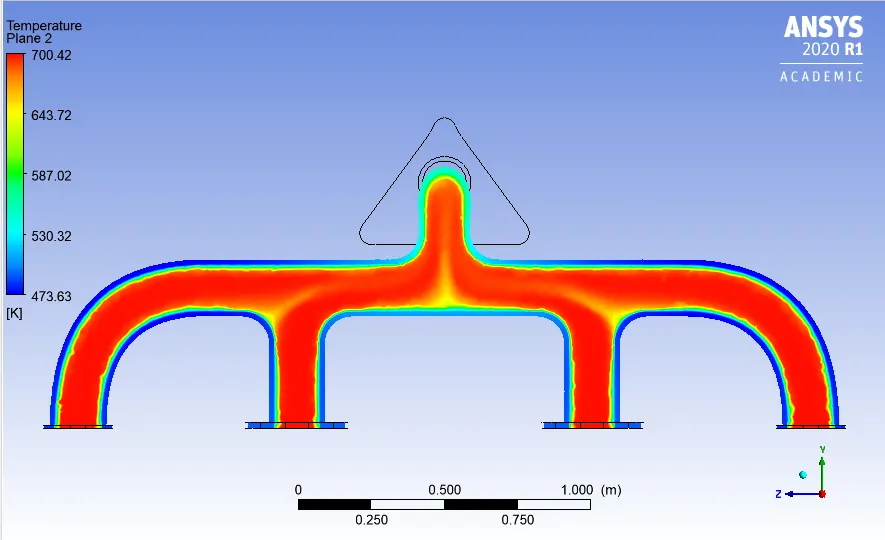
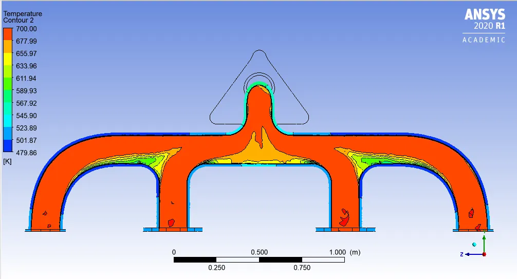
8.Temperature Plot over entire exhaust port(@ Cut plane)
2.Refined Mesh case
a).Geometry:No change in geometry preparations.
b).Meshing:
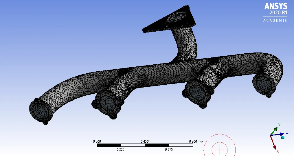
Global Element size-0.15 m
Inflation layer--
First Layer thickness-0.00005m
No of layers-5
Body sizing in Outer wall convection region-0.009m
Total number of cells-445478
c).Setup:
Same as described in above case.
Hybrid Initiatization and running simulation for 100 iteration.
d).Results:
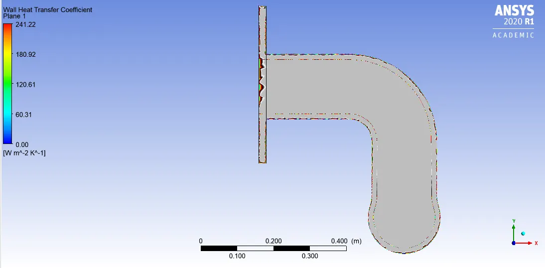
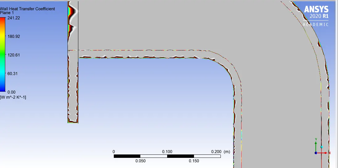
1..Wall Heat transfer coefficient plot near Outlet:
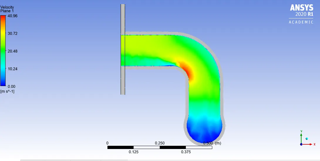
2.Velocity Plot near outlet:
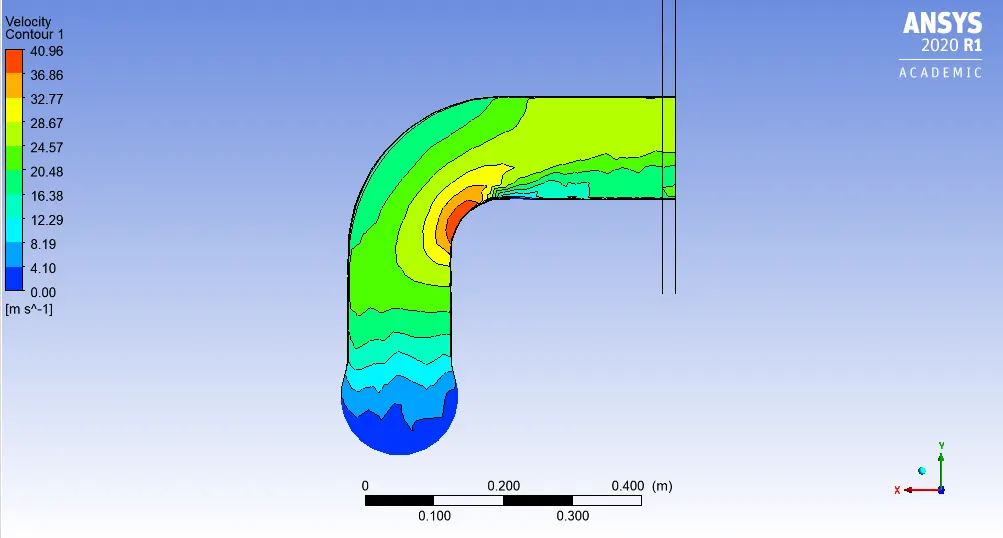
3.Velocity contour plot near outlet
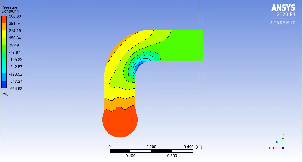
4.Pressure contour plot near outlet
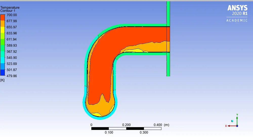
5.Temperature contour plot near outlet
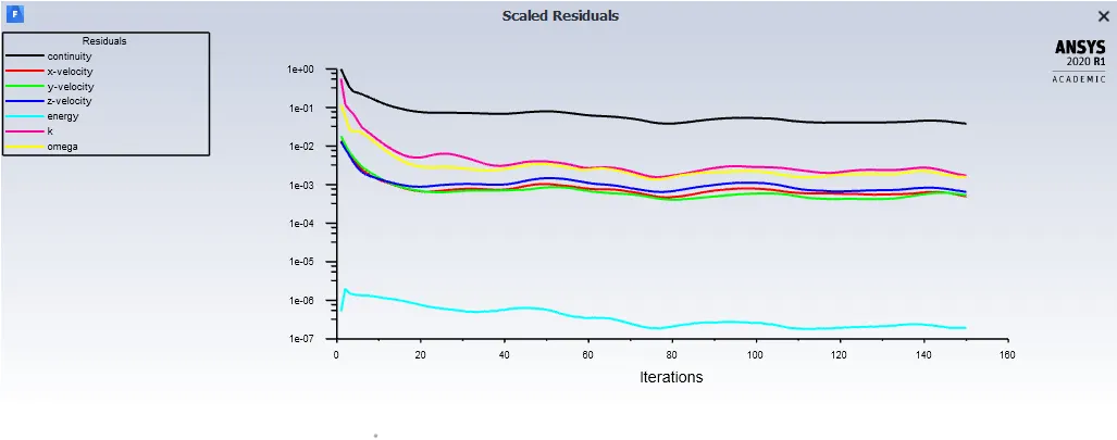
6.Residual Plot:
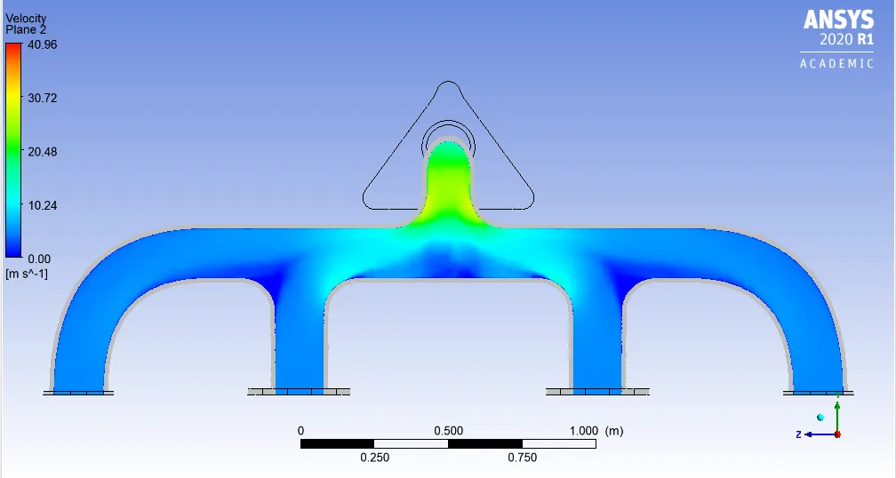
7.Velocity Plot over entire exhaust port(@ Cut plane)
8.Temperature Plot over entire exhaust port(@ Cut plane)
9.Velocity contour Plot over entire exhaust port(@ Cut plane)
10.Temperature contour Plot over entire exhaust port(@ Cut plane)
Description about why and where CHT analysis is used:
CHT analysis as we know study of processes involve heat transfer between solid and fluids.
In engineering real world problems,it is very important tool to understand the natural phenomenon occuring when system consist of solid and fluid comes in contact having different temperatures and amount of heat.
Heat transfer between solid and fluid depends on many factors material used and there heat transfer coefficient,velocity,reynold number,Temperature difference between them.It can be natural or forced convection also adding over CHT which alos affect the heating or cooling of fluid or solid .
CHT analysis is used in Autmobile,Aerospace ,Nuclear,Marine industries and many more.
I would give brief description about use in Marine.
In ship CHT analysis of every machine component is very important,because failure of any even single component can affect the operation of Main engine.
Heat is always generated when combustion takes place in main engine,so for maintaining cylinder liner and piston at certain temperature ,jacket water need to be supplied for cooling , that is also at certain flow rate and temperature.If cooling jacket water temperature is not maintained to a certain temperature then it would not cool the cylinder liner and piston.Which in turn seize the operation of engine after sometime due to higher temperature of liner and piston.
So how much temperature need to be maintained at Jacket cooling water
#Y plus value significance:
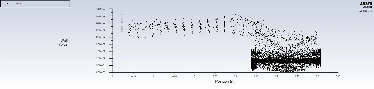
Y plus value for `komegasst` turbulence model is to be maintained less than 5.
Comparision between Exhaust port model base mesh and Refined mesh prove the importance of Y plus value.
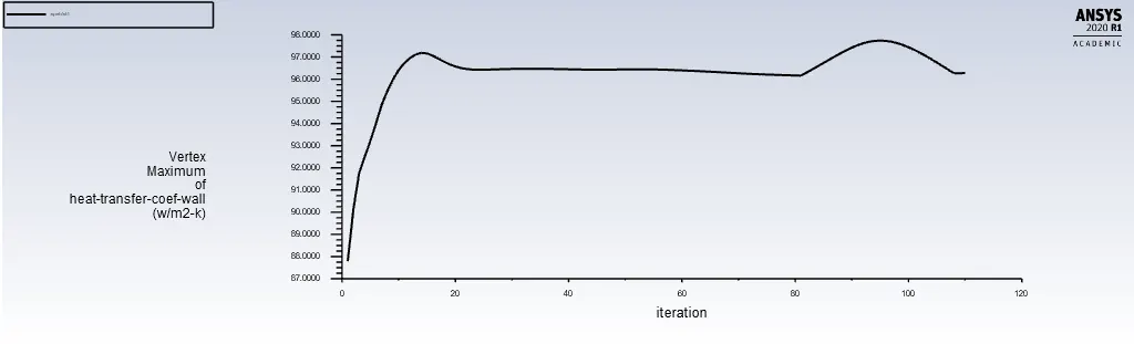
##For Base mesh (Coarse one without inflation layers)
a).Y plus value plot
b).Maximum value plot for Heat Transfer coefficient:
##For refined Mesh (with inflation layers):
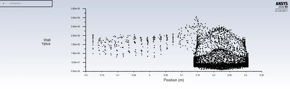
a).Y plus value plot
b).Maximum value plot for Heat Transfer coefficient: 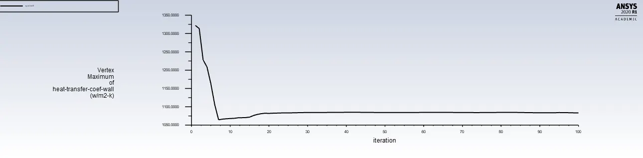
After analysing both the cases Y plus value plot we can see ,as in coarse mesh case Y plus value is
ranging from 10 to 400 over the entire cross section of exhaust port.But in Refined Mesh case Y plus
value ranging from 0.2 to 3 which is required for `komegasst` model for more accurate results.
We can observe the difference between Maximum value of heat transfer coeffcient from both cases.
For coarse mesh having very high Y plus value ,Max. HTC is 97.7 `w/(m2-k)`
and for Refined Mesh having Y plus value in a range required ,Max. HTC is 1083.29 `w/(m2-k)`.
This shows that Y plus value has so much significance in achieving correct results.
##Verification of HTC prediction :
Results obtained from simulation can never be better and accurate than analytical results.
So in CHT analysis ,for verifing HTC value we obtained is correct or not we need to calculate it
analytically through heat transfer equations and formulae.
As given below
h = (kw/DH)*Nu
where kw is the thermal conductivity of the liquid, DH is the Hydraulic diameter, and Nu is the Nusselt
Number which is determined by the following equation:
Nu = 0.023Re0.8Prn
n=0.4;
In this equation, Re is the Reynolds number which equates to:
Re = (m DH)/(μA)
And Pr is the Prandtl number, equating to:
Pr = (Cp* μ)/kw
For the Reynolds number, m is equal to the mass flow rate, and A is a cross sectional area of flow taken
from the tube. For the Prandtl number, Cp is equal to heat capacity (assuming a constant pressure), and
in both equations, μ is the viscosity of the fluid in consideration.
Factors on which accuracy of Prediction depends:
1.Most important is setting up Mesh .
2.Setting up Geometry correctly.
3.Inflation layers thickness and Y plus value.
4.Use of suitable turbulence model .
5.Selection of correct material while setting up case,so that we would be sure while comparing simulation results with analytical results.