Engine kinematics
first we will input the constant gamma, temperature at state 3, pressure & temperature at state 1.
then we have to give the engine geometric parameters ie. bore, stroke, connecting rod length and compression ratio.
then we will calculate swept volume and clearence volume.
from swept volume and clearence volume we will calculate volume at state 1 & 2.
then we will caculate constant for state 2
NOW TO CALCULATE VOLUMETRIC COMPRESSION AT STATE 2 WE WILL PASS THE VALUES OF bore, stroke, con_rod, cr, start_crank,end_crank TO Engine_kinematics function.
then we will calculate pressure compression for state 2.
now we will calculate volume and pressure at state 3.
again we will caculate constant for state 3
NOW TO CALCULATE VOLUMETRIC COMPRESSION AT STATE 3 WE WILL PASS THE VALUES OF bore, stroke, con_rod, cr, start_crank,end_crank TO Engine_kinematics function.
then we will calculate pressure compression for state 3.
now we will calculate volume and pressure at state 4.
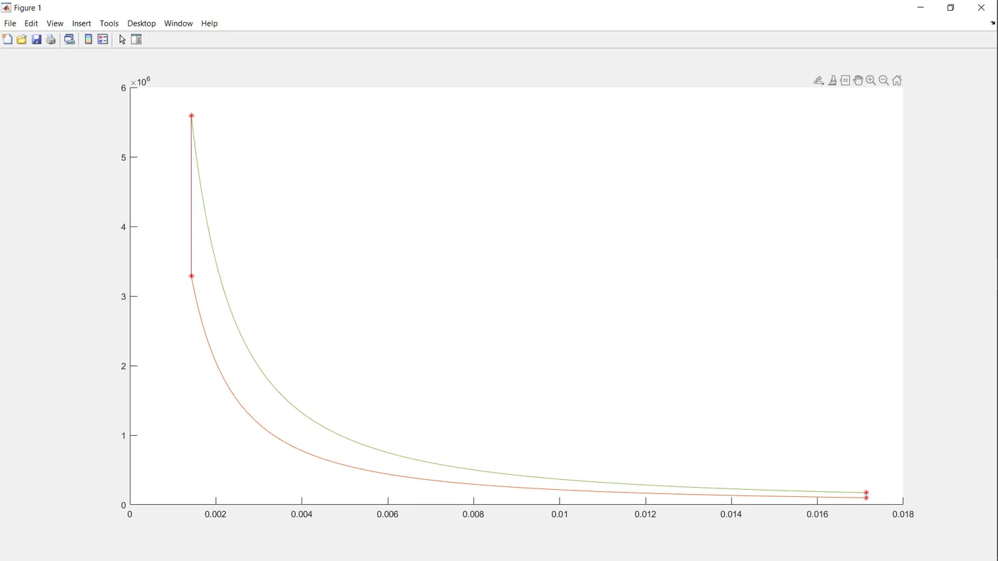
then we will plot the graph.
NOW IN Engine_kinematics function:
first we will calculate crank pin radius.
then we will calculate R which is ratio of aonnecting rod length to crank pin radius.
then we will define theta.
then we will find change of volume inside IC engine using the formula as shown below
clear all;
 close all;
 clc;

 % input
 gamma = 1.4;    % constant
 t3 = 2300;      % temperature at state 3

 %state variables
 p1 =101325;      % pressure at state 1
 t1 = 500;         % temperature at state 1

 % engine geometric parameters
 bore = 0.1;        %
 stroke = 0.1;      %
 con_rod = 0.15;   % connecting rod length
 cr = 12;          % compression ratio

 % calculating the swept volume and clearence volume
 v_swept = (pi/4)*bore*2*stroke;     % volume swept
 v_clearence = v_swept/(cr-1);       % clearence colume

 v1 = v_swept + v_clearence;         % volume at state 1
 v2 = v_clearence;                   % volume at state 2

 % statevariables at state point 2
 p2 = p1*(cr^gamma);                 % pressure at state 2
 t2 = p2*v2*t1/(p1*v1);              % pressure at state 2

 const_c = p1*v1^gamma;
 v_compression = Engine_kinematics(bore, stroke, con_rod, cr, 180, 0);  % to get the values for v_compression we need to call the Engine_kinematics function and have to pass the values
 p_compression = const_c./v_compression.^gamma;                         % pressure expansion at state 2


 %state variable at state point 3
 v3 = v2;                             % pressure at state 3

 p3 = p2*t3/t2;                        % temperature at state 3

 const_c = p3*v3^gamma;
 v_expansion = Engine_kinematics(bore, stroke, con_rod, cr, 0, 180);       % volume expansion at state 3
 p_expansion = const_c./v_expansion.^gamma;                                % pressure expansion at state 3

 % state variables at state point 4
 v4 = v1                             % volume at state 4

 p4 = p3*(v3/v4)^gamma               % pressure at state 4


 % Plotting the curves
 figure(1)
 hold on
 plot (v1,p1,'*','color','r')
 plot(v_compression, p_compression)
 plot (v2,p2,'*','color','r')
 plot (v3,p3,'*','color','r')
 plot(v_expansion, p_expansion)
 plot (v4,p4,'*','color','r')
 plot([v2 v3],[p2 p3])
 plot([v4 v1],[p4 p1])
function[v] = Engine_kinematics(bore, stroke, con_rod, cr, start_crank,end_crank) % getting the values for bore, stroke, con_rod, cr, start_crank,end_crank from another program

a = stroke/2;       % Crank pin radius
R = con_rod/a;      % R is ratio of aonnecting rod length to crank pin radius

v_swept = (pi/4)*bore*2*stroke;   % swept volume
v_clearence = v_swept/(cr-1);     % clearence volume

theta = linspace(start_crank,end_crank,100);   % crank angle

term1 = 0.5*(cr-1);
term2 = R+1 - cosd(theta);
term3 = (R^2 - sind(theta).^2).^0.5;

v= (1+ term1*(term2 - term3)).*v_clearence; % change of volume inside a IC engine

end