Emission characterization of a CAT3410 engine
I. Aim
i. To perform engine sector simulations with both the given pistons: Omega piston and Open-W piston.
ii. To compare the Indicated Mean Effective Pressure (IMEP) and Engine Power for the two pistons.
iii. To compare the emission characteristics (including Soot, `NO_x` and UHC) of the two pistons.
II. Theory
In the current project engine sector simulation is performed for both the given pistons (Omega piston and Open W piston) using the following input files:
i. Surface file for the Open W piston
ii. Piston bowl profile for the Omega piston
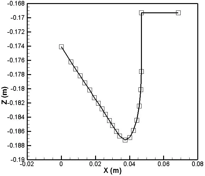
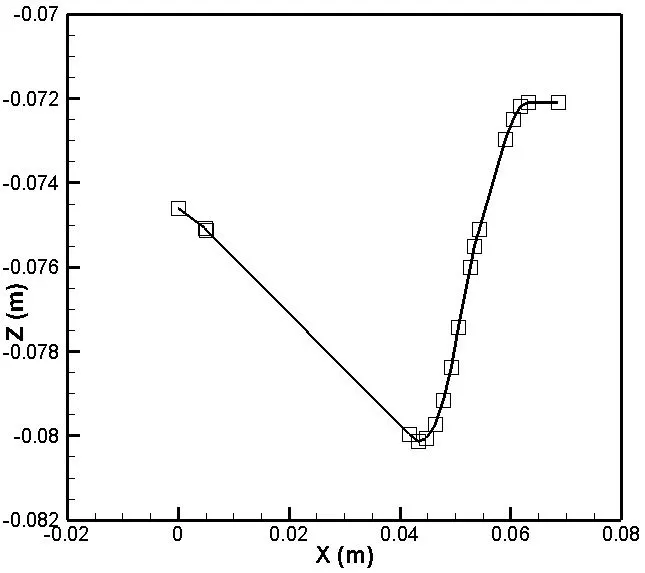
The main advantage of performing a sector simulation, over performing a full 360 deg. simulation, is reduced computational time. However in order to perform such an engine sector simulation, piston bowl profile is required which is extracted from the given surface file using the "Make engine sector surface" tool provided by CONVERGE. The plots attached below show the geometric profiles of the two pistons.
i. Omega piston
ii. Open W piston
Apart from geometric profile of the two pistons the entire case setup remains the same.
In order to make a selection between two or more piston profiles, the different characteristics should be studied and compared. The different types of engine characteristics can be broadly classified as follows:
i. Performance characteristics: Parameters that quantify engine performance are analyzed. Examples include pressure, work etc.
ii. Combustion characteristics: Parameters that indicate the combustion efficiency of the engine are analyzed. Examples include mean temperature, heat release rate (HRR), integrated heat release (IHR) etc.
iii. Emission characteristics: Parameters that quantify the engine emissions are analyzed. Examples include mass of: Soot, `NO_x`, HC, CO etc.
These characteristics should be compared for the different piston profiles. Based on the designer's goal (example: to reduce `NO_x` emission, to increase engine power etc.) the advantages and disadvantages of every piston profile must be weighed against one another to select the best option.
III. Case setup
1. Geometry
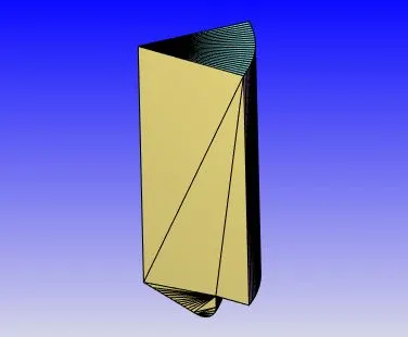
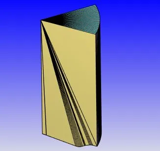
The images attached below show the two geometries used for performing simulations.
i. Omega piston
ii. Open W piston
For both the pistons, the details related to the sector geometry are as follows:
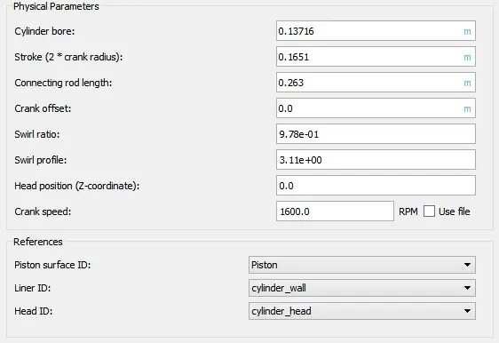
i. Bore: 0.13716m
ii: Stroke: 0.1651m
iii. Connecting rod: 0.263m
iv. Compression ratio: 17.5
v. Sector angle: 45 deg.
2. Application type
Both simulations are defined as crank-angle based IC engine type applications with the following settings:
3. Materials
3.1. Gas simulation
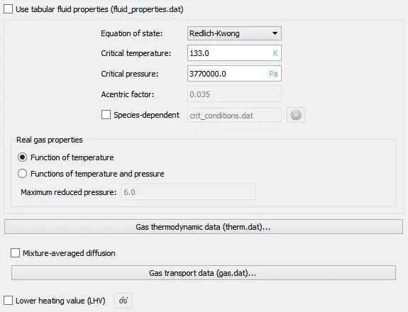
The following settings are used for gas simulation:
3.2. Parcel simulation
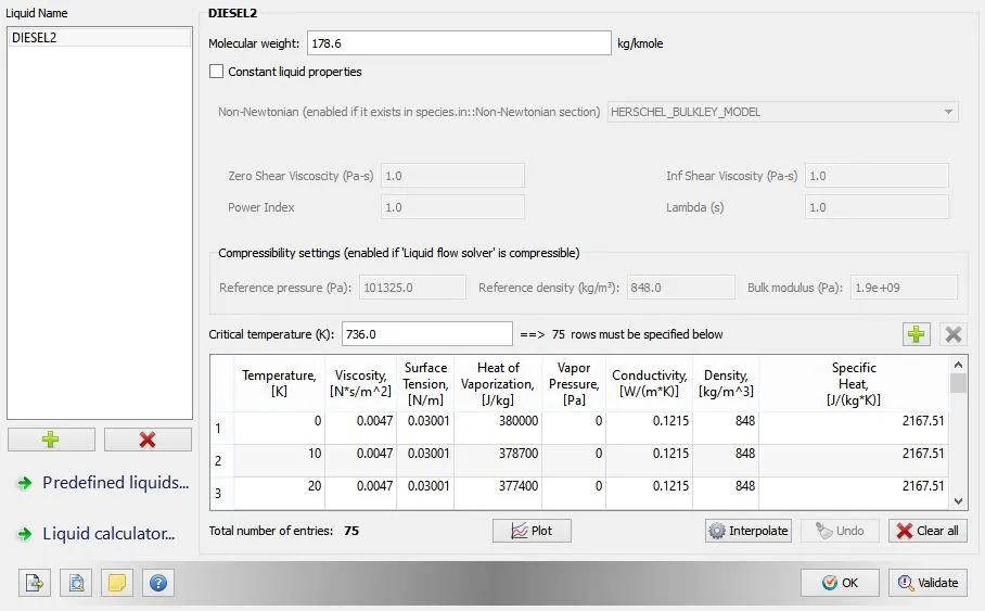
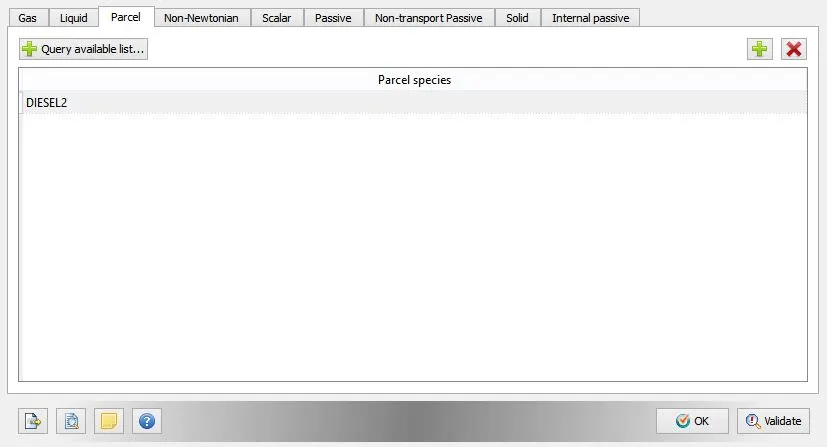
Predefined liquid, DIESEL2, is selected as the parcel species. The following settings are applied for parcel simulation:
3.3. Global transport parameters
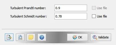
The following global transport parameters are used for both the simulations:
3.4. Reaction mechanism
A reaction mechanism compatible with diesel combustion is used. The mechanism is based on the oxidation of n-heptane. Hence the fuel is n-heptane and the oxidizer is air (77% Nitrogen and 23% Oxygen by mass fractions). The reaction mechanism is imported from mech.dat file. The image attached below shows the various species involved in the different chemical reactions proposed in mech.dat.
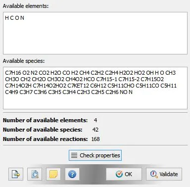
The thermophysical properties of the species mentioned above are available in the therm.dat file.
3.5. Species
Any species which is not included in mech.dat has to be defined explicitly. In the current simulation only gas species and parcel species are present and all the gas species are already included in mech.dat. Hence the remaining parcel species are defined as follows:
4. Simulation Parameters
4.1. Run parameters
Solver: Transient
Temporal type: Crank angle-based engine simulation
Simulation mode: Full hydrodynamic
Gas flow solver: Compressible
Liquid flow solver: Incompressible
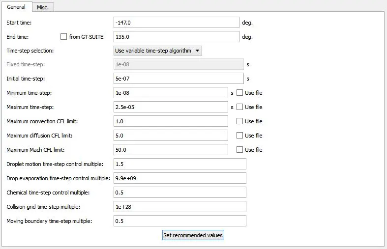
4.2. Simulation time parameters
4.3. Solver parameters
Navier-Stokes solver scheme: PISO
Navier-Stokes solver type: Density-based
5. Boundary Conditions
The following boundary conditions are imposed on the different boundaries:
i. Piston:
Boundary Type: WALL
Velocity Boundary Condition:
Wall motion type: Translating
Surface movement: MOVING
Law of wall; Piston motion
Temperature Boundary Condition:
Law of wall; 553K
Heat model:
Global
Turbulent Kinetic Energy Boundary Condition:
Zero normal gradient
Turbulent Dissipation Boundary Condition:
Wall model
Region Name: In_cylinder_region
ii. Front_face:
Boundary Type: PERIODIC
Periodic Type: Stationary
Periodic Shape: Rotational
Angle: 45 deg.
Rotation Axis: `0hat{i}+0hat{j}+1hat{k}`
Rotation Center: (0,0,0)
Matching Boundary: Back_face
Region Name: In_cylinder_region
iii. Back_face:
Boundary Type: PERIODIC
Periodic Type: Matched Boundary
Matching Boundary: Front_face
Region Name: In_cylinder_region
iv. cylinder_wall:
Boundary Type: WALL
Velocity Boundary Condition:
Wall motion type: Stationary
Surface movement: FIXED
Law of wall
Temperature Boundary Condition:
Law of wall; 433K
Heat model:
Global
Turbulent Kinetic Energy Boundary Condition:
Zero normal gradient
Turbulent Dissipation Boundary Condition:
Wall model
Region Name: In_cylinder_region
v. cylinder_head:
Boundary Type: WALL
Velocity Boundary Condition:
Wall motion type: Stationary
Surface movement: FIXED
Law of wall
Temperature Boundary Condition:
Law of wall; 523K
Heat model:
Global
Turbulent Kinetic Energy Boundary Condition:
Zero normal gradient
Turbulent Dissipation Boundary Condition:
Wall model
6. Initial Conditions and Events
A volumetric region is created using the boundaries defined above, and the following initial conditions are applied:
Velocity: 0
Temperature: 355K
Pressure: 197000Pa
Turbulent Kinetic Energy: 62.0271 `m^2//s^2`
Turbulent Dissipation: 17183.4 `m^2//s^3`
Mass fraction of `CO_2`: 0.0014304
Mass fraction of `H_2O`: 0.0006296
Mass fraction of `N_2`: 0.76765
Mass fraction of `O_2`: 0.23029
Mass of Hiroy Soot: 0
Mass fraction of `NO_x`: 0
7. Physical Models
7.1. Spray modeling
7.1.1. Parcel distribution: Cluster parcels near cone center
7.1.2. Turbulent dispersion: O'Rourke model
7.1.3. Evaporation model: Frossling model
7.1.4. Evaporation source: Source specified species
7.1.5. Maximum radius for ODE droplet heating: 1000m (A large number is selected on purpose to avoid solving the ODE for droplet heating. This speeds up the solution procedure)
7.1.6. Collision model: NTC collision model
7.1.7. Collision outcomes: Post collision outcomes
7.1.8. Drop drag mode: Dynamic drop drag
7.1.9. Spray-wall interaction model: Rebound/slide
7.1.10. Injected parcel species: DIESEL2
7.1.11. Mass fraction of the injected species: 1.0
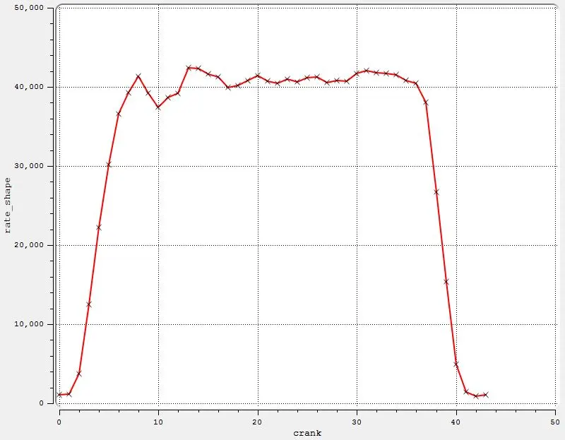
7.1.12. Rate-shape: The following rate-shape is adopted for the injection process:
7.1.13. Instability models: Kelvin-Helmholtz (KH) model, Rayleigh-Taylor (RT) model, Discharge coefficient model
7.1.14. Injection temporal type: CYCLIC
7.1.15. Cyclic period: 720 deg.
7.1.16. Start of injection: -9 deg.
7.1.17. Injection duration: 21 deg.
7.1.18. Total injected mass: `2.70167times10^-5 Kg`
7.1.19. Total number of injected parcels (per nozzle): 50000
7.1.20. Injection drop distribution: Predefined, Blob (specified nozzle diameter)
7.1.21. Temperature: 341K
7.1.22. Injection spray type: Solid cone spray
7.1.23. Nozzle diameter: 0.000259m
7.1.24. Circular injection radius: 0.0001295m
7.1.25. Spray cone angle: 9 deg.
7.1.26. Location and orientation of nozzles:
Nozzle radial position: 0.0009700000000000001m
Nozzle axial position: 0.0
Nozzle azimuthal position: 0.0
Tilt angle in the xy plane: 0.0
Tilt angle in the xz plane: 62.5 deg.
Coordinate of injector (x, y, z): (0, 0, -0.0032208)
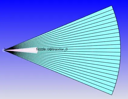
The image attached below shows the top view of the engine sector including the injector.
7.2. Combustion modeling
SAGE combustion model is used with the following settings:
Fuel species name: C7H16
Temporal type: SEQUENTIAL
Cyclic period: 720 deg.
Start time: -10 deg.
End time: 135 deg.
Regions: Not region-dependent
Combustion temperature cutoff: 600K
Minimum HC species mole fraction: 1e-8
Adaptive zoning: Enabled
Temperature bin size: 5K
Reaction ratio bin size: 0.05
Emissions modeling: Enabled
Thermal `NO_x` model (Extended Zeldovich): Enabled
O/OH models for the thermal `NO_x`: Equilibrium assumption
Mass scaling factor converting NO to `NO_x`: 1.533
Hiroyasu-NSC soot model: Enabled
Soot pre-exponential formation rate factor: 350(s*bar^0.5)^-1
Soot activation energy in the formation rate: 12500cal/gmol
Soot particle diameter: 2.5e-6cm
Soot oxidation rate factor: 1.0
Soot density: 2.0g/cm^3
Formation species: Total hydrocarbons
7.3. Turbulence modeling
RNG `K-epsilon` model is used to capture turbulence.
8. Grid Control
8.1. Base grid
dx=dy=dz=0.004m
8.2. Adaptive Mesh Refinement
The following settings are used for AMR:
AMR Group 1: Velocity
Minimum cells: 1
Maximum cells: 2000000
Region: In_cylinder_region
Embed type: Sub-Grid Scale (SGS)
Timing control type: PERMANENT
Maximum embedding level: 2
Minimum grid size: (Base grid size)/2^(Embedding level)=(Base grid size)/2^2=(Base grid size)/4=0.001m
Sub-Grid criterion: 2m/s
Use AMR when parcel count exceeds: 50
AMR Group 1: Temperature
Minimum cells: 1
Maximum cells: 2000000
Region: In_cylinder_region
Embed type: Sub-Grid Scale (SGS)
Timing control type: SEQUENTIAL
Start: -12 deg.
End: 180 deg.
Maximum embedding level: 2
Minimum grid size: (Base grid size)/2^(Embedding level)=(Base grid size)/2^2=(Base grid size)/4=0.001m
Sub-Grid criterion: 5K
8.3. Fixed embedding
Fixed embedding is applied at specific locations as follows:
i. Embedding 1:
Entity type: NOZZLE
Mode: SEQUENTIAL
Scale: 2
Resultant grid size: (Base grid size)/2^(Embed scale)=(Base grid size)/2^2=(Base grid size)/4=0.001m
Start time: -12 deg.
End time: 15 deg.
Radius 1: 0.001m
Radius 2: 0.003m
Length: 0.01m
ii. Embedding 2:
Entity type: BOUNDARY
Boundary ID: Piston
Mode: SEQUENTIAL
Scale: 1
Embed Layers: 1
Resultant grid size: (Base grid size)/2^(Embed scale)=(Base grid size)/2^1=(Base grid size)/2=0.002m
Start time: -20 deg.
End time: 180 deg.
iii. Embedding 3:
Entity type: BOUNDARY
Boundary ID: cylinder_head
Mode: SEQUENTIAL
Scale: 1
Embed Layers: 1
Resultant grid size: (Base grid size)/2^(Embed scale)=(Base grid size)/2^1=(Base grid size)/2=0.002m
Start time: -20 deg.
End time: 180 deg.
IV. Results
1. Performance characteristics
1.1. Cylinder pressure
The figure attached below shows the cylinder pressure as a function of crank angle for the two pistons.
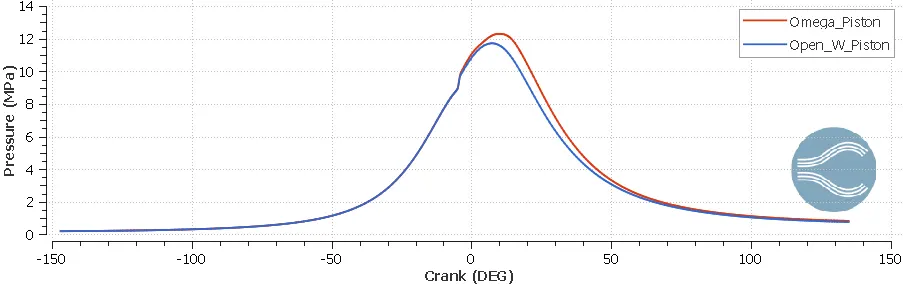
The plot shows that around -100 deg. crank angle the cylinder pressure begins to increase. This is because of the beginning of compression stroke. As the piston moves towards the TDC, the cylinder pressure keeps increasing and finally around -5 deg. crank angle the combustion process begins due to which the slope of the curve suddenly increases. The cylinder pressure peaks around 5 deg. crank angle indicating that the piston has reached the TDC. The compression stroke is followed by expansion stroke (power stroke) during which the high pressure generated due to combustion pushes the piston with a tremendous force. As the piston moves towards the BDC, the cylinder pressure falls due to expansion. It is evident that both the pistons generate a similar trend. However the peak pressure in case of Omega piston is higher than that in case of Open W piston. Also it can be seen that since the trend corresponding to the Omega piston always lies above the trend corresponding to the Open W piston, the average pressure is higher in case of Omega piston.
1.2. Work/Power
The figure attached below shows the cylinder pressure as a function of volume for both the pistons.
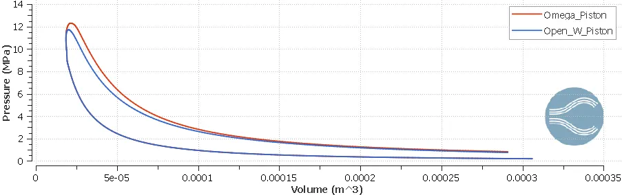
The graph clearly shows that the area under the PV diagram is greater for Omega piston, which signifies that the net work delivered by the engine is greater in case of Omega piston. Power delivered by a four-stroke IC engine is given by:
`P=WtimesN/2times1/60` where N is the engine RPM
For both the pistons the engine RPM is same (1600RPM) and hence the engine delivers more power in case of Omega piston.
The Indicated Mean Effective Pressure (IMEP) is given by:
IMEP=(Net Work delivered by the engine)/(Swept Volume)
Since the swept colume is same for the two pistons, IMEP is greater in case of Omega piston.
1.3. Engine performance parameters
In this section the engine performance parameters, calculated using the CONVERGE tool "Engine Performance", are compared for the two pistons.
i. Omega piston
(a) Gross Work: 481.431J
(b) IMEP: 197237Pa
(c) Power delivered by the engine:
`P=WtimesN/2times1/60=481.431Jtimes(1600RPM)/2times1/(60s//min)=6419.08W=6.42KW`
ii. Open W piston
(a) Gross Work: 415.259J
(b) IMEP: 170127Pa
(c) Power delivered by the engine:
`P=WtimesN/2times1/60=415.259Jtimes(1600RPM)/2times1/(60s//min)=5536.787W=5.54KW`
The Gross Work, engine power and IMEP are greater in case of Omega engine which agrees with our analysis of the PV diagram.
2. Combustion characteristics
2.1. Temperature
The figure attached below shows the mean (volume-averaged) temperature in the cylinder as a function of crank angle for both the pistons.
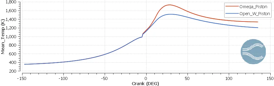
Similar to pressure the mean temperature in the cylinder initially increases due to compression stroke. Suddenly the rate of increase of mean temperature increases around -5 deg. due to the start of combustion process. The mean temperature peaks when the piston is at the TDC and subsequently it falls during the expansion stroke. It is evident that the peak mean temperature in case of Omega piston is much greater than that in case of Open W piston. This may be due to incomplete combustion of fuel in case of Open W piston. However more results, such as soot and CO formation, are needed to confirm this hypothesis.
2.2. Heat Release Rate (HRR)
The figure attached below shows the Heat Release Rate (HRR) as a function of crank angle for the two pistons.
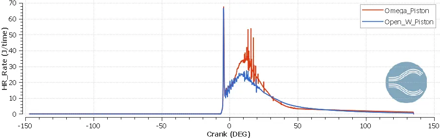
The plot shows that the HRR for Open W piston is much lower than that for Omega piston. This again may be due to incomplete combustion of fuel in case of Open W piston. However as mentioned earlier more data is required to be sure.
2.3. Integrated Heat Release (IHR)
The figure attached below shows the Integrated Heat Release (IHR) as a function of crank angle for the two pistons.
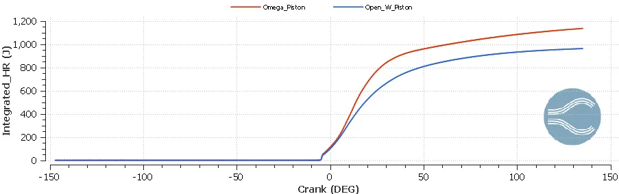
Integrated Heat Release represents the total amount of heat released during the combustion process. The plot clearly shows that IHR is greater for Omega piston. Combustion efficiency is an important parameter that quantifies the ability of an engine to convert the chemical energy of the fuel into thermal energy.
`eta_(combustion)=(IHR)/(m_(fuel)timesLCV)` where:
`m_(fuel)`: Mass of the injected fuel=2.70167e-05Kg
`LCV`: Lower Calorific Value=42.6MJ/Kg
For Omega piston:
`IHR`=1137.06J
Hence:
`eta_(combustion)=(1137.06J)/(2.70167times10^-5Kg times 42.6times10^6J//Kg)=0.988`
For Open W piston:
`IHR`=963.32J
Hence:
`eta_(combustion)=(963.32J)/(2.70167times10^-5Kg times 42.6times10^6J//Kg)=0.837`
Hence the combustion efficiency of Omega piston is higher. Another way to compare the combustion efficiencies of the two pistons is to estimate the mass of extra fuel required in case of Open W piston to release the same amount of heat as that released in case of Omega piston, over a particular number of crankshaft revolutions.
Let us assume that for both the pistons, the engine crankshaft revolves for 1000 revolutions. Since the engine is four-stroke, combustion occurs once in every two revolutions. Hence:
Total amount of heat released in case of Omega piston:
`Q_1=1137.06Jtimes500=568530J=568.530KJ`
Total amount of heat released in case of Open W piston:
`Q_2=963.32Jtimes500=481660J=481.660KJ`
Therefore the mass of extra fuel required in case of Open W piston to release the same amount of heat as that released in case of Omega piston, over 1000 crankshaft revolutions:
`m_(extra-fuel)=(Q_1-Q_2)/(LCV)=(568.530KJ-481.660KJ)/(42.6times10^6J//Kg)=2.04times10^-3Kg=2.04mg`
2.4. Mass of Gaseous fuel
The figure attached below shows the mass of the gaseous fuel present in the cylinder as a function of crank angle for both the pistons.
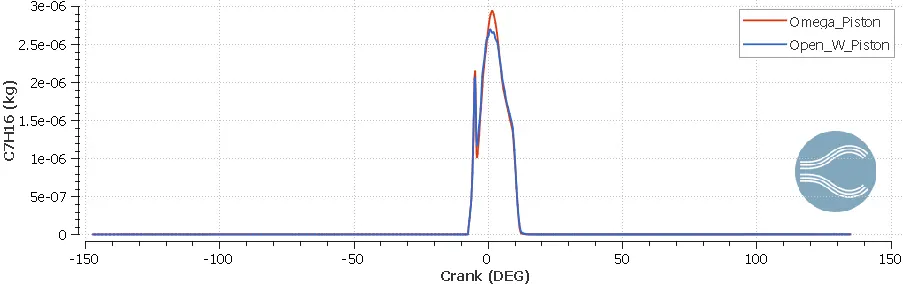
The plot shows that more amount of gaseous fuel is present in the cylinder in case of Omega piston. This may be due to better atomization of fuel spray, which leads to more evaporation and more heat release during combustion. In order to gain a better insight, the spray-wall interaction in case of both pistons must be observed.
2.5. Spray-wall interaction
The animation attached below shows the interaction between fuel spray and piston head in case of both the pistons.
It can be seen that in case of Open W piston the fuel spray does not have enough time to atomize sufficiently before it impinges the piston head. Due to inadequate atomization, a lot of fuel does not vaporize and mix well with air which leads to incomplete combustion resulting in lesser heat release and lower mean temperature in the cylinder.
3. Emission characteristics
3.1. Mass of Hiroy Soot
The figure attached below shows the mass of Hiroy Soot in the cylinder as a function of crank angle for the two pistons.
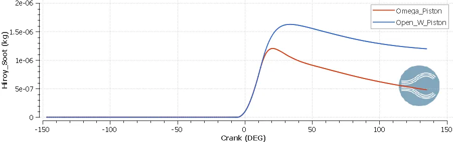
The plot shows that a significantly higher amount of soot is produced in case of Open W piston due to incomplete combustion of fuel. At the end of the cycle:
Mass of soot in the cylinder in case of Omega piston: `4.81times10^-7Kg`
Mass of soot in the cylinder in case of Open W piston: `1.199times10^-6Kg`
The animation attached below shows the mass fraction contours of Hiroy Soot as a function of crank angle for both the pistons.
3.2. Mass of CO
The figure attached below shows the mass of CO in the cylinder as a function of crank angle for both the pistons.
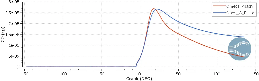
The plot shows that a significantly higher amount of CO is produced in case of Open W piston due to incomplete combustion. At the end of the cycle:
Mass of CO in the cylinder in case of Omega piston: `4.58times10^-6Kg`
Mass of CO in the cylinder in case of Open W piston: `1.38times10^-5Kg`
The animation attached below shows the mass fraction contours of CO as a function of crank angle for both the pistons.
3.3. Mass of HC
The figure attached below shows the mass of HC in the cylinder as a function of crank angle for both the pistons.
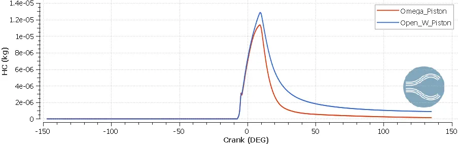
The plot shows that a higher amount of unburnt fuel is remaining in the cylinder in case of Open W piston due to incomplete combustion of fuel. At the end of the cycle:
Mass of HC in the cylinder in case of Omega piston: `1.41times10^-7Kg`
Mass of HC in the cylinder in case of Open W piston: `8.81times10^-7Kg`
3.4. Mass of `CO_2`
The figure attached below shows the mass of `CO_2` in the cylinder as a function of crank angle for both the pistons.
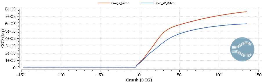
The plot shows that a lesser amount of `CO_2` is produced in case of Open W piston. This is because of incomplete combustion due to which CO is produced instead of `CO_2`. At the end of the cycle:
Mass of `CO_2` in the cylinder in case of Omega piston: `7.63times10^-5Kg`
Mass of `CO_2` in the cylinder in case of Open W piston: `5.98times10^-5Kg`
The animation attached below shows the mass fraction contours of `CO_2` as a function of crank angle for both the pistons.
3.5. Mass of `NO_x`
The figure attached below shows the mass of `NO_x` in the cylinder as a function of crank angle for both the pistons.
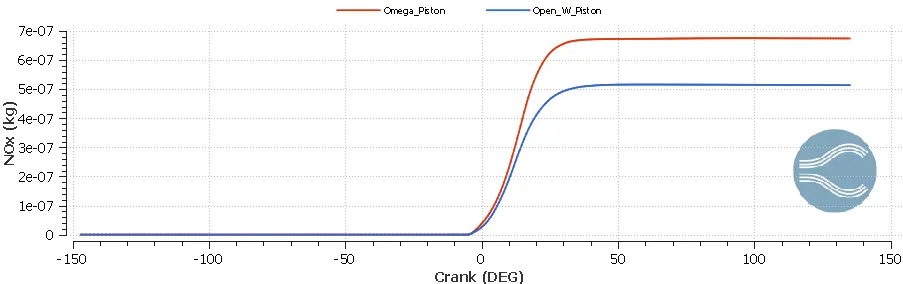
The plot shows that a higher amount of `NO_x` is produced in case of Omega piston. This can be attributed to higher mean temperature in the cylinder (since `NO_x` formation occurs at higher temperatures). At the end of the cycle:
Mass of `NO_x` in the cylinder in case of Omega piston: `6.74times10^-7Kg`
Mass of `NO_x` in the cylinder in case of Open W piston: `5.14times10^-7Kg`
The animation attached below shows the mass fraction contours of `NO_x` as a function of crank angle for both the pistons.
V. Conclusion
The following conclusions can be drawn based on the comparative study between Omega piston and Open W piston:
1. The performance characteristics of Omega piston are better than Open W piston. In other words with Omega piston the engine delivers more work/power.
2. The combustion characteristics of Omega piston are better than Open W piston. In other words in case of Omega piston more amount of heat is released from the same amount of fuel as compared to Open W piston.
3. Since the mean temperature in the cylinder is higher in case of Omega piston, it produces more `NO_x`.
4. Due to incomplete combustion of fuel in case of Open W piston, it produces greater amounts of soot, CO and HC but lesser amount of `CO_2`.
5. Based on the comparative study, Omega piston is the obvious choice as it has better performance, better combustion efficiency and better emission characteristics. Open W piston is the better choice only if one aims to reduce the `NO_x` emissions.