Drafting of various geometries using Chamfer, Fillet tool in AutoCad
1. Decimal
Aim:
Sketch the AutoCAD drawing using the decimal units.
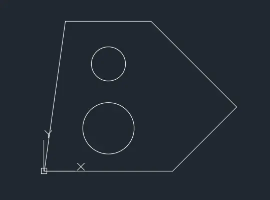
I. In command prompt type (startup:1)
II. Then file>new
III. Then create new drawing window select metric in default settings
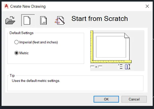
IV. In advanced setup in units check on the decimal,angle in degrees, then ok
V. In command prompt type (L) where line command is woken
VI. In command prompt type (specify first point: 0,0)
VII. In command prompt type (next point: @3<0)
VIII. In command prompt type (next point: @2.12<45) (i.e.,180-135=45)
IX. In command prompt type (next point: @2.83<135) (i.e,90+45=135)
X. In command prompt type (next point: @2<180)
XI. In command prompt type (next point: c)
XII. In command prompt type (CI) where circle command is woken
XIII. In command prompt type (specify centre point: 1.5,1)
XIV. In command prompt type (radius:0.6)
XV. In command prompt type (CI) where circle command is woken
XVI. In command prompt type (specify centre point: 1.5,2.5)
XVII. In command prompt type (radius:0.4)
XVIII. Enter
Result:
Given drawing was drawn in AutoCAD using decimal units.
2. Architectural
Aim:
Sketch the AutoCAD drawing using the Architectural units.
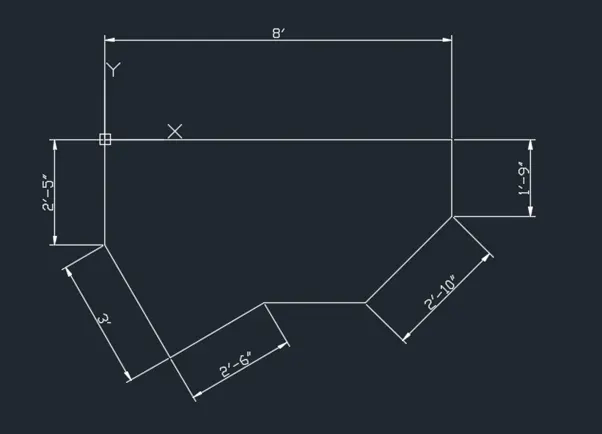
I. In command prompt type (startup:1)
II. Then file>new
III. Then create new drawing window select metric in default settings
IV. In advanced setup in units check on the architectural, angle in degrees, then ok
V. In command prompt type (L) where line command is woken
VI. In command prompt type (specify first point: 0’,0’)
VII. Switch on the polar tracking of 45,90,135
VIII. Now from start point place cursor at 45-degree tracking and type 2’-10’’ enter in command prompt
IX. Next place cursor at 90-degree tracking and type 1’-9’’ enter in command prompt
X. Next place cursor at 180-degree tracking and type 8’enter in command prompt
XI. Next place cursor at 270-degree tracking and type 2’-5’’ enter in command prompt
XII. Now change the polar tracking to 30,60,90
XIII. Next place cursor at 300-degree tracking and type 3’ enter in command prompt
XIV. Next place cursor at 30-degree tracking and type 2’-6’’ enter in command prompt
XV. In command prompt type (next point: c)
XVI. Enter
Result:
Given drawing was drawn in AutoCAD using architectural units
3. Engineering
Aim:
Sketch the AutoCAD drawing using the engineering units.
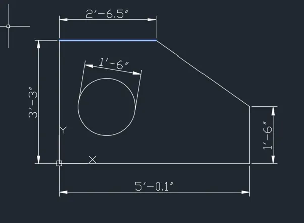
I. In command prompt type (startup:1)
II. Then file>new
III. Then create new drawing window select metric in default settings
IV. In advanced setup in units check on the architectural, angle in degrees, then ok
V. In command prompt type (L) where line command is woken
VI. In command prompt type (specify first point: 0’,0’)
VII. Switch on the polar tracking of 45,90,135
VIII. Now from start point place cursor at 0-degree tracking and type 5’-10” enter in command prompt
IX. Next place cursor at 90-degree tracking and type 1’-6” enter in command prompt
X. Next from 0,0 place cursor at 90-degree tracking and type 3’-3” enter in command prompt
XI. Next place cursor at 0-degree tracking and type 2’-6.5” enter in command prompt
XII. Next snap the both the end point
XIII. In command prompt type (CI) where circle command is woken
XIV. In command prompt type (specify centre point: 1’-3”,1’-6”)
XV. In command prompt type (diameter:1’-6”)
XVI. Enter
Result:
Given drawing was drawn in AutoCAD using engineering units
4. P4
Aim:
Sketch the AutoCAD drawing using the decimal units.
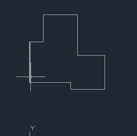
I. In command prompt type (startup:1)
II. Then file>new
III. Then create new drawing window select metric in default settings
IV. In advanced setup in units check on the decimal,angle in degrees, then ok
V. In command prompt type (L) where line command is woken
VI. In command prompt type (specify first point: 0,0.5)
VII. In command prompt type (next point: @3<90)
VIII. In command prompt type (next point: @1<0)
IX. In command prompt type (next point: @2<90)
X. In command prompt type (next point: @2.5<0)
XI. In command prompt type (next point: @3<270)
XII. In command prompt type (next point: @2<0)
XIII. In command prompt type (next point: @2.5<270)
XIV. In command prompt type (next point: @2.5<180)
XV. In command prompt type (next point: @0.5<90)
XVI. In command prompt type (next point: c)
XVII. Enter
Result:
Given drawing was drawn in AutoCAD using decimal units.
5. P5
Aim:
Sketch the AutoCAD drawing using the decimal units
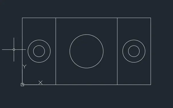
I. In command prompt type (startup:1)
II. Then file>new
III. Then create new drawing window select metric in default settings
IV. In advanced setup in units check on the decimal, angle in degrees, then ok
V. In command prompt type (L) where line command is woken
VI. In command prompt type (specify first point: 0,0)
VII. In command prompt type (next point: @6<90)
VIII. In command prompt type (next point: @11.5<0)
IX. In command prompt type (next point: @6<270)
X. In command prompt type (next point: c)
XI. Enter
XII. In command prompt type (o) offset, type offset distance as 3 select corner line and do inward offset
XIII. In command prompt type (CI) where circle command is woken
XIV. In command prompt type (specify centre point: 5.75,3)
XV. in command prompt type (diameter:3)
XVI. enter
XVII. In command prompt type (CI) where circle command is woken
XVIII. In command prompt type (specify centre point: 1.5,3)
XIX. in command prompt type (diameter:1)
XX. enter
XXI. In command prompt type (o) offset, type offset distance as 0.5 select circle and offset it outside the circle.
XXII. In command prompt type (co)copy select the both circles last drawn and write @8.5<0
XXIII. Enter
Result:
Given drawing was drawn in AutoCAD using decimal units and usage of copy and offset tool.
6. P6
Aim:
Sketch the AutoCAD drawing using the decimal units
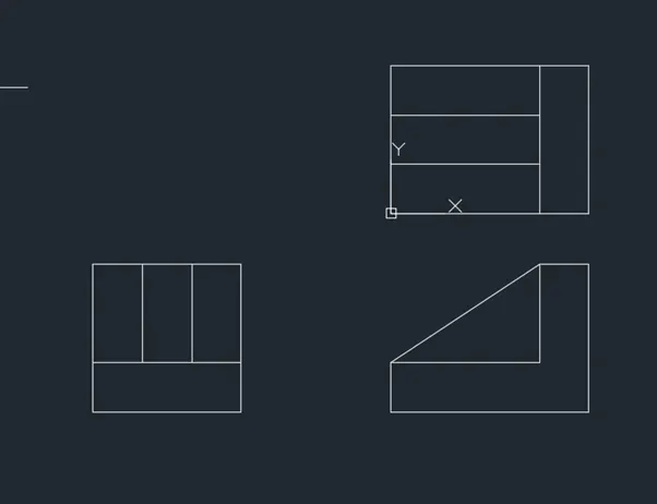
I. In command prompt type (startup:1)
II. Then file>new
III. Then create new drawing window select metric in default settings
IV. In advanced setup in units check on the decimal, angle in degrees, then ok
V. In command prompt type (L) where line command is woken
VI. In command prompt type (specify first point: 0,0)
VII. In command prompt type (next point: @1.5<90)
VIII. In command prompt type (next point: @2<0)
IX. In command prompt type (next point: @1.5<270)
X. In command prompt type (c)
XI. Enter
XII. In command prompt type (o)specify distance as 0.5 and select right side line and offset it inside
XIII. Enter
XIV. In command prompt type (o)specify distance as 0.5 and select top side line and offset it 2 times to bottom
XV. Enter
XVI. In command prompt type (tr) select all objects and press enter and then fence the line which is not required
XVII. Enter
XVIII. In command prompt type (co) copy the outer two lines(right and bottom line) of the above rectangle
XIX. In command prompt type (o)specify distance as 0.5 and select right side line and offset it inside
XX. Select bottom side line and offset it top
XXI. Enter
XXII. With line command join the edges also draw the inclined line
XXIII. enter
XXIV. In command prompt type (tr) select all objects and press enter and then fence the line which is not required
XXV. Enter
XXVI. Now with help of the copy select the first full diagram and drag to another place
XXVII. Select rotate option and select thde 3rd drawing and select corner as the base point and rotate it by 270 degree
XXVIII. In command prompt type (o)specify distance as 0.5 and select top side line and offset it 2 times to bottom
XXIX. Enter
XXX. In command prompt type (tr) select all objects and press enter and then fence the line which is not required
XXXI. Erase the top line
XXXII. Enter
Result:
Given drawing was drawn in AutoCAD using decimal units and usage of copy, trim and offset tool.
7. P7
Aim:
Sketch the AutoCAD drawing using the decimal units and fillet command.
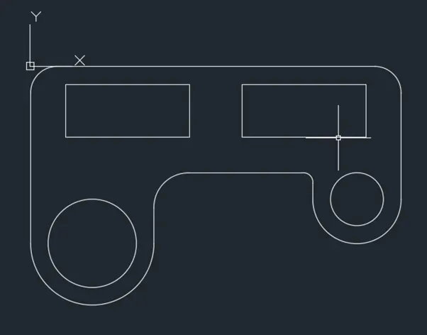
I. In command prompt type (startup:1)
II. Then file>new
III. Then create new drawing window select metric in default settings
IV. In advanced setup in units check on the decimal, angle in degrees, then ok
V. In command prompt type (L) where line command is woken
VI. In command prompt type (specify first point: 0,0)
VII. In command prompt type (next point: @210<0)
VIII. In command prompt type (next point: @75<270)
IX. In command prompt type (next point: @50<180)
X. In command prompt type (next point: @15<90)
XI. In command prompt type (next point: @80<180)
XII. In command prompt type (next point: @40<270)
XIII. In command prompt type (next point: @70<180)
XIV. In command prompt type (next point: c)
XV. Enter
XVI. In command prompt type (next point: f enter r enter) fillet and radius command: 15 select first and next line to fillet at both the top corners
XVII. Respectively with the given radius fillet the lines required
XVIII. In command prompt type (CI) where circle command is woken
XIX. In command prompt type (specify centre point: 35, -100)
XX. in command prompt type (diameter:50)
XXI. enter
XXII. In command prompt type (CI) where circle command is woken
XXIII. In command prompt type (specify centre point: 185,-75)
XXIV. in command prompt type (diameter:30)
XXV. enter
XXVI. In command prompt type (rec) where rectangle command is woken
XXVII. In command prompt type (specify first point: 20,-40)
XXVIII. in command prompt type (next point: @70,30)
XXIX. enter
XXX. In command prompt type (rec) where rectangle command is woken
XXXI. In command prompt type (specify first point: 120, -40)
XXXII. in command prompt type (next point: @70,30)
XXXIII. enter
Result:
Given drawing was drawn in AutoCAD using decimal units and usage of circle, rectangle and fillet tool.
8. P8
Aim:
Sketch the AutoCAD drawing using the decimal units and fillet command.
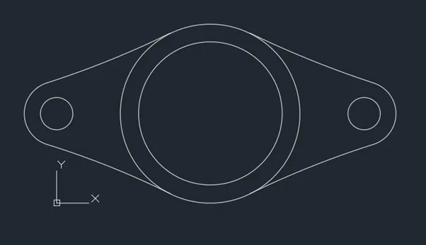
I. In command prompt type (startup:1)
II. Then file>new
III. Then create new drawing window select metric in default settings
IV. In advanced setup in units check on the decimal, angle in degrees, then ok
V. In command prompt type (CI) where circle command is woken
VI. In command prompt type (specify centre point: 4.275,2.5)
VII. in command prompt type (diameter:5)
VIII. enter
IX. In command prompt type (CI) where circle command is woken
X. In command prompt type (specify centre point: 4.275, 2.5)
XI. in command prompt type (diameter:4)
XII. enter
XIII. In command prompt type (specify centre point: 0,2.5)
XIV. in command prompt type (diameter:0.9)
XV. enter
XVI. In command prompt type (CI) where circle command is woken
XVII. In command prompt type (specify centre point: 0, 2.5)
XVIII. in command prompt type (radius:0.9)
XIX. enter
XX. copy the last two circles and in command prompt type (next point: @8.55<0)
XXI. enter
XXII. select the fillet command in home tab and select the centre circle and end circle to form fillet and trim the unwanted lines.
Result:
Given drawing was drawn in AutoCAD using decimal units and usage of circle and fillet tool.
9. P9
Aim:
Sketch the AutoCAD drawing using the Architectural units.
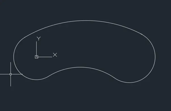
I. In command prompt type (startup:1)
II. Then file>new
III. Then create new drawing window select metric in default settings
IV. In advanced setup in units check on the architectural, angle in degrees, then ok
V. In command prompt type (c) circle
VI. In command prompt type (specify centre point: 0,0)
VII. in command prompt type (radius:8’)
VIII. enter
IX. In command prompt type (CI) where circle command is woken
X. In command prompt type (specify centre point: 32’6”, 0)
XI. in command prompt type (radius:9’)
XII. enter
XIII. In command prompt type (next point: f enter r enter) fillet and radius command: 20’10” select both circle at bottom
XIV. In command prompt type (next point: f enter r enter) fillet and radius command: 41’8” select both circle at top
XV. Trim the unwanted lines
Result:
Given drawing was drawn in AutoCAD using decimal units and usage of circle and fillet tool.
10. P10
aim:
Sketch the AutoCAD drawing using the decimal units and trim command
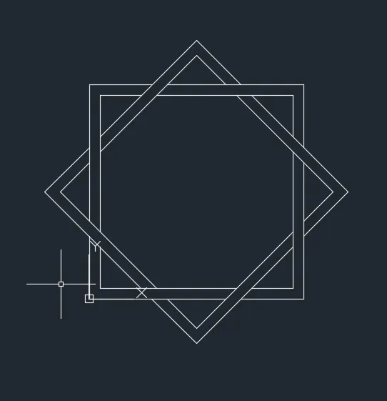
I. In command prompt type (startup:1)
II. Then file>new
III. Then create new drawing window select metric in default settings
IV. In advanced setup in units check on the decimal, angle in degrees, then ok
V. In command prompt type (rec) where rectangle command is woken
VI. In command prompt type (specify first point: 0, 0)
VII. in command prompt type (next point: 5,5)
VIII. enter
IX. In command prompt type (o:0.25) offset whole rectangle inwards
X. In command prompt type (co: @10) copy the whole rectangles for 10m apart
XI. In command prompt type (ro:45) rotate whole rectangle by 45 degree
XII. In command prompt type (m) move the copied rectangle back to its position with help of the geometric centre snapping.
XIII. With the help of the trim command trim all unwanted lines
XIV. Enter
Result:
Required shaped is drawn in the AutoCAD.
11. P11
Aim:
Sketch the AutoCAD drawing using the Architectural units.
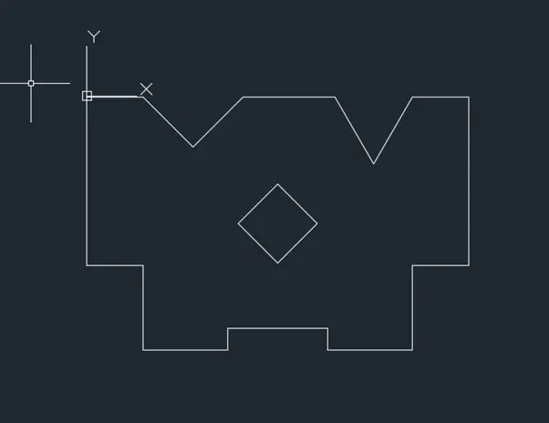
I. In command prompt type (startup:1)
II. Then file>new
III. Then create new drawing window select metric in default settings
IV. In advanced setup in units check on the architectural, angle in degrees, then ok
V. In command prompt type (L) where line command is woken
VI. In command prompt type (specify first point: 0’,0’)
VII. Switch on the polar tracking of 45,90,135
VIII. Now from start point place cursor at 0-degree tracking and type 3’enter in command prompt
IX. Next place cursor at 315-degree tracking and type 3’-91/4’’ enter in command prompt
X. Next place cursor at 45-degree tracking and type 3’-91/4’’ enter in command prompt
XI. Next place cursor at 0-degree tracking and type 4’-103/8’’ enter in command prompt
XII. Switch polar tracking 30,60,90
XIII. Next place cursor at 330-degree tracking and type 4’-15/8’’ enter in command prompt
XIV. Next place cursor at 60-degree tracking and type 4’-15/8’’ enter in command prompt
XV. Next place cursor at 0-degree tracking and type 3’ enter in command prompt
XVI. Next place cursor at 270-degree tracking and type 6’-9’’ enter in command prompt
XVII. Next place cursor at 180-degree tracking and type 3’ enter in command prompt
XVIII. Next place cursor at 270-degree tracking and type 4’-6’’ enter in command prompt
XIX. Next place cursor at 180-degree tracking and type 4’-6’’ enter in command prompt
XX. Next place cursor at 90-degree tracking and type 1’-2’’ enter in command prompt
XXI. Next place cursor at 180-degree tracking and type 5’-4’’ enter in command prompt
XXII. Next place cursor at 270-degree tracking and type 1’-2’’ enter in command prompt
XXIII. Next place cursor at 180-degree tracking and type 4’-6’’ enter in command prompt
XXIV. Next place cursor at 90-degree tracking and type 4’-6’’ enter in command prompt
XXV. Next place cursor at 180-degree tracking and type 3’ enter in command prompt
XXVI. and type C enter in command prompt
XXVII. In command prompt type (rec) where rectangle command is woken
XXVIII. In command prompt type (specify first point: 0, 0)
XXIX. in command prompt type (next point: 3,3)
XXX. Enter
XXXI. In command prompt type (ro:45) rotate whole rectangle by 45 degree
XXXII. Select the rectangle and move to 10’2”,6’9” as its geometric centre as the base point
XXXIII. enter
Result:
Given drawing was drawn in AutoCAD