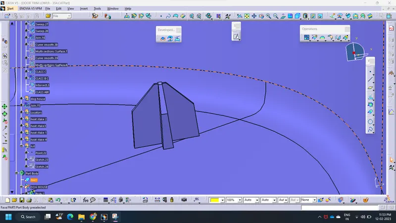
Door Trim Lower with Engineering Features
Door trim lower component through the given Class-A surface.
Tooling Axis creation:
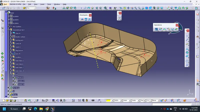
It is defined as the direction in which the mould/core and cavity open. Selection of the direction of the tooling axis depends on the ease at which components can be easily ejected.
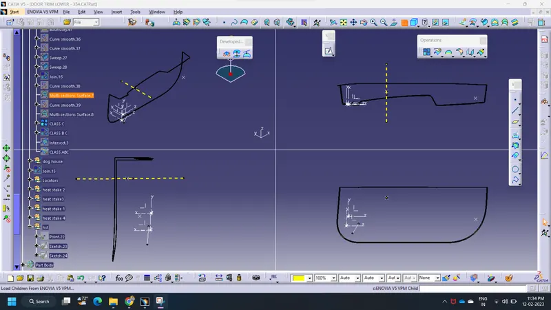
By analysing the component the most easily ejectable direction is somewhere close to the Z direction,(might be inclined to it) so we have made a sketch on the YZ plane of Axis System) to create a bisecting line considering the 2 faces which might be difficult to be tooled.
Draft Analysis of Solid Model
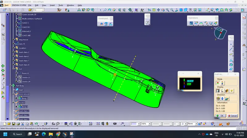
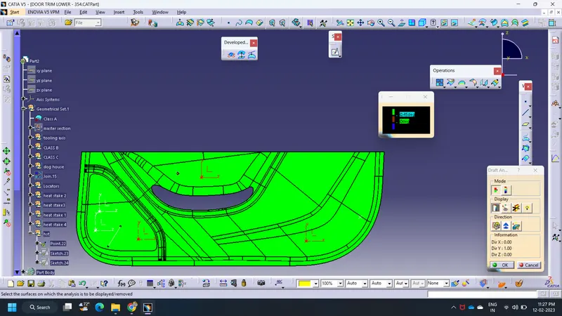
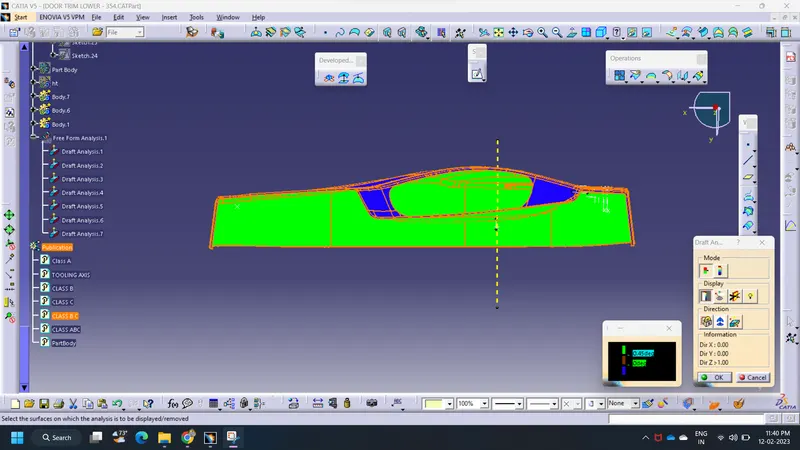
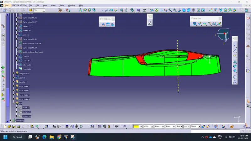
As we know minimum draft angle for the faces of the plastic component should be 3 degrees. So the value of 2.9 degrees (considering tolerance) is provided in the Draft analysis colour mode window Inside the colour scale, the GREEN bar shows the draft angle of 2.9 or above 2.9 degrees. The blue bar shows below 2.9 degrees draft angle the other limit being and the RED bar shows the negative draft angle. As shown in the image below all the top faces and side faces of the component are green, while the bottom faces are red. The line of demarcation between the green and red faces is the parting line which divides the core and cavity halves. The solid model has cleared the draft analysis successfully as shown in the image below.
CLASS -A
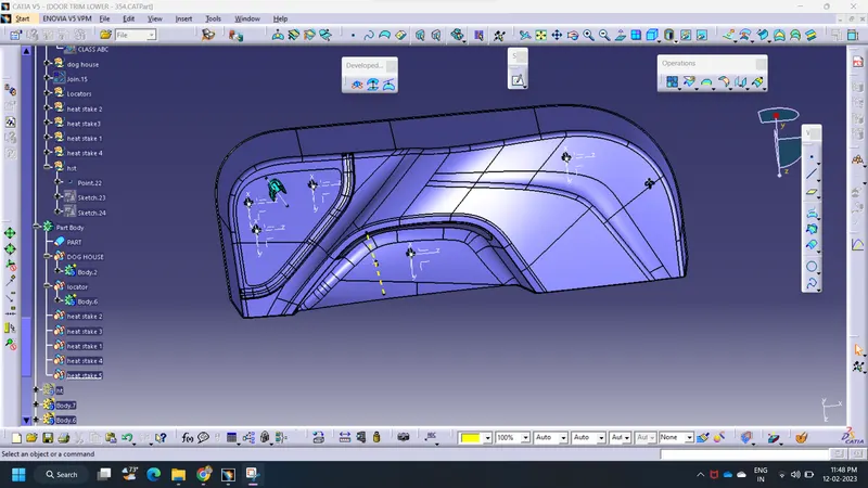
Class A surface are primary used in the automotive environment and rrefer to these surfaces
which are visible to outside world or to the humans..Class A surfaces are those surfaces ,which are vivible to us (interior/exterior) and have an shape and high surface quality.
DRAFT ANAYSIS CLASS - A
CLASS -B
class B are secondary surfaces that goes fee sometimes ,but are less impoortant sucha s the
inside of your glovebox,ash tray etc., these must be smooth and as well ,but aare not held to the standard thst class A surface.
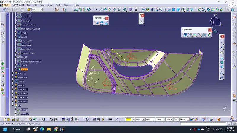
DRAFT ANALYSIS CLASS -B
CLASS - C
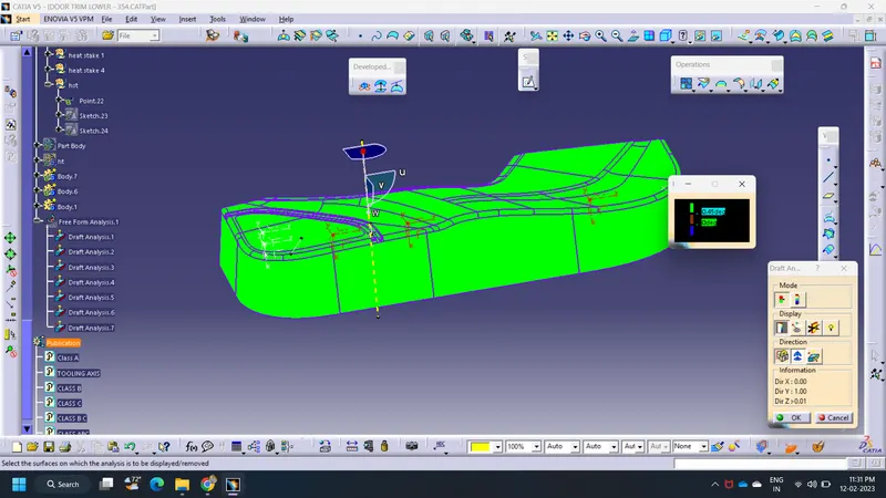
class C surface is the thickness between the class A and class B ,so there is no need of high end
finishing in class c surfaces.
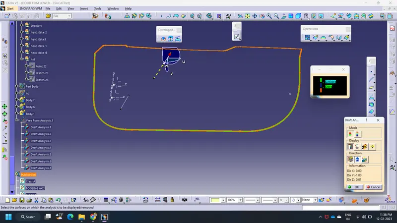
DRAFT ANALYSIS CLASS -C
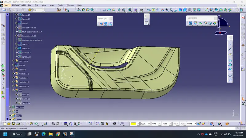
CLASS - BC
DRAFT ANALYSIS CLASS - BC
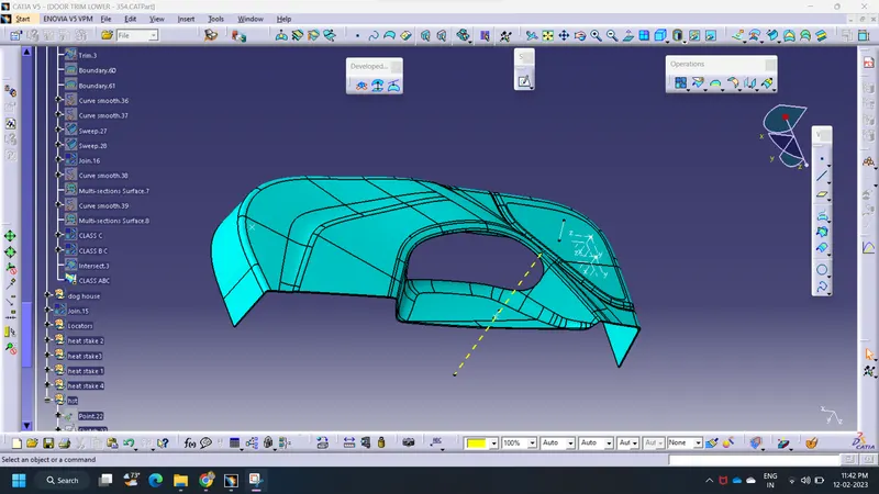
CLASS -ABC
Creation of ABC
- Click on insert geometrical set AC under input and then click on ok
- Define the ABC
- Join everything(class A,class C,class B) using join command.
- Publish ABC.
DRAFT ANALYSIS CLASS -ABC
CREATING THE DOGHOUSE
The dog house is an engineering feature used in the plastic trim design. Dog houses are used as a supporting feature. Sometimes other engineering features like snaps; locators, etc. are mounded on them to increase their strength.
The doghouse is created by following the design rules.
The nominal wall thickness guide range is from 0.75 mm to 3 mm for reinforced materials and 0.5 mm to 5 mm for unreinforced materials.
Related Courses
WALL THICKNESS (W) = 0.70 (NOMINAL THICKNESS OF PLASTIC MATERIAL)
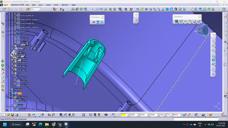
This process is usually done by Thicken surface command.The fillets and the draft are given as per the design rules.An important thing while designing a doghouse is to maintain 40% less thickness than the wall thickness (T) at the area of the intersection to avoid sink marks. So, a C shape is formed at the intersection.This can be made using the split command to remove the solid at the intersection
HEAT STAKES
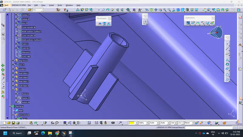
These heat stakes will enter the mating component and using a heat staking machine these heat stakes are melted and cooled. When cooled this will get hardened and the two components will stick together. Thus all degrees of freedom are arrested.Then, the ribs are created by following the rib design rules.The draft is applied to the sides of the ribs. As per the design rule, the ideal draft angle is 0.5 deg.
LOCATOR