Attachment Feature Creation (Ribs & Screw Boss)
1.Class A:
Class A surface are primary used in the automotive environment and rrefer to these surfaceswhich are visible to outside world or to the humans..Class A surfaces are those surfaces ,whichare vivible to us (interior/exterior) and have an shape and high surface quality.
2.Class B:
class B are secondary surfaces that goes fee sometimes ,but are less impoortant sucha s theinside of your glovebox,ash tray etc., these must be smooth and as well ,but aare not held to thestandard thst class A surface.
3.Class C:
class C surface is the thickness between the class A and class B ,so there is no need of high endfinishing in class c surfaces.
Steps in creating class A ,class B, Class c surfaces:
Step1:
Creating Tooling axis.
- Go to insert and select Geometrical set parent and then define the tooling axis.
- create a point with the help of point command.
- Create a line and make it as axis and chose the direction of the axis as Y -axis.
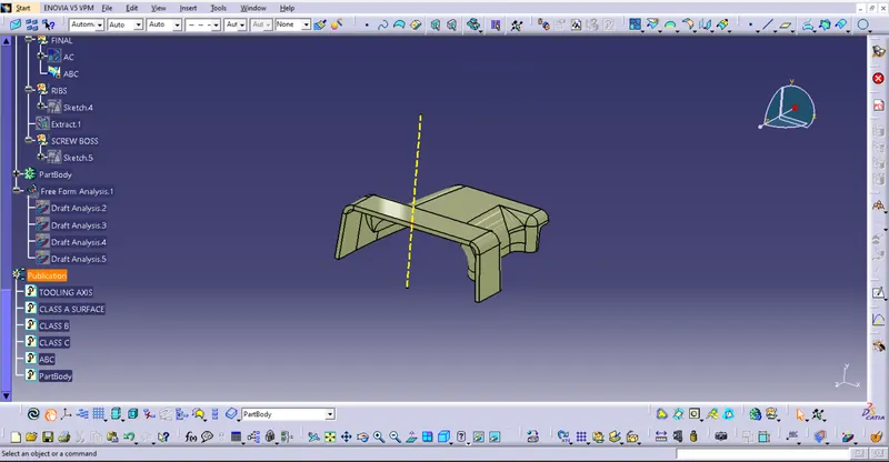
Step2:
Perform the draft analysis -1 :
- Change the mode of view into materialistic mode Go to insert - click on analysis - feaured draftanalysis.
- Drag the mini robot(direciton axis system) on to the axsis that we created.
- Click direction symbol and adjust the mini robot on the same axis.
- Lock the direction with the help of lock command.
- Click on the surface which need to be done draft analysis.
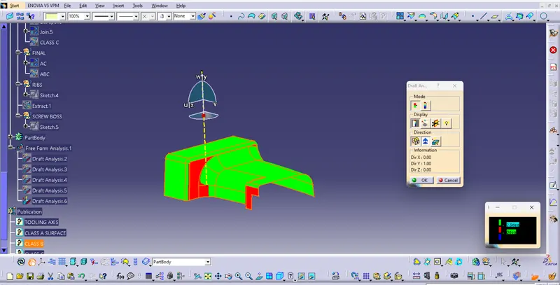
Step3:
Publication
- Select the CLass A surface - Tooling Axis -click on publication click on yes ,and click on ok.
Step4:
Creation of Class B surface
- Insert Geometrical set(class B) under Geometrical set-1 define Class B with the help of the following commands done the class B
- Select the Class A surface and perform an offset of 2.5 mm.
- Fill the space with the help of Multi Scectional Surface command.
- Now, Join the Offset and Multi Scectional Surface by the use of JOIN command.
- Publish Class B.
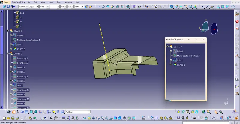
Step5:
Creation of Class C
- Insert geometrical set under(Geometric Set 1) and click on ok.
- Define class C,click onboundary condition select the boundary and select limit 1 and limit 2 click on ok.
- Click on sweep surface and sweep the boundary.
- Repeat the same curve on all surfaces.
- Join all the surfaces.
- Extrapolate the unjoined surfaces and trim them.
- After joining Publish Class C.
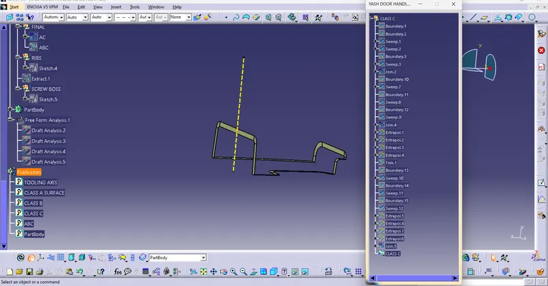
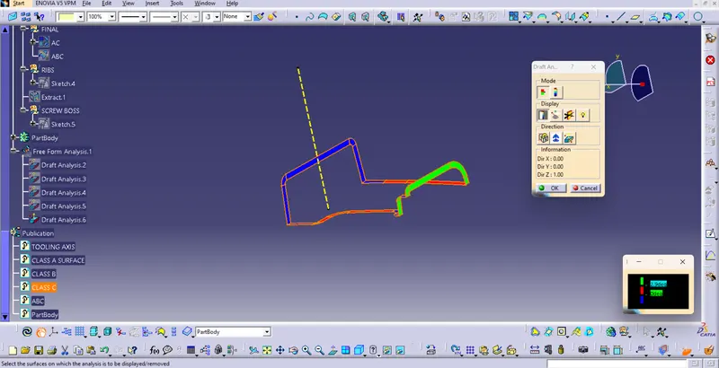
Step 6:
Creation of ABC
- Click on insert geometrical set AC under input and then click on ok
- Define the ABC
- Join everything(class A,class C,class B) using join command.
- Publish ABC.
Step7:
Perform the draft analysis -2 :
- Change the mode of view into materialistic mode Go to insert - click on analysis - feaured draft
analysis. - Drag the mini robot(direciton axis system) on to the axsis that we created.
- Click direction symbol and adjust the mini robot on the same axis.
- Lock the direction with the help of lock command.
- Click on the surface which need to be done draft analysis.
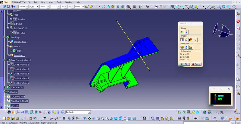
Step 8:
Creation of Close surface:
- Go to Mechanical Design - Part Body.
- Define Part Body and then Select the ABC Body and Click on CLOSE SURFACE command.
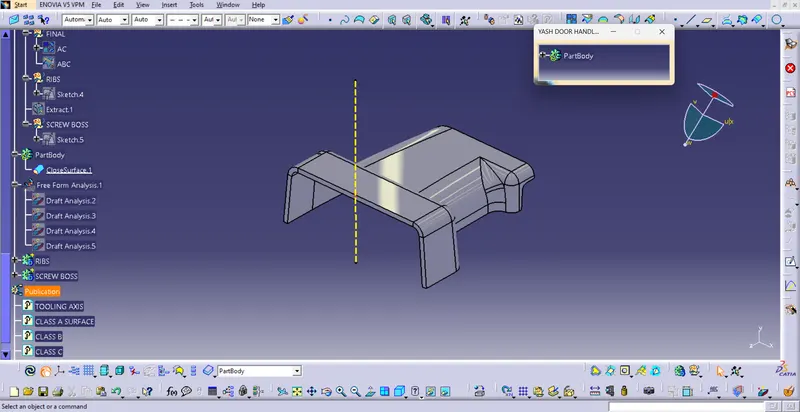
Step 9:
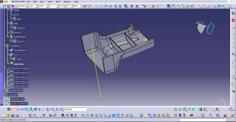
Creation of Ribs:
- Insert Geometric set(Ribs) under Geometric set 1.
- Sketch two lines.
- Create a body(Ribs) under Part Body.
- Pad The Lines of thick profile and thin pad of neutral fiber.
- Draft the pad with 0.5deg angle with the pulling direction of the tooling axis.
- select the union trim and Trim the ribs with part body.
- Apply the edge fiilets to the ribs with radius 0.25 mm.
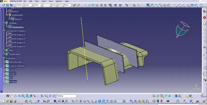
Step 10:
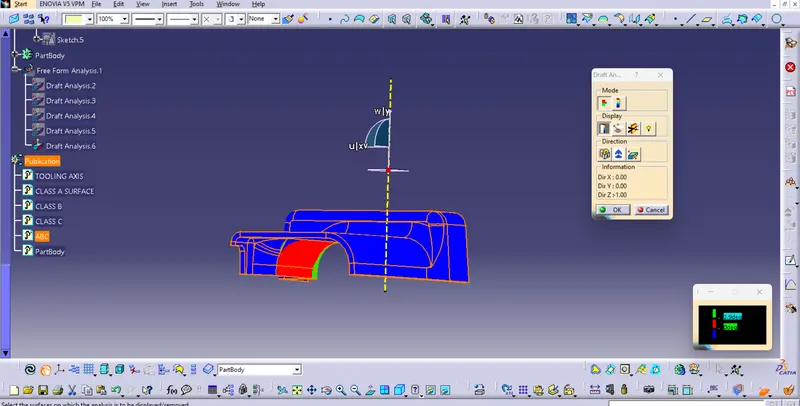
Perform the draft analysis -3 :
- Change the mode of view into materialistic mode Go to insert - click on analysis - feaured draft
analysis. - Drag the mini robot(direciton axis system) on to the axsis that we created.
- Click direction symbol and adjust the mini robot on the same axis.
- Lock the direction with the help of lock command.
- Click on the surface which need to be done draft analysis.
Step 11:
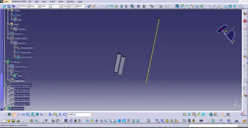
Creation of Screw Boss:
- Insert Geometric set(Screw Boss) under Geometric set 1.
- Sketch two circles.
- Create a body(Screw Boss) under Part Body.
- Pad The Circles
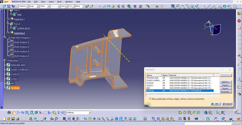
- Draft the pad with 0.5deg angle with the pulling direction of the tooling axis.
- Select the Union trim command and trim the screw bosses with part body.
- Apply the edge fiilets to the Screw Bosses with radius 0.25 mm.
Step 12:
Perform the draft analysis -4 :
- Change the mode of view into materialistic mode Go to insert - click on analysis - feaured draft
analysis. - Drag the mini robot(direciton axis system) on to the axsis that we created.
- Click direction symbol and adjust the mini robot on the same axis.
- Lock the direction with the help of lock command.
- Click on the surface which need to be done draft analysis.
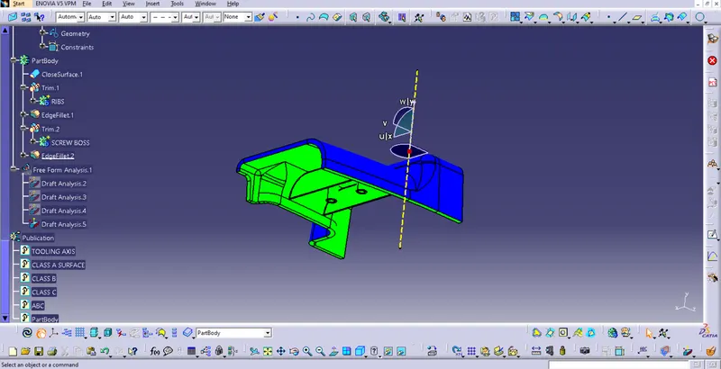
Step 13:
Publishing of Part body: