Door Trim Lower with Engineering Features
Methodology opted for Attachment Feature Creation (Ribs & Screw Boss) :
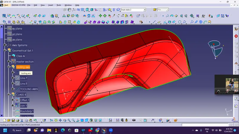
STEP 1: CREATION OF TOOLING AXIS:
Create a tooling axis on a given model (base bracket) by selecting convienient to the drafting analysis'
- click on point
- select the surface one dialoge box wll appear select surface and click on ok.
- click on line and select point-direction in dialog box and click on point and click on ok.
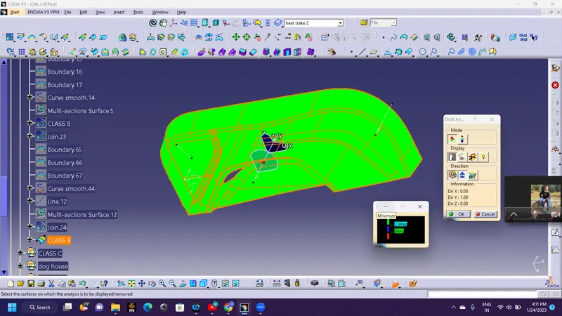
STEP 2: DRAFTING ANALYSIS ON CLASS-A SURFACE:
- click on insert---analysis---FEATURE DRAFT ANALYSIS
- Drag the compass to the tooling axis
- click on compass in the dialog box---drag some distance---lock it---select the surface with respect to the tooling axis.
- If the entire surface is appear in green in clour the drafting analysis is correct if not make corrections according to it.
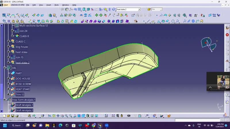
STEP 3: CREATION OF CLASS-B SURFACE:
- click on extract command click on surface and click on ok.
- click on untrim command and click on surface and click on ok.
- click on extrapolate command and click on surface and click on ok.
- click on off-set command and click on surface give a value of 2.5mm and click on ok.
- click on multi body projection--click on edges of surface and select one guide curve and click on ok.
- click on trim command to trim the exta surface acording to the need.
- click on edge fillet command and give the fillet value of 3mm and 1 mm at the edges.
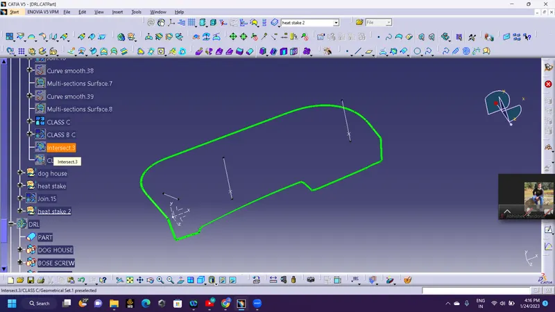
STEP 4: CREATION OF CLASS-C SURFACE:
- click on boundary command and click in edge of the surface and give the limit and click on ok.
- click on draft command and give the draft angle and give the value of 2.9 and click on ok.
- click on extrapolate command and click on surface and click on ok.
- click on trim command to trim the exta surface acording to the need.
STEP 5: CREATION OF CLASS-A,B,C SURFACE:
- Click on jion command to join all the surfaces to make it as acomplete surface model.
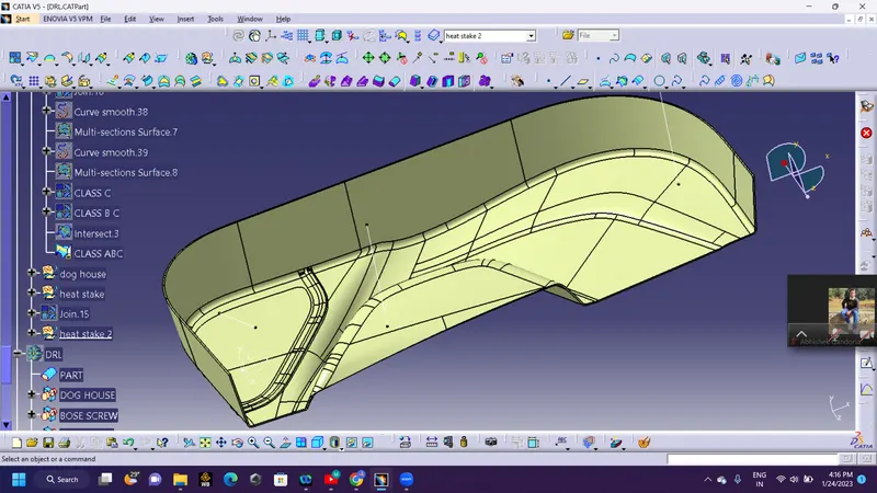
STEP 6: CREATION OF SOLID:
- Click on start, click on mechanical desigan--part design'
- click on part body, click on define part body, and click on fill surface and click on ok.
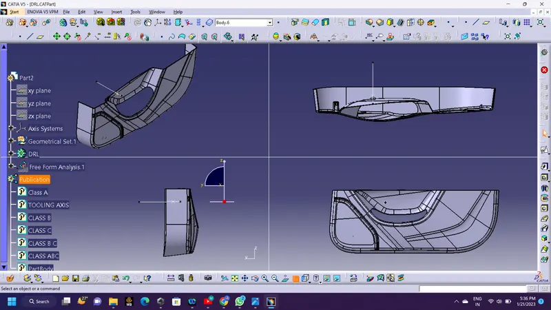
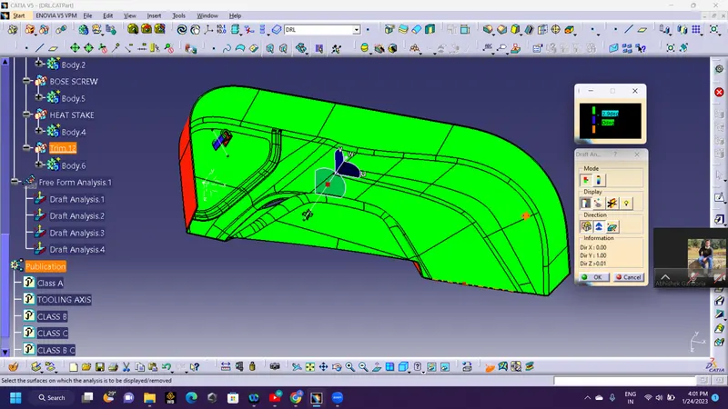
STEP 7: DRAFT ANALYSIS SOLID MODEL:
- click on insert---analysis---FEATURE DRAFT ANALYSIS
- Drag the compass to the tooling axis
- click on compass in the dialog box---drag some distance---lock it---select the surface with respect to the tooling axis.
- If the entire surface is appear in green in clour the drafting analysis is correct if not make corrections according to it.
Step 8: Creation of Dog House:
- Create a a rectangle and pad it
- use shell command to make it as a shell
- complete the dog house as per given dimensions in the question
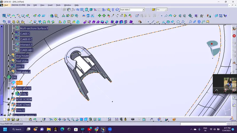
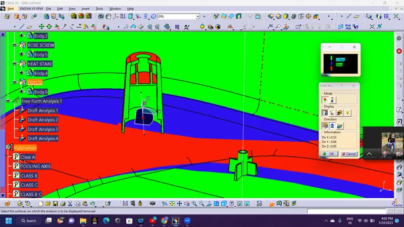
Step 9: Creation of heat stakes:
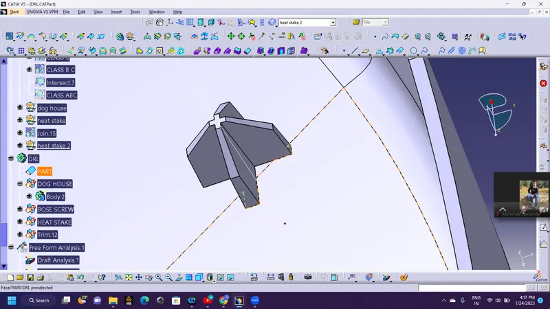
- click on line command--draw two lines by constraining with axis--click on ok.
- Insert part body--define the work object--click on rib command--and give the value of 2.5 thickness of surface and click on ok.
- Use boolean operations to add the ribs to the part body and change the add to uninon trim to remove extra faces and click on ok.
- click on chamfer command and give the value of 6mm and 5mm and click on ok.
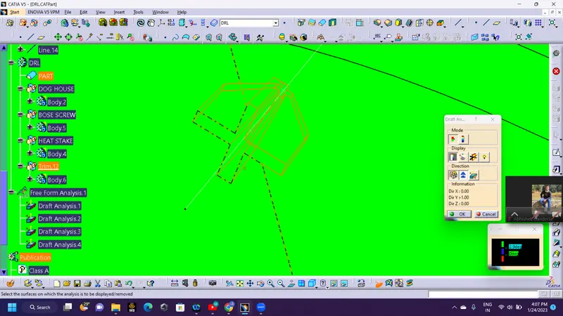
Step 10: Creation of Screw Boss:
- click on circle command--draw two circles by constraining with axis--click on ok.
- Insert part body--define the work object--click on pad command--and give the value of 5*thickness of surfaceand click on ok.
- Use boolean operations to add the circles(Bose Screws) to the part body and change the add to uninon trim to remove extra faces and click on ok.
- click on edge fillet command and give the value of 0.25 and click on ok.
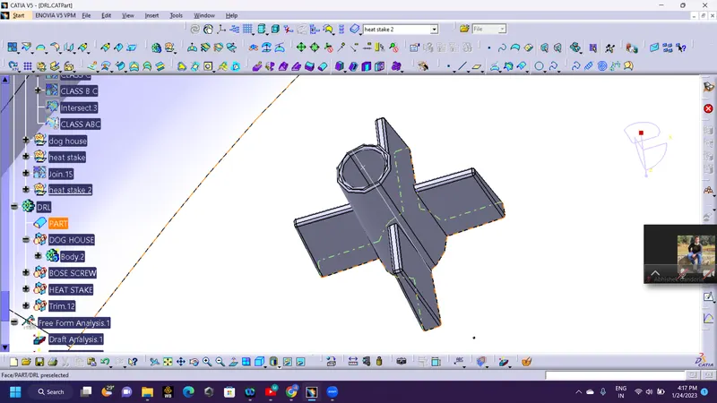
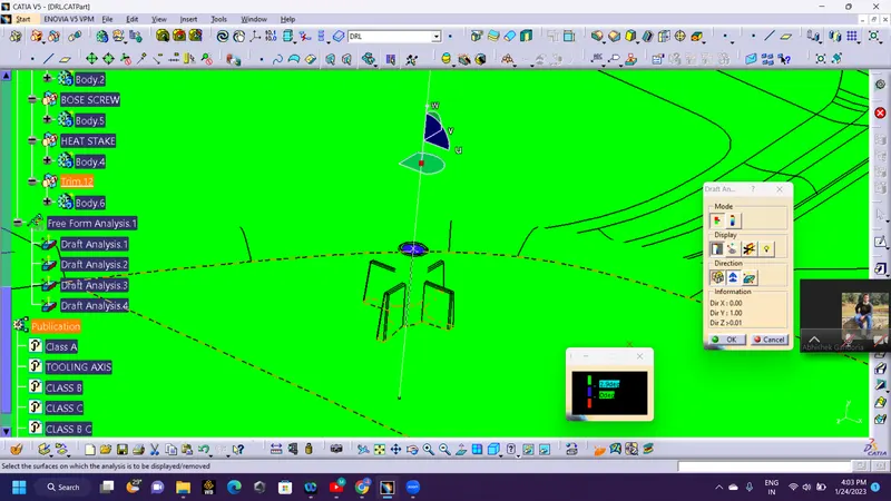
STEP 11: DRAFTING ANALYSIS ON SOLID SURFACE:
- click on insert---analysis---FEATURE DRAFT ANALYSIS
- Drag the compass to the tooling axis
- click on compass in the dialog box---drag some distance---lock it---select the surface with respect to the tooling axis.
- If the entire surface is appear in green in clour the drafting analysis is correct if not make corrections according to it.