DOOR TRIM LOWER WITH EGINEERING FEATURES
OBJECTIVE: To create the Door Trim Lower's Plastic Component using the Class A Surface that is provided. Desired Thickness of the Plastic Component is 2.5mm with 3.2 degrees as the Draft Angle.
REPORT:
Types of Surfaces and their importance for an Automotive Plastic Designer:
- Class A Surface: Class A is an aesthetic surface with the highest quality finish. Most Class A Surfaces for an Automotive Component are made using 'Autodesk-Alias' based on the final Concept-Sketch. All Class A surfaces should have 'Curvature-Continuity' which means the continuity between the surfaces should share the same boundary. It is taken as a reference by the Automotive Plastic Designer to create 'Class B' and 'Class C' Surfaces.
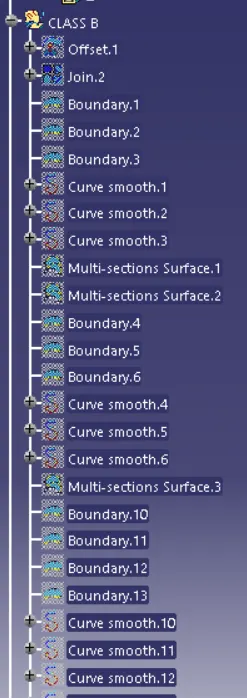
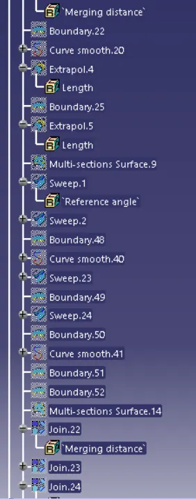
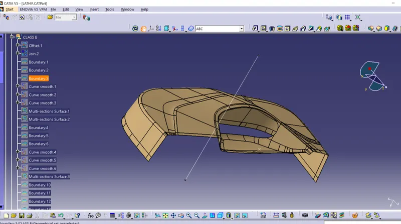
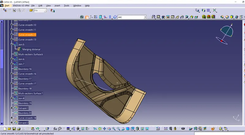
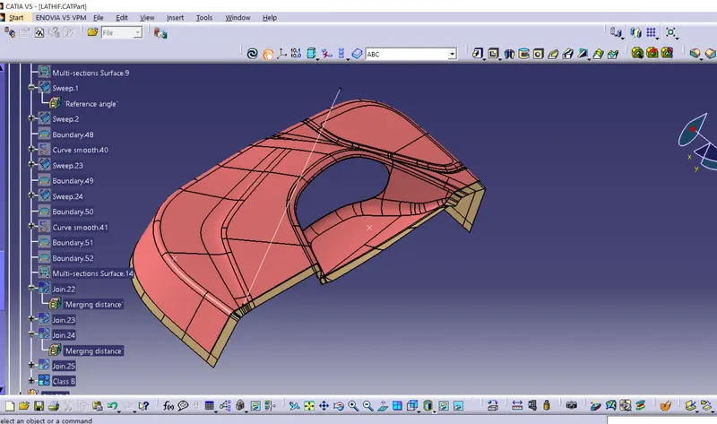
- Class B Surface: The Class B Surface resides below the Class A Surface at a certain thickness. It is created using Engineering Principles that consist of all the necessary features such as Ribs, Bosses, Snaps, etc. This surface isn't visible to the observer from the outside.
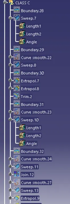
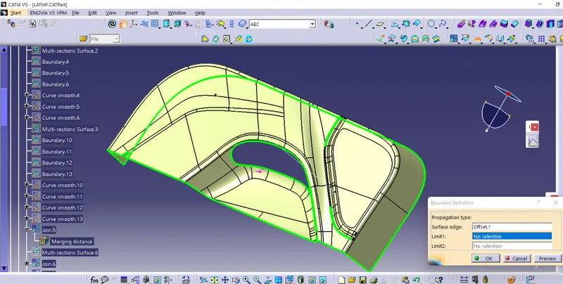
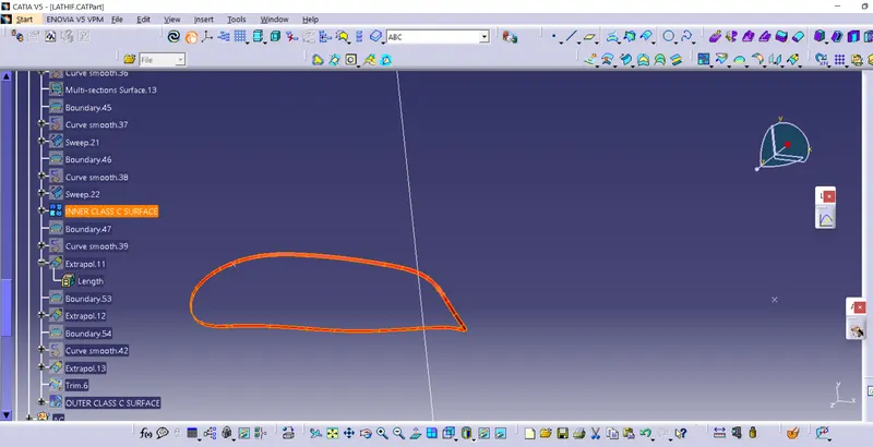
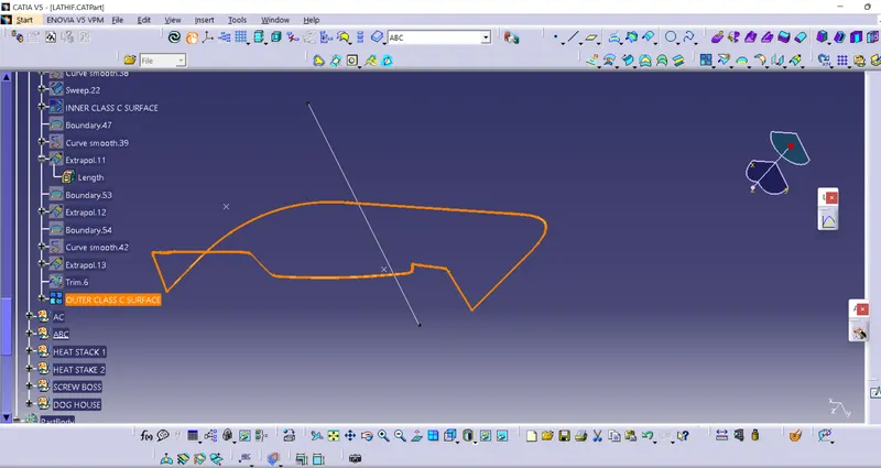
- Class C Surface: The Class C Surface is the surface created between the Class A and Class B surface to join them with each other.
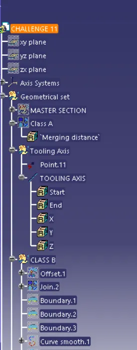
ree Structure
Class B
Class C
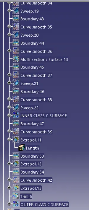
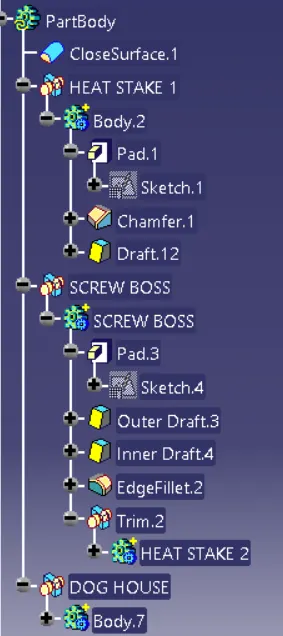
Part Body
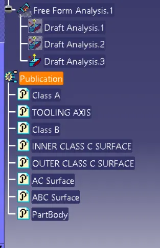
Analysis & Publications
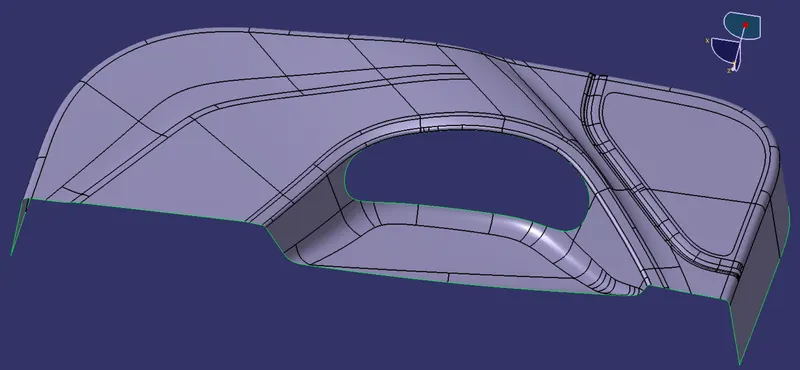
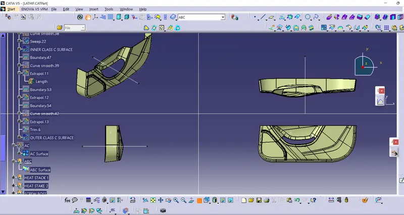
Our Class A Surface:
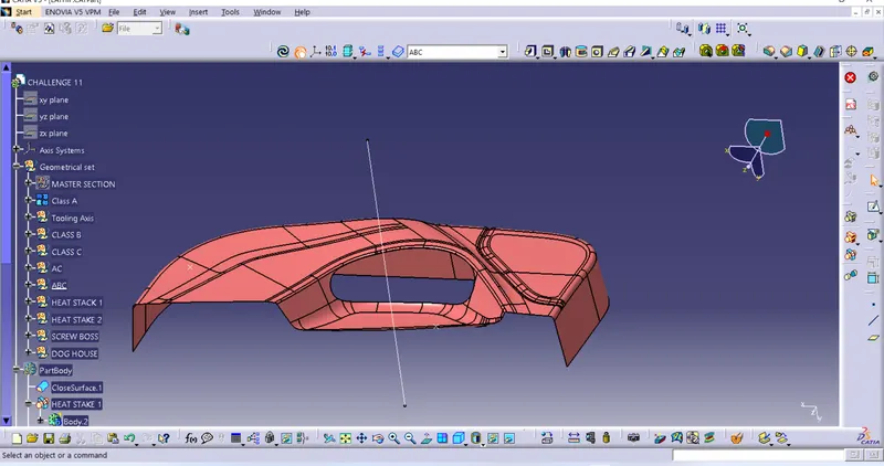
PROCEDURE TO CREATE THE MAIN TOOLING AXIS:
There are two different methods that we can use to create the Main Tooling Axis for our Class A Surface. When we're trying to create our Main Tooling Axis we always have to focus on the direction in which we're going to create the Main Tooling Axis.
- Using a Vertex to create a line along the axis which allows us to view all the holes & exposes the maximum surface area of the Class A Surface.
- Using Inertia Method to find out the Center of Gravity and create a line along it.
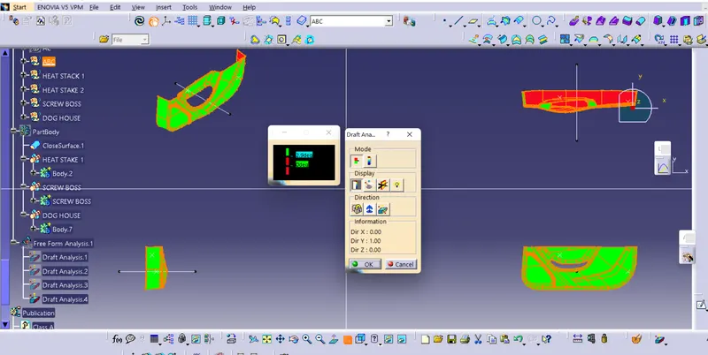
Draft Analysis on Class A Surface :
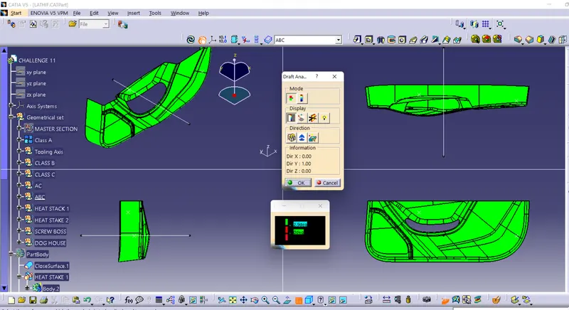
To start the Draft Analysis in the 'Generative Surface Design Workbench', we will go to 'Insert' and then look for the option called 'Analysis'. Once found, we will go under that and click on 'Feature Draft Analysis. This will open the 'Draft Analysis' Dialogue box. There, we will ensure that under 'Mode' we have selected 'Quick Analysis', under 'Display' we will select 'Show or Hide the Color Scale' and then select '3 Degrees' as the permissible draft angle. Then, under 'Direction' we will choose the icon with the symbol of the compass on it which stands for 'Use the Compass to define the new current draft direction'.
Class B Surface :
Class C Surface:
Draft Analysis on ABC Surface
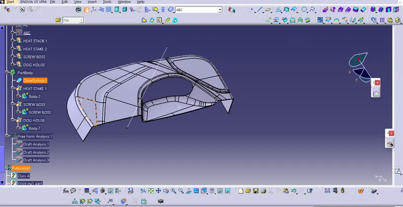
Close Surface
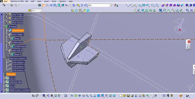
Master Section
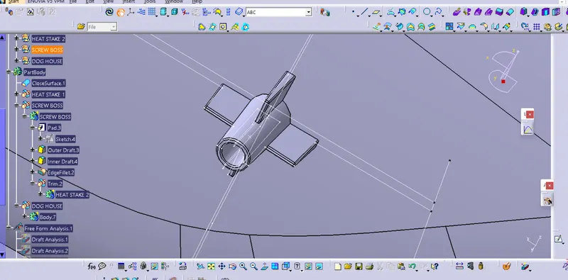
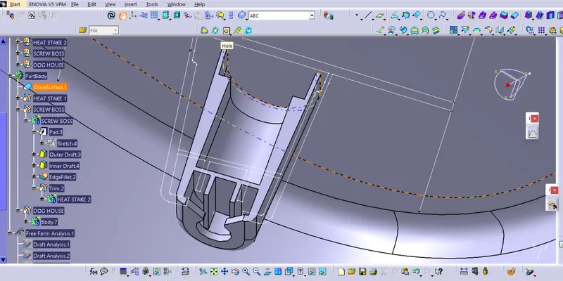
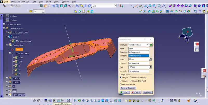
Creation of Tooling Axis:
- Create a point on surface A
- Create a line using the Line-Definition command while choosing point-direction as a line type.
- Select point and direction will be toward the Y component.
Draft Analysis:
The draft is the amount of taper for moulded or cast parts perpendicular to the parting line. Draft angles are a design consideration that makes it much easier for a part to release cleanly from a mould.
Procedure to Perform Draft Analysis:
- Click on the Draft Analysis under the Aanalysis Toolbar in the part workbench.
- Now drag the compass and place it on the Tooling Axis.
- Next Adjust the compass and lock it on the Tooling Axis.
- Select the Final Part in which the Draft Analysis should Perform
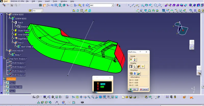
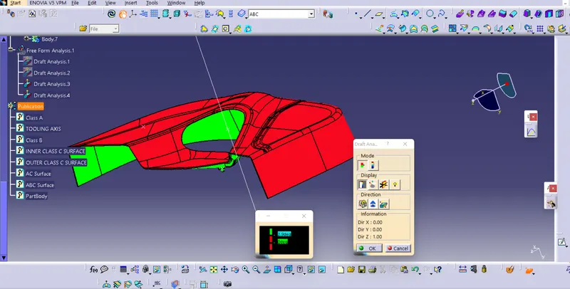
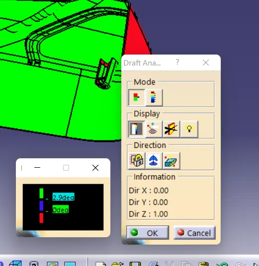
Green colour - Draft Angle is more than 2.9 degrees
Blue colour - Draft Angle is between 0-2.9 degrees
Red Colour - Draft Angle is less than 0
Conclusion:
Hence the solid body and Engineerin features of DOOR TRIM LOWER was created by using given Class A surface.