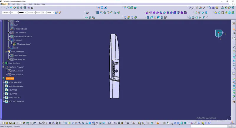
Door Arm Rest Week 8 Challenge
Aim:- Creation of Door Arm rest and add thickness to it.
Take the Thickness of the component to be 2.5 mm
In an automotive context, an armrest (or armrest) is a feature found in many modern vehicles on which occupants can rest their arms.
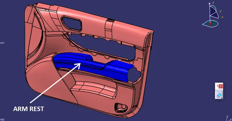
Tooling Axis:
- It is the direction in which the component will be ejecting after the molding process is completed.
- The direction of the tooling axis should clear the maximum portion of the part.
- It should be selected in such a way that number of side cores will be minimum as it will add more cost to the process.
Workbench and tools used:
Generative shape design
- Extract
- Extrapolate
- Join
- Trim
- Offset
- Boundary
- Edge fillet
- Intersection
- Sweep
- Close surface
- Feature Draft Analysis
Design Process in CATIA V5
Given Data,
Class A surface,
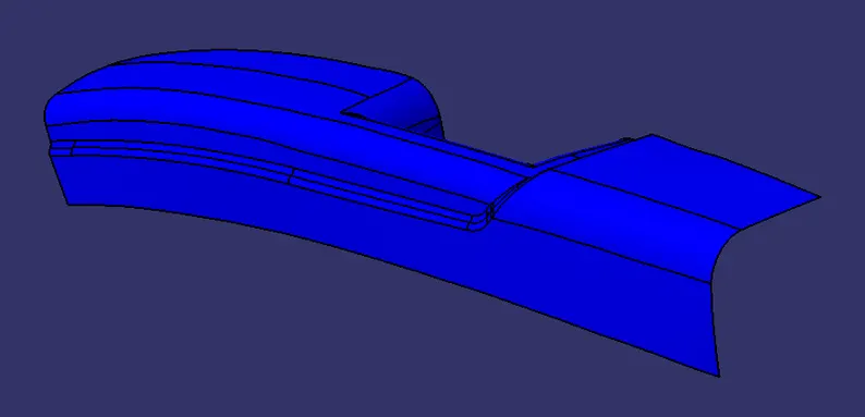
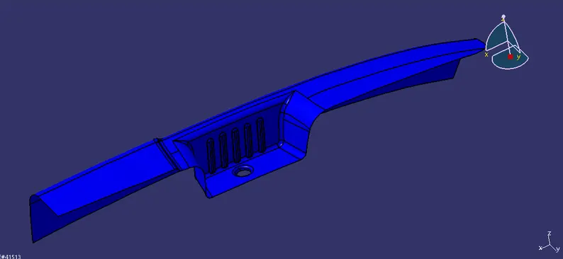
Now we will be doing Draft analysis on Class A Surface, for that, we need a tooling axis.
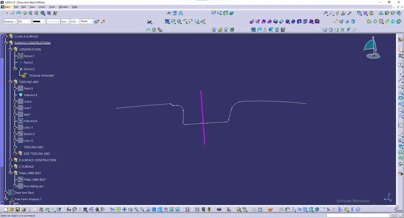
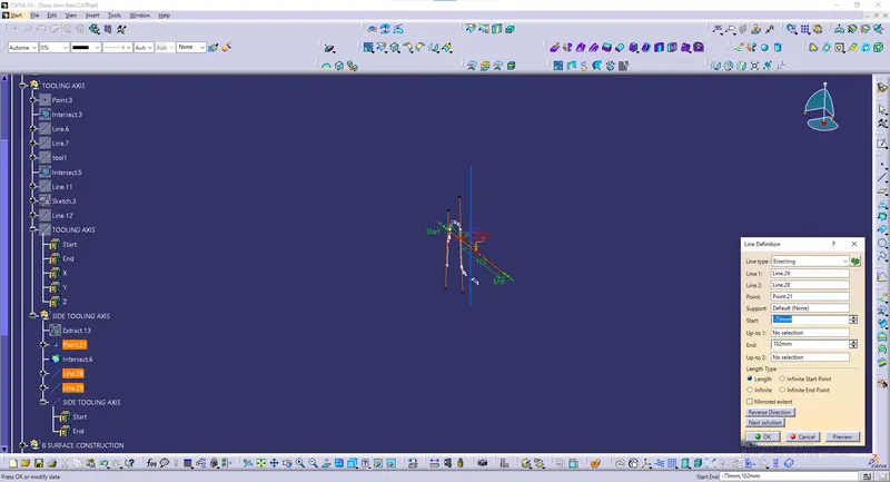
Tooling Axis creation: Bisecting Method
- First, we will extract the base surface of class A and on that create the point and then create the Axis system at that point.
- As we have only three sidewalls, we need to create a tooling axis with a different methods.
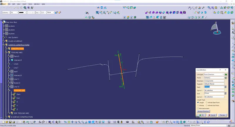
- Then creating intersection curves in the X direction and create sidelines on that curves and then create the bisecting line in sketcher.
- Then creating intersection curves in the Y direction and create sidelines on that curves and here we have only one side wall so we will create line passing through the point which we have created in above steps at an angle of draft in sketcher. Here angle taken is 5 degree to get all faces feasible with tooling direction.
- Then creating bisecting line through X and Y direction tooling lines.
- After that creating the dummy tooling axis in Z direction.
- This line is the Dummy tooling axis for our part.
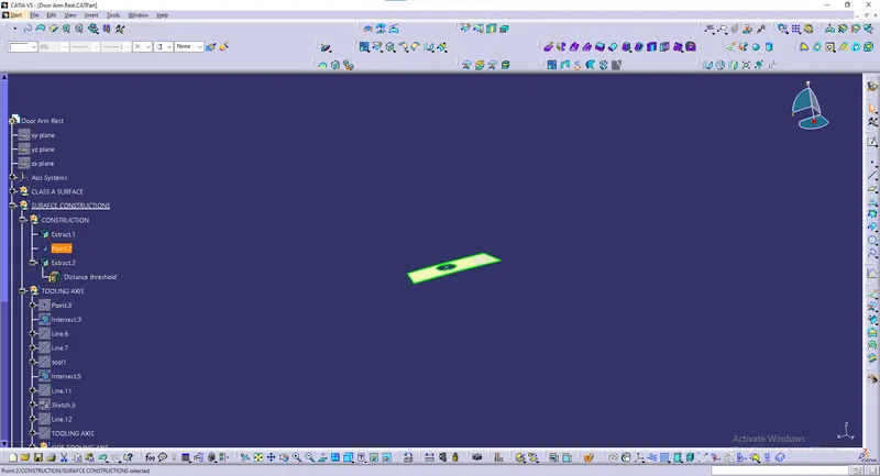
Compass method:
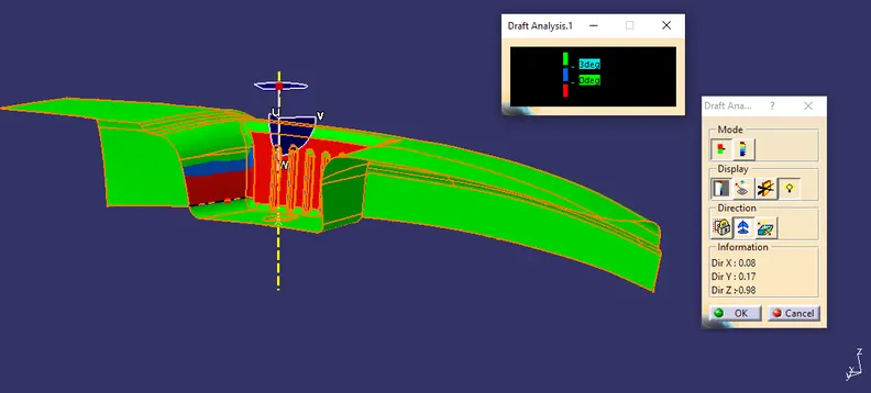
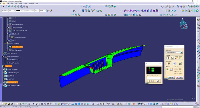
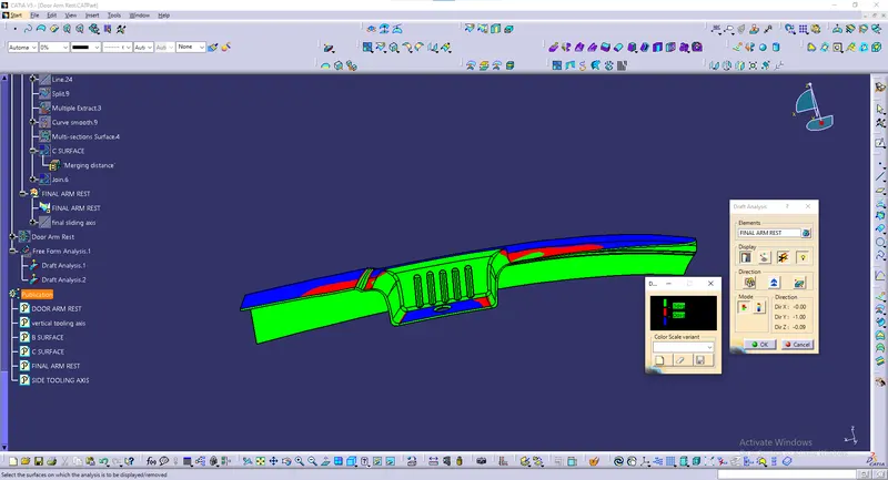
Checking draft analysis with dummy tooling axis and if tooling axis is not correct then adjusting compass to get the surfaces as green.
Then right click - lock current orientation - cancel draft analysis - select line - line direction - compass direction.
Then view - reset compass
This line will be main tooling axis
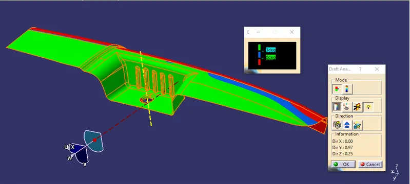
Creating different tooling axis for cavity and adjusting with compass then creating line with compass direction in Y - direction which is for slider.
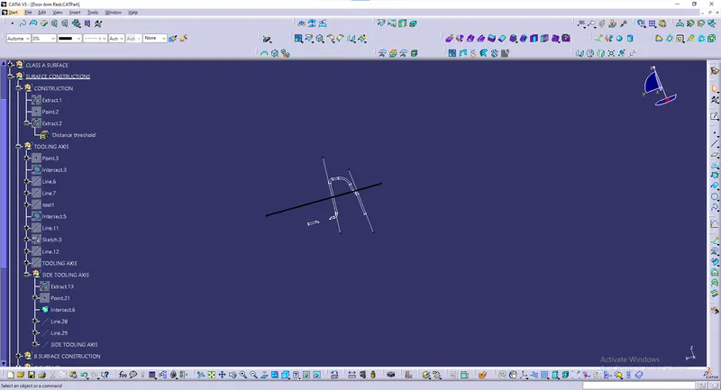
Tooling Axis for side core
Create the line in X-direction for side cores.
B- surface creation:
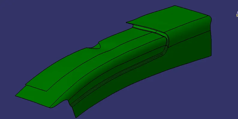
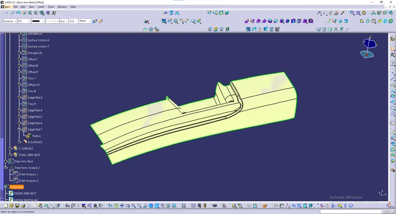
- Extract class A surface.
- Untrim extracted surfaces.
- Extrapolate to some extend.
- Use trim and select proper surface.
- Offset inward at 2.5mm
- Use edge fillet.
C - surface creation:
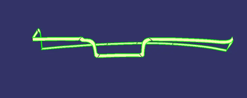
- Take outer boundary using Boundary command of class A surface
- Use smooth curve.
- Use sweep command to create surface using tooling axis and draft angle as 3 degree.
- Create points and line to split the surfaces as and where ever needed.
- Join the split surfaces with multi section surface.
Final Body creation:
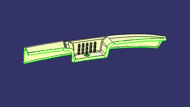
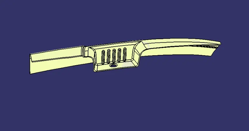
- Join class A surface and c surface
- Trim resulting surface with B surface
- Join the surface
- Result is complete close surface.
Draft Analysis:
- 1st to check the connectivity of the class A surface.
- Ensure that there is no gap between the component using join command.
- We can visually check it or by clicking boundary command.
- After that disassembled.
Solid body:
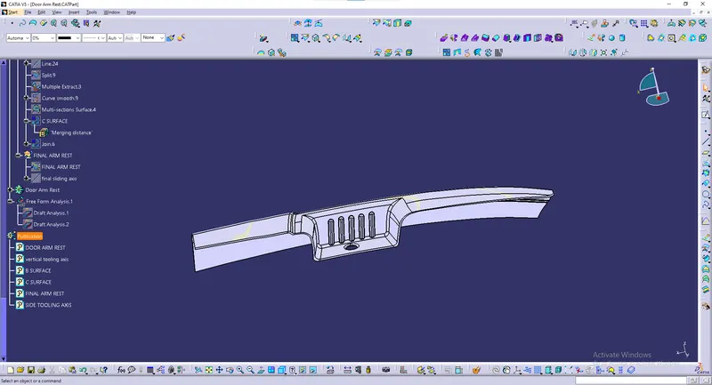
- Change to part workbench
- Create body
- Surface Base feature - Close surface - select last join.
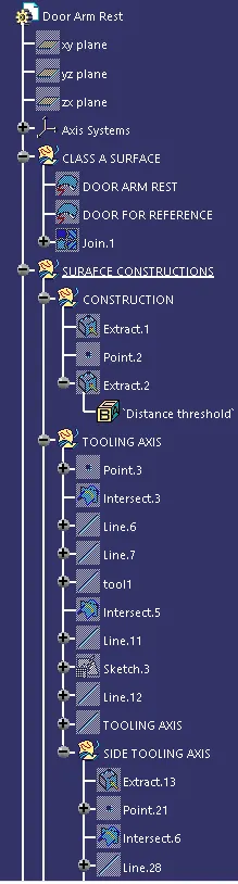
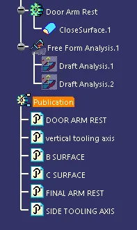
Tree structure:
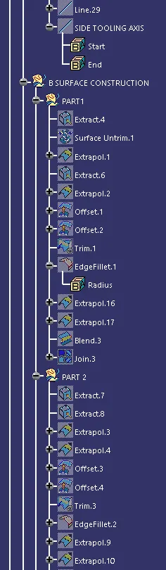
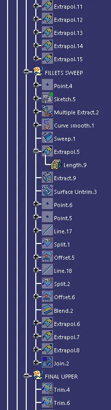
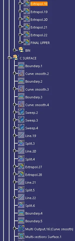
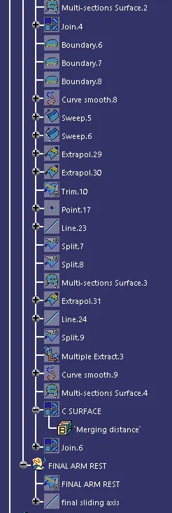
DOOR ARM REST VIEWS:
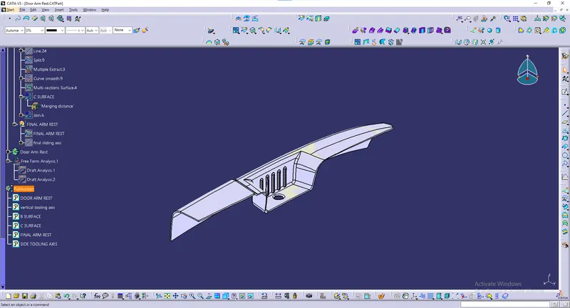
Isometric view:
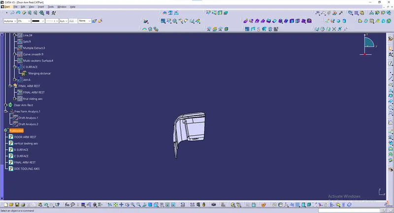
Front view:
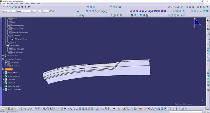
Side view:
Top view: