Door Arm Rest Week 8 Challenge
Aim:
With the given door arm rest create tooling axis and Class B and C surface and perform draft analysis.
Procedure:
Creation of Tooling Axis
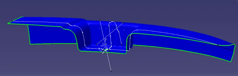
For creating the tooling axis create the point at the centre by extracting the base part and provide a point at it. After that create an line with the point insert an axis and with the axis create intersection on the A surface provided.
With the intersection point draw the line and take bisect that makes tooling axis. And for slider axis intersection is made on the other side as the image. Draw the line.
Creating of B surface
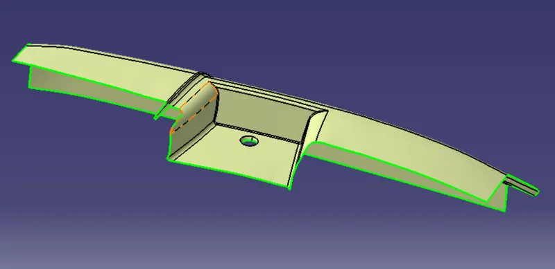
The above flange part is extracted , untrimed and extrapolated. After this things are done the extra parts are removed with the trim option. After that fillet is given on the both upper part.
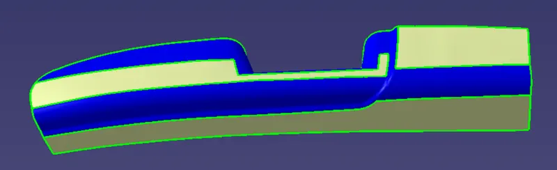
The below fillet part a point is made on the centre of the curve. With the point clicking on the one curve and with the centre point on the point definition dialogue box a point creates on the centre automatically.
After that using the multiple extract select the line as the image below. Select the sweep option and create a surface with help of the line. After tha extrapolate it.
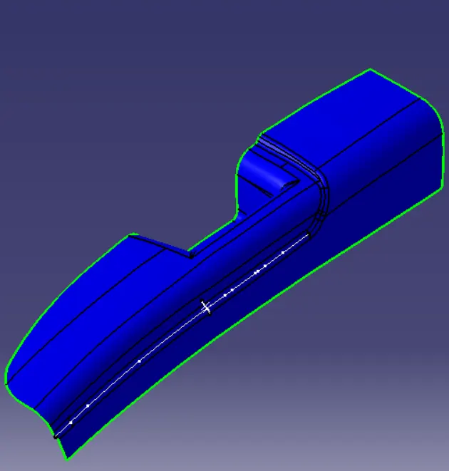
After the sweep operation select another surface extract it. Do untrim and extrapolate it. After that the surface created at the sweep and the surface created now has to be trimmed together.
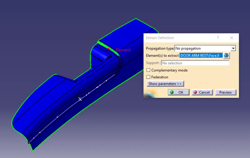
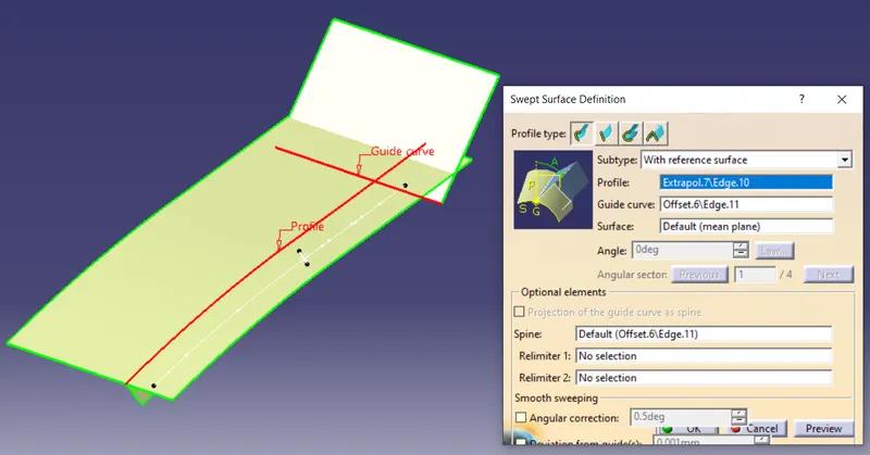
After trimming the surface we get a surface like in a shape of L. We want another surface so that we can perform the fillet. For that using the sweep operation with the subtype as with reference surface select the lines as in the image.
There creates another surface connecting the two surfaces.
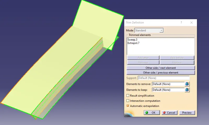
Now to remove the left side part trim is performed. After that we dont need the upper surface for that using the multiple extract the two line is selected as the image below.
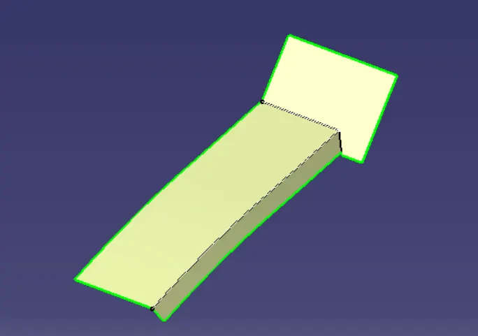
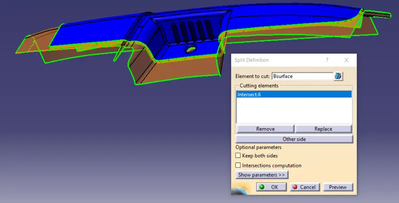
With the split option the upper surface is splited with the extracted created.
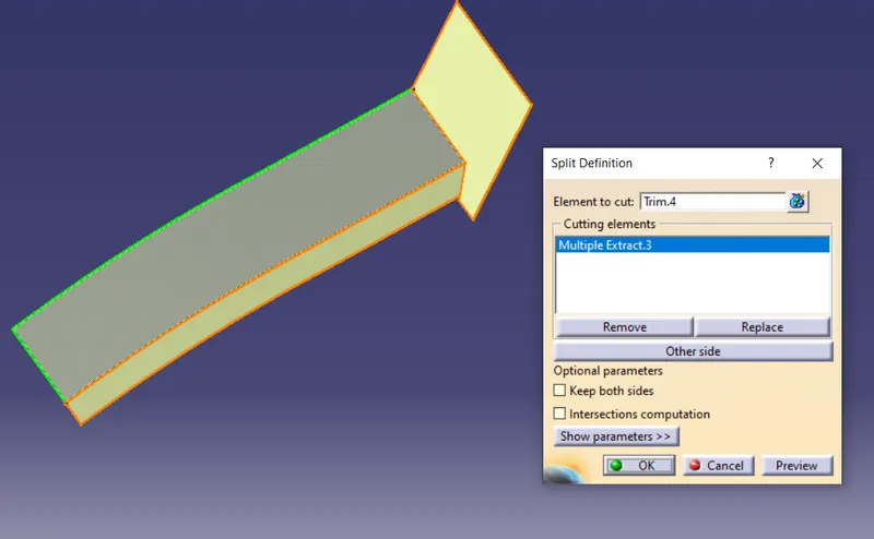
After that the flange which is created at the started is brought together with this part. It is also trimmed with the repect to the part created now. The same thing is performed in back side too.
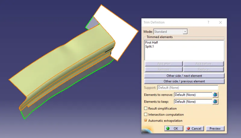
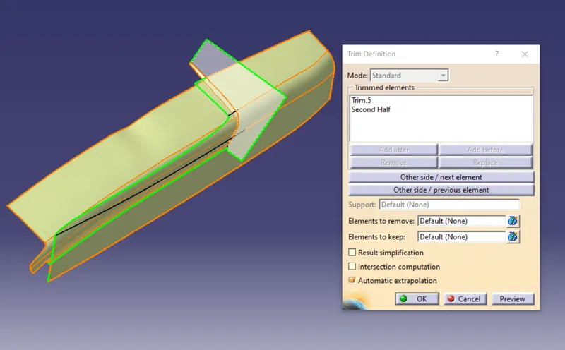
After performing the trim option the part looks like this.
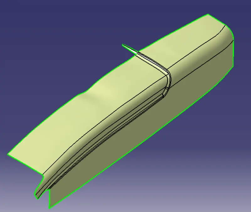
Now the base part. It is extracted and utrimmed and extrapolated. After extrapolation it is made offset. And this base part is attached with the part created now with the trim option. After that perform the fillet.
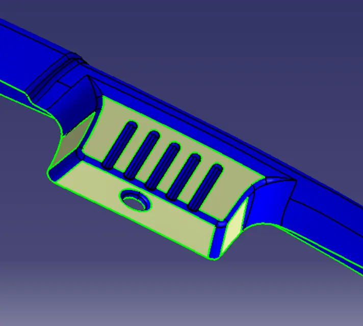
Each fillet has different values so extract the fillet region from class A surface and untrim and measure it and use the value according to the fillet whether it has to be added or subracted.
Creation of C surface
After the creation of B surface we need to create the C surface. For that select the boundary and use the limit 1 and limit 2 option. Limit 1 and 2 are used because it is created point by point.
Creation of intersection by hole and using the sweep option creates problem. For that it is selected separately and sweep it for the surface creation.
Now joining the Class A and C surface together. After that with the intersection option create and intersection on the joined surface. With the help of the intersection joint split the Class B surface.

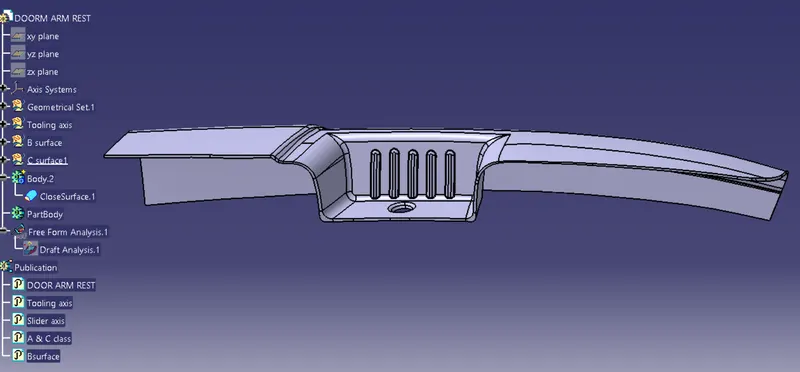
The final image after change it into closed surface.
Conclusion:
Draft Analysis
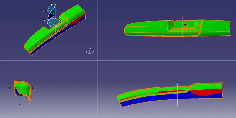
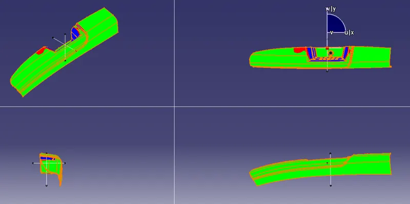
The door arm rest is performed with the draft analysis with the tooling axis and slider axis which is created. With the analysis with the part is failed to clear is some area so it cannot be taken to perform further operation.
Result:
For the door arm rest created tooling axis and Class B and C surface. After the extraction using the thickness and offset the surface with out fail. During the draft analysis the part has not cleared and failed for futher process.