Door Arm Rest Week 8 Challenge
AIM
To Create the door arm rest by using catia v5.
SOFTWARE USED
CATIA V5
DRAFT ANLAYSIS
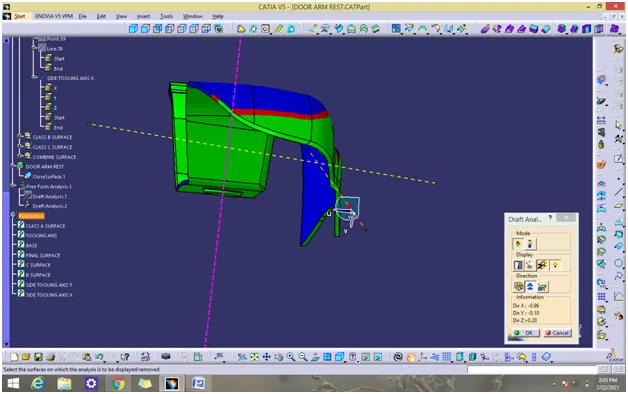
Draft analysis in catia is a command that is used to detect if the part you drafted will be easily removed from the mold. it is performed based on color ranges identifying zones on the analyzed element.
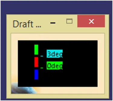
Most of the industries is using minimum draft angle is 3 degree
PROCEDURE
- Check all the boundary whether it has connected or not.
- Check the model visually & choose the best tooling direction which should be easy for draft.
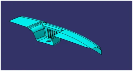
- After analyzing the above model, there is an chance for undercut when we consider tooling axis from z.so we have to create tooling axis on x,y and also z
CREATING THE TOOLING AXIS
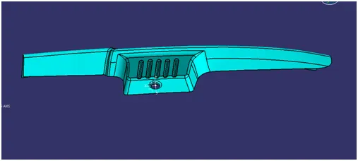
- Create a point 1 and insert a axis system on the point 1 as shown below
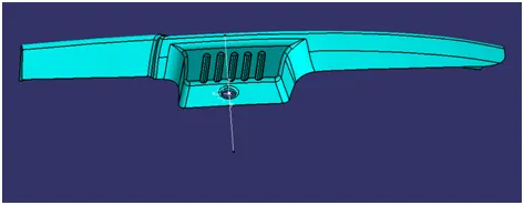
- Create a dummy tool axis on z direction using point – direction
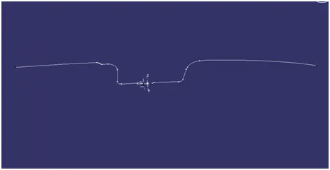
- Create a intersection on ZX plane for the given surface
.
- Create a point to point line as shown below
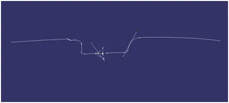
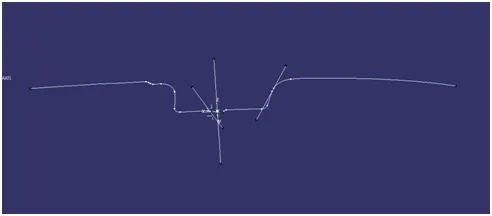
- Add bisecting line as shown below by the reference of two lines created above and named as TOOLING FACING X DRIECTION
- Create a intersection on ZY plane for the given surface
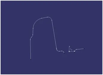
- Create a point to point line as shown below
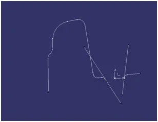
- Add bisecting line as shown below by the reference of two lines created above and named as TOOLING FACING Y DRIECTION
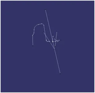
- Add bisecting line by the reference of tooling facing x direction and tooling facing y direction and named as tooling axis
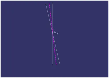
CREATION OF SIDE TOOLING AXIS Y
- Create a point on surface and create a line using point direction, use direction as y axis.
- Drag a compass and place it on axis that we created. Adjust the compass till we get correct view. lock the orientation of the compass.
- Modify the above line by changing the direction along compass
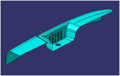
CREATION OF SIDE TOOLING AXIS X
- Create a point on surface and create a line using point direction, use direction as y axis.
- Drag a compass and place it on axis that we created. Adjust the compass till we get correct view. lock the orientation of the compass.
- Modify the above line by changing the direction along compass
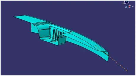
PERFORMING DRAFT ANALYSIS ON MODEL
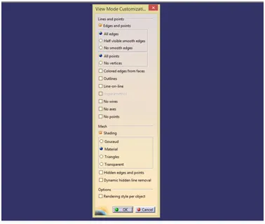
- To perform draft analysis open customize view parameters and choose the material
- Insert a feature draft analysis by following these commands
I insert>analysis>feature draft analysis
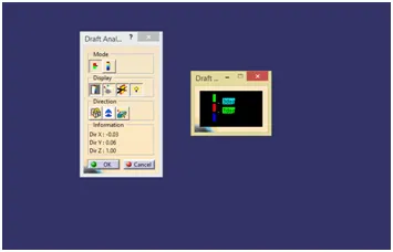
- Align the compass on tooling axis that we created
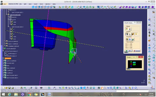
- Open the color scale and enter the value is 3 deg.
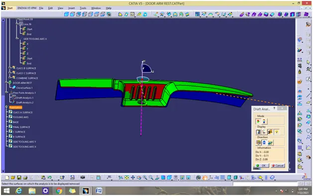
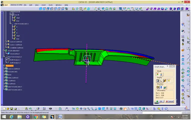
- If the whole body is green that all the faces is greater angle than the provided angle
DRAFT ANALYSIS REPORT OF CLASS A
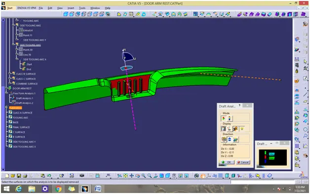
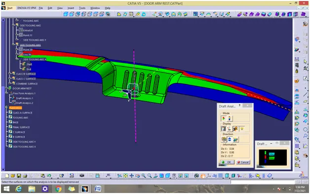
DRAFT ANALYSIS REPORT OF SOLID MODEL
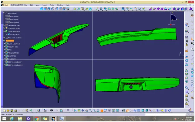
MODEL IN VARIOUS ORIENTATION
CONCLUSION
Thus the 3D model has been created using catia v5.