DEVELOPMENT OF DOORTRIM PANEL
FINAL PROJECT– DOOR TRIM
OBJECTIVES:
- To create individual tooling axis for the parts and perform draft analysis on the class A surface
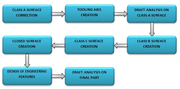
- To create the class B and class C surfaces from the given class A surface
- To form a solid geometry by combining all the surfaces
- To decide an attachment strategy for the part and create engineering features in reference from the master section provided
- To perform draft analysis on the solid part model with all engineering features
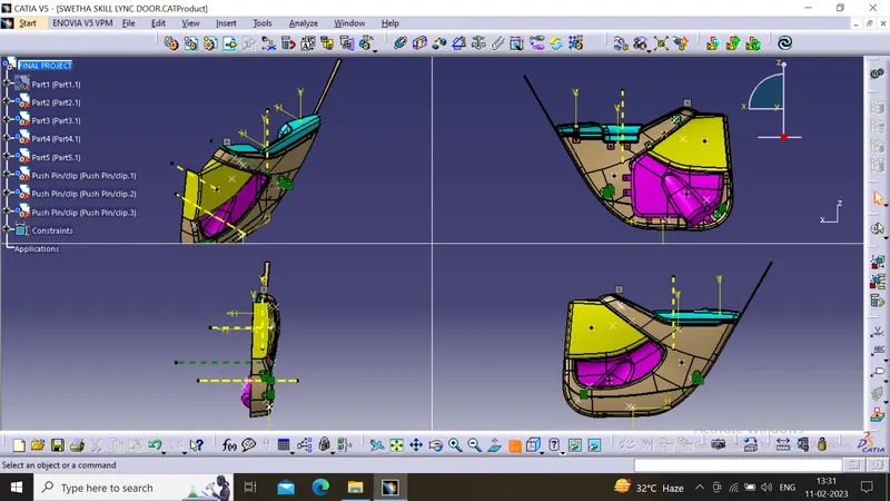
- To assemble all the components togehter to obtain the final trim
PROCESS OR METHODOLOGY
| CONSTRUCTION OF TOOLING AXIS : |
Tooling axis :
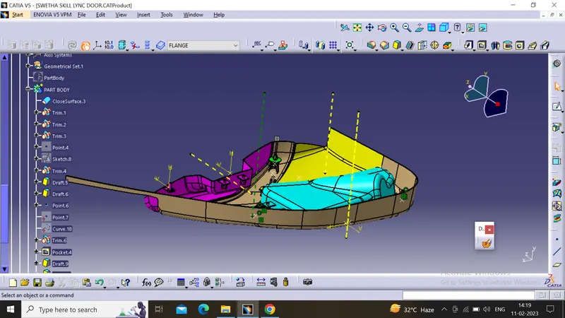
Tooling direction is basically the direction that mold pulls apart. The mold is built in two seperate pieces, basically you have a cavity side and you have core side, The core pulls apart from the cavity and that's the Tooling direction. While creating a Tooling direction make sure that waterver that is created that is going to be used as a reference to design it may also include Ribs, Pockets, Walls Bosses etc. All are going to be drafted with respect to Tooling axis to make sure that the core can pull apart from the cavity nice and clean.
Process :
since the extracted class A are of complex geometry for Bisection method to get the tooling axis ,even though we create it,it won't be accurate when we apply draft analysis on that tooling direction and also takes too much time and effort.so it is better if go with the trial method of moving compass until we get the satisfied analysis result to do that go to Insert > Analysis > Feature Draft Analysis and Simply place the compass on the largest flat surface then Check the Analysis by Tilting the Compass by Orientation or Rotation about an axis to get the desired result. After choosing the particular orientation,lock the compass direction.
now we have locked the definite direction of tooling axis now we will create a straight line which itself will be tooling axis.first we create a point on the surface before creating tooling axis .
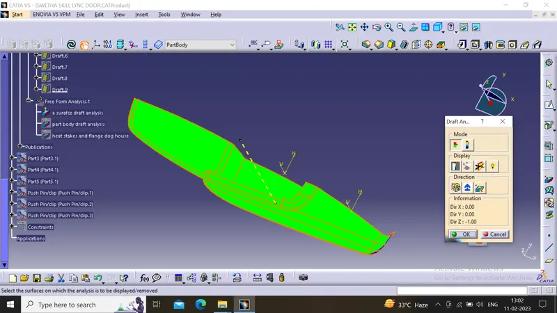
DRAFT ANALYSIS REPORT ON CLASS-A SURFACE
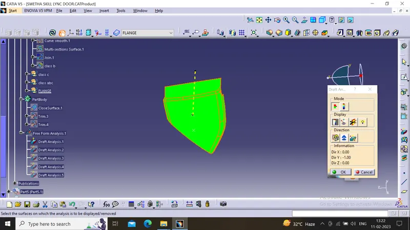
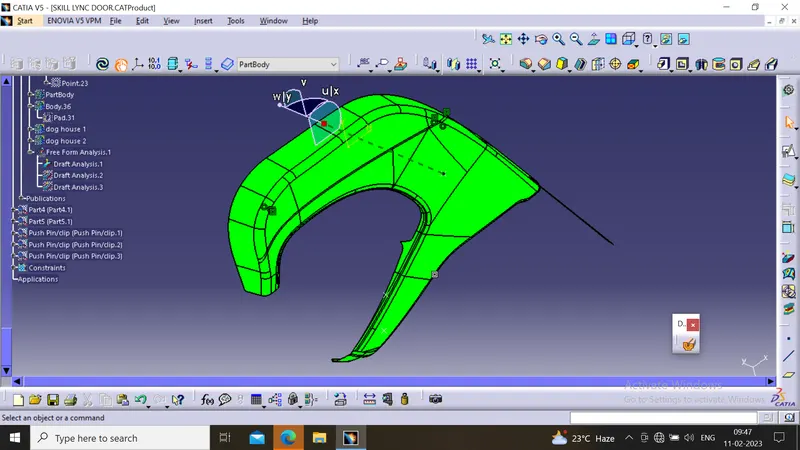
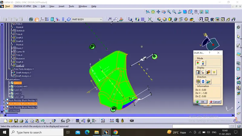
Our first step before starting the model should always be to check is the surface has enough draft that it will not create any problems while ejecting from the mold. This seems like a big task as we have to foresee something that will come at very later stage. But this is done by a small process called draft analysis. This analysis tells us whether our component will be safely ejected in the tooling axis we have provided. Some components require side core where there are under undercuts, holes or projections on the side walls, so for this we need a different tooling axis and a different analysis is required to check those areas. .We have to make sure that our entire model is green which means it is clearing the analysis. So we have to run analysis for class-A, solid model and other B-side features as every single component, regardless of its size should be ejected safely from the core.
1.DOOR ARM REST
2.MAP POCKET
3.LOWER SUBSTRATE
4.BOTTLE HOLDER
Class A surface
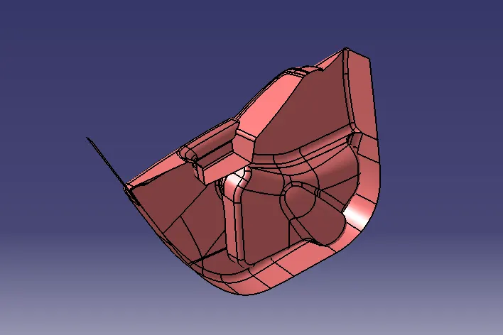
Class A surface for the Automotive door panel is received from the stylish team, In the automotive Industry for Class A surface Separate team is allowed to design Class-A surface this is the first input for design for plastic parts.
CLASS B SURFACE:
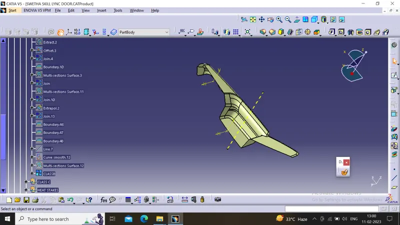
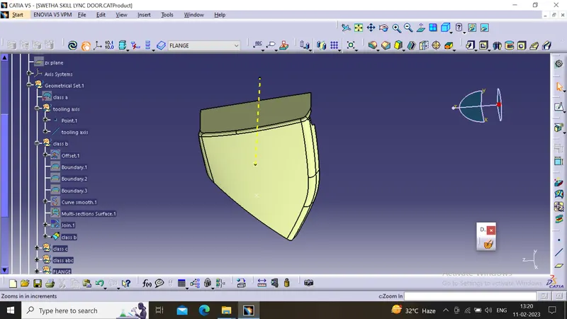
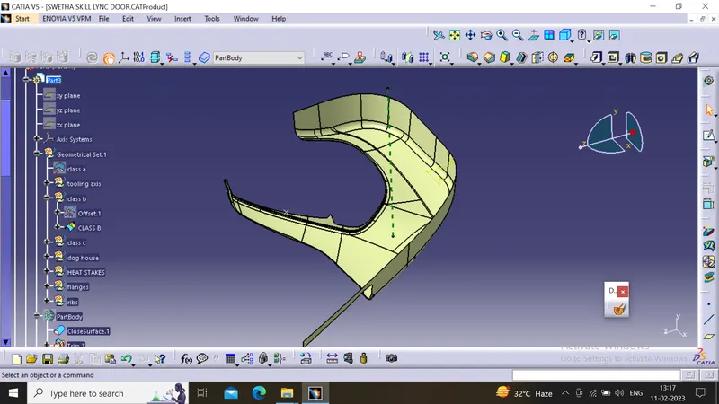
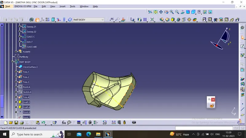
- After all the validation has been done, the class B surface is created by offsetting the class B surface to a distance of 2.5 mm
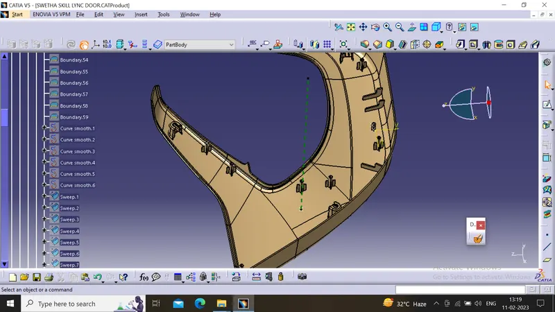
- After offsetting many openings in the surfaces are found which are closed with the help of multi sections-surface and sweep commands.
- The class B surface is then extrapolated in parts to trim it along with the class C surface
COMMANDS USED IN CREATION OF B SURFACE
1.offset
2.extrapolate
3.extract
4.boundary
5.sweep
6.multi section surface
7.join,trim,split
1.DOOR ARM REST
2.MAP POCKET
3.LOWER SUBSTRATE
4.BOTTLE HOLDER
CLASS C SURFACE:
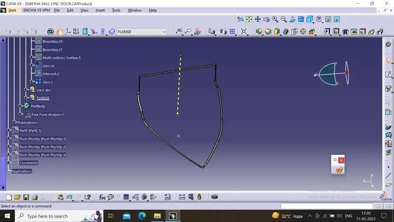
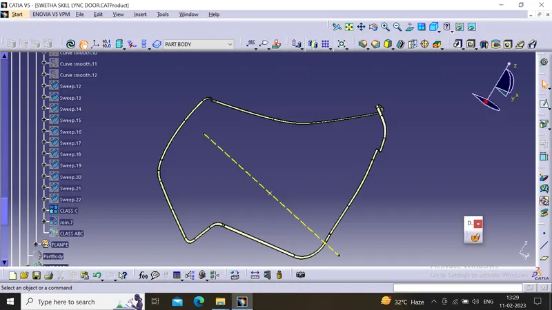
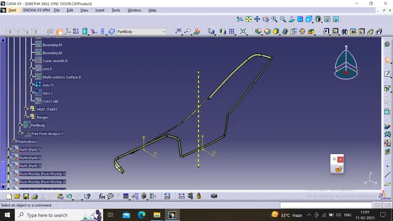
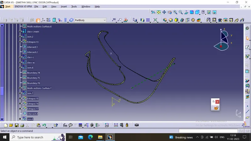
- The class C surface which connects the class A and class B surface is created by sweeping the boundary of the class A and using the class A as a reference.
- The sweep is divided into several parts in order to avoid complexity
- Surfaces which are parallel to the tooling direction are swept with the tooling axis as reference and with a draft angle of 3 degrees
- C surface is the part of the geometry that connects Class A with B surface.Rules to be followed for C surface creation is A minimum draft of 3 degrees should be provided to facilitate the Ejection of the Molded component.The parting line should be on the B surface. This means that the draft should sweep outwards, from the C surface
1.MAP POCKET
2.BOTTLE HOLDER
3.DOOR M RESTAR
4.LOWER SUBSTRATE
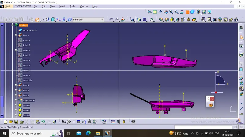
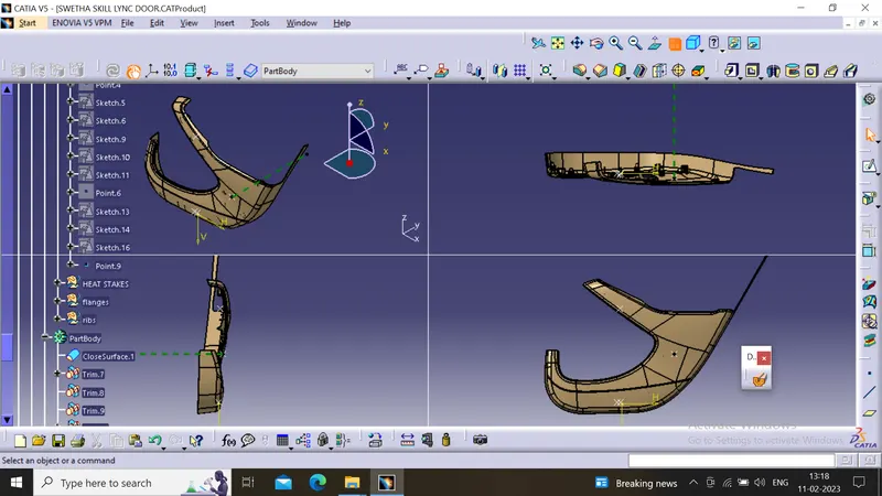
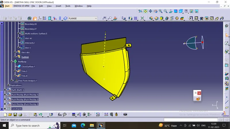
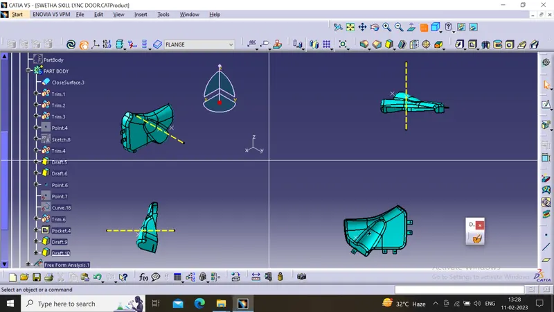
CLOSED SURFACES[PART BODIES]
1/ARM REST
2.LOWER SUBSTRATE
3.MAP POCKET
4.BOTTLE HOLDER
ENGINEERING FEATURES:
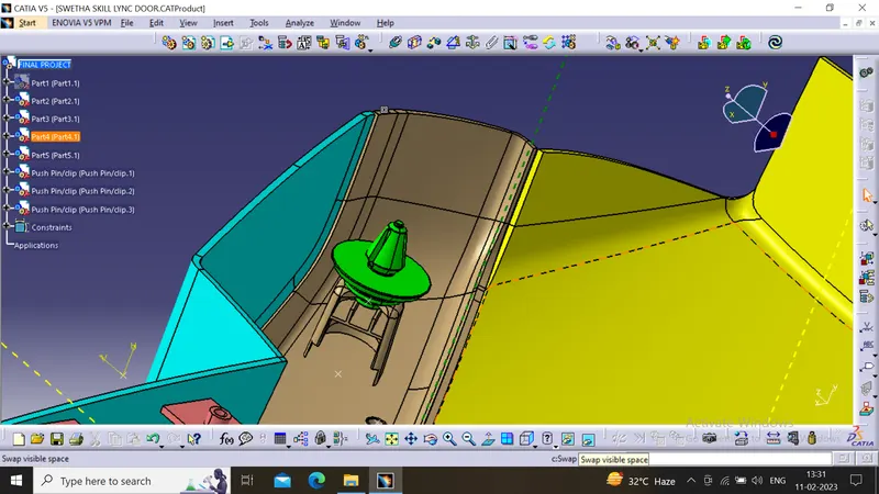
DOG HOUSE WITH PUSH PIN:
- The two main purposes of a dog house are to avoid sink marks and to house various other engineering features like screw boss, locators, push clips etc.
- In this case, the dog house is designed to house the push clips and the 4 way locator. The dog house designed for the push clip features a slot on the top face to accommodate the push clip
- The dog house should follow certain design rules which are stated below
HEAT STAKE,FLANGES,LOCATORS
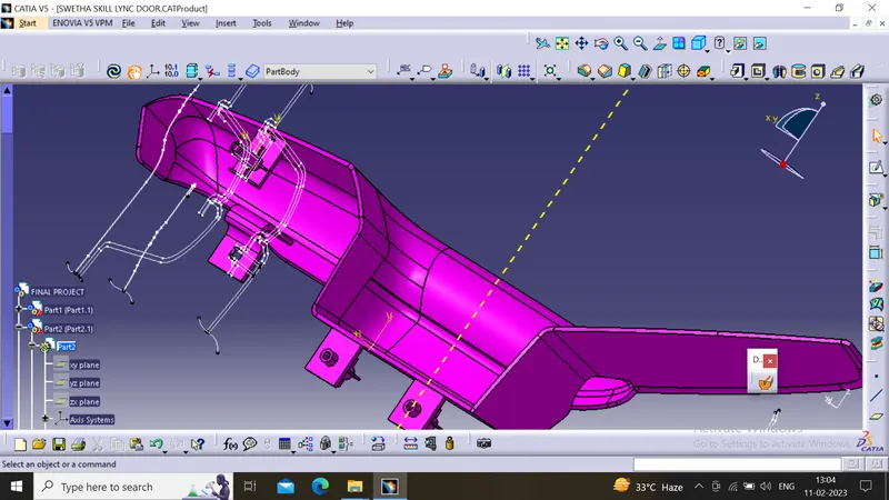
- Heat stakes are used in thermoplastics to assemble two parts together by locally heating and cooling the plastic MATERIAL
- and allowing it to reform itself and act as a joint for the two materials.
- We have placed 9 heat stakes in the model based on the reference points created by estimation.
- One of the important factor to be considered while designing the heat skates is the height of the heat skates. It should always be less than the height of the locators
LOCATOR:
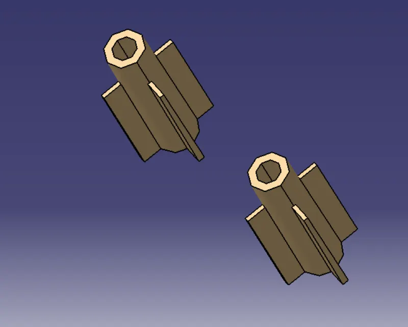
- The main purpose of locators is to facilitate proper locking of two components together while assembling and arrest the maximum degrees of freedom possible.
- These locators are similar to guide pins provided in mould.
- The two types of locators used are two way locator and four way locator.
- We have positioned three 4 way locators in our model which meet the rib design criteria.
- Loctors which where violating the height rule were placed on a dog house to avoid any defects while manufacturing and also possible failures during assmebly.

FINAL DRAFT ANLAYSIS
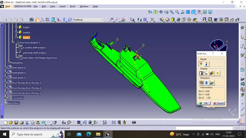
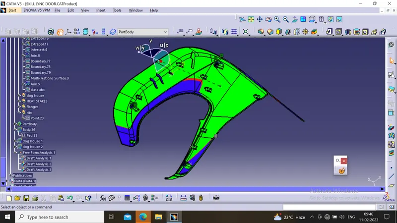
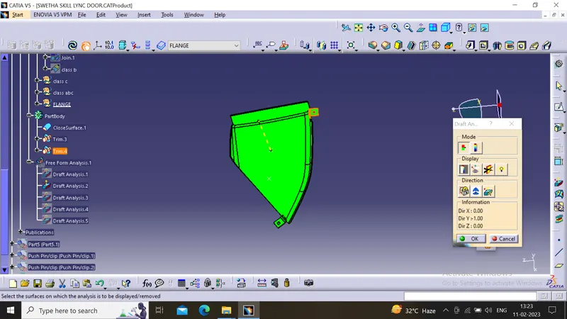
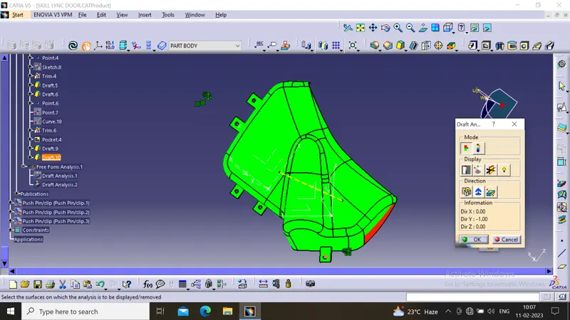
DRAFT ANALYSIS ON PART:
- Draft analysis is done on the final part with the tooling axis as reference
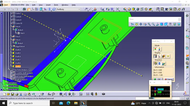
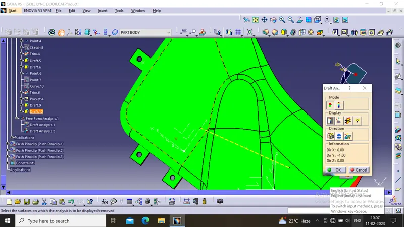
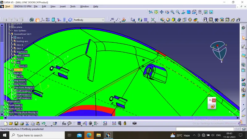
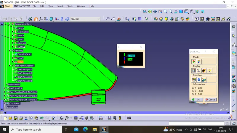
- Green surface indicates the areas where the draft is more than 0.5 degrees.
- Red surface indicates the areas having negative draft.
- All the engineering features are given a draft with reference to the tooling axis and hence they can be cleared in the main tooling
- Lifter axis for clearing the dog house inner surfaces are provided for each individual dog house
DRAFT ANALYSIS ON ENGINEERUMNG FEATURES[FLANGES,HEAT STAKES,RIBS,DOGHOUSE]
1.ARM REST
2.BOTTLE HOLDER
3.LOWER SUBSTRATE
4.MAP POCKET
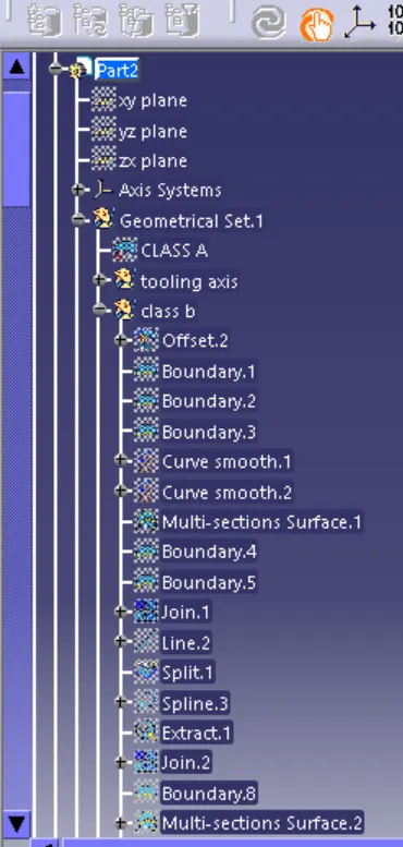
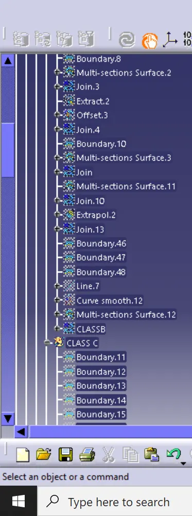
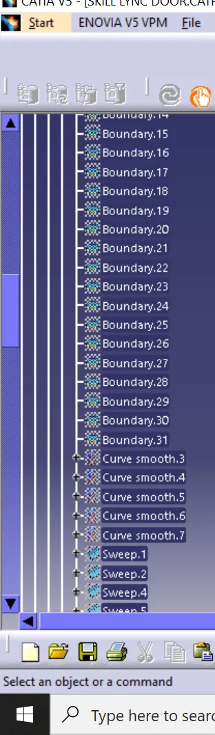
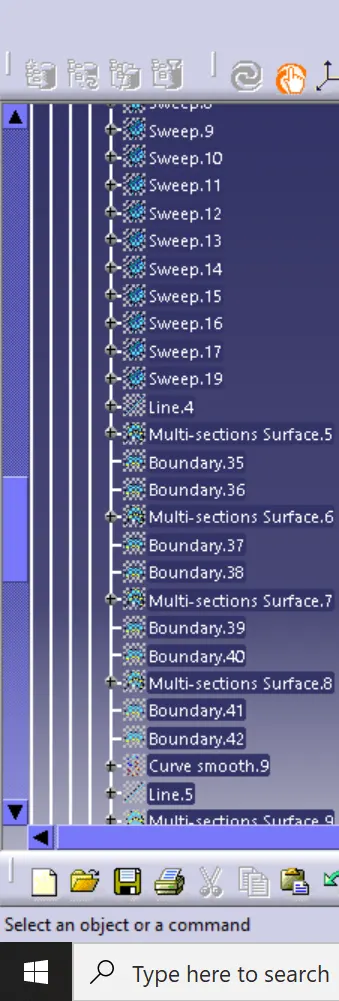
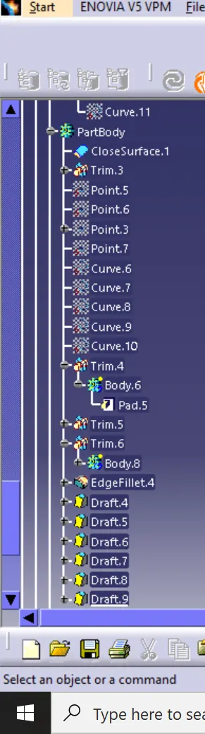
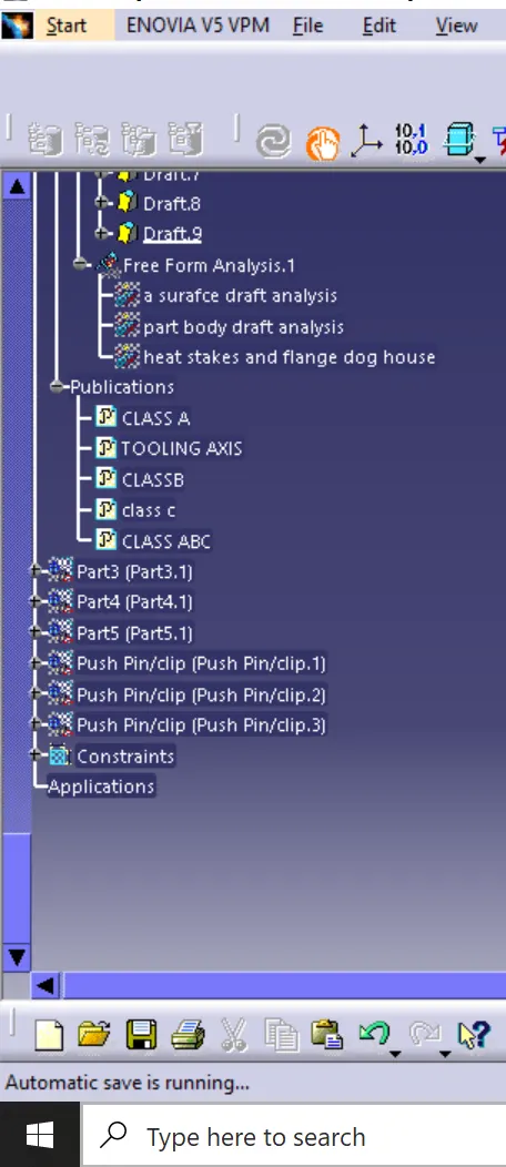
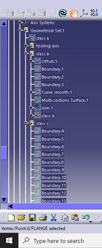
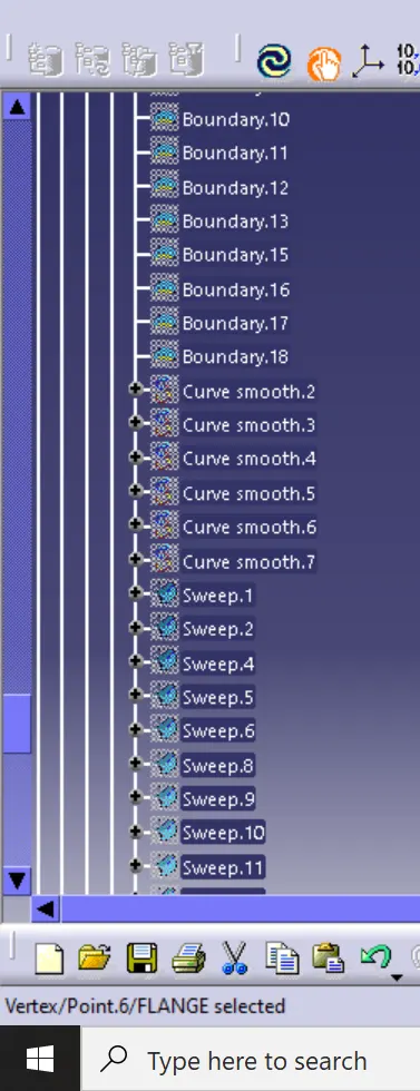
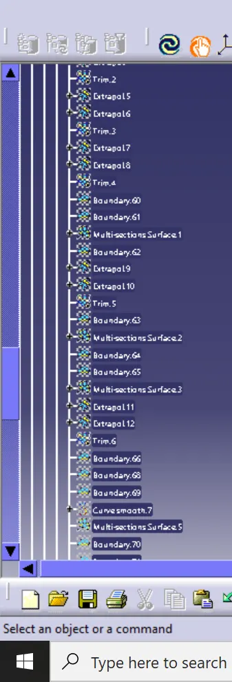
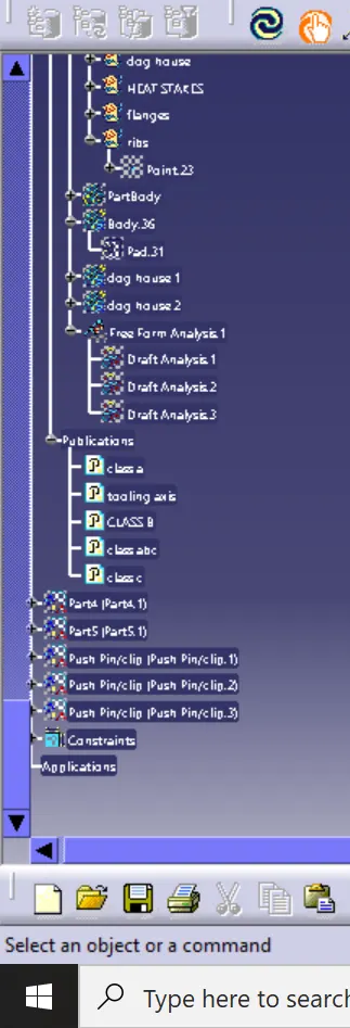
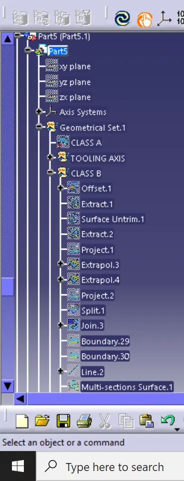
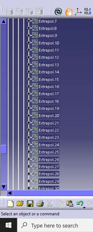
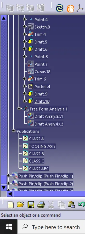
TREE STRUCTURES
1.ARM REST
2.MAP POCKET
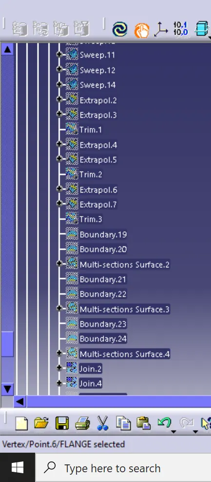
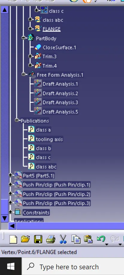
3.LOWER SUBSTRATE
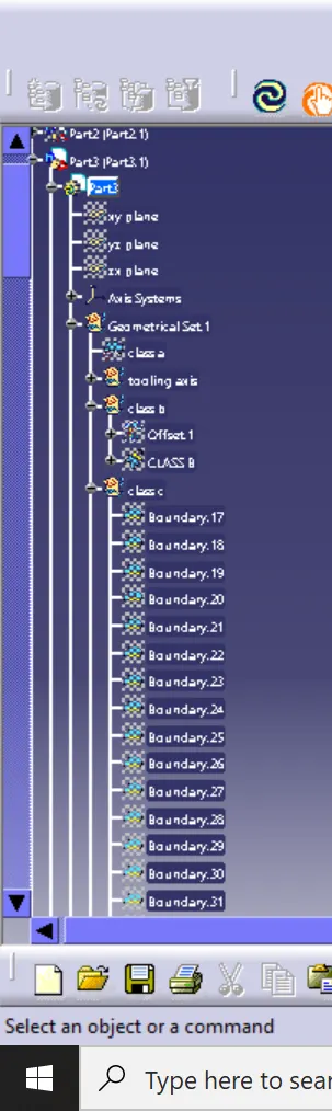
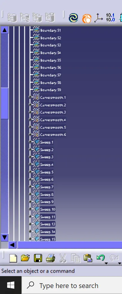
4.BOTTLE HOLDER
FINAL PART...
CONCLUSION
The Door panel has been successfully designed by following GUIDELINRESs used in the automotive industry. all the attachment features are properly placed at different locations. the designed parts meets all the designed objrctives.