Development of Door Bell Used for Home and Thermistor to Sense the Temperature of Heater using MATLAB & SIMULINK
Aim - To develop the MATLAB SIMULINK model for Door Bell for Ringing Application and Thermister to sense the temperature of the Heater.
Part 1: Simulink Model of Doorbell using the Solenoid Block
Solenoid -
Solenoids are very commonly used actuators in many process automation systems. There are many types of solenoid, for instance there are solenoid valves which can be used to open or close water or gas pipe lines and there are solenoid plungers which are used to produce linear motion. One very common application of solenoid that most of us would have come across is the ding-dong door bell. The Doorbell has a plunger-type solenoid coil inside it, which when energised by AC power source will move a small rod up and down. This rod will hit the metal plates placed on either side of the solenoid to produce the soothing ding dong sound.
Although there are many types of solenoid mechanisms available, the most basic thing remains the same. That is, it has a coil wound over a metal (conductive) material. When the coil is energised this conductive material is subjected to some mechanical movement which is then reversed through a spring or other mechanism when de-energised.
What is Solenoid and how does it works?
A solenoid is a device that converts electrical energy into mechanical energy. It has a coil wound over a conductive material, this set-up acts as an electromagnet. The advantage of an electromagnet over natural magnet is that it can be turned on or off when required by energising the coil. Thus when the coil is energised then according to faradays law the current-carrying conductor has a magnetic field around it, since the conductor is a coil the magnetic field is strong enough to magnetise the material and create a linear motion.
Door Bell -
Fig - Diagram Indicating Door Bell
In door bell arrangement, when the switch is closed the electromagnet receives electrical power from the battery and pulls the metal arm to hit the bell producing sound.
To create a model of the doorbell in SIMULINK I had search out for the block which are going to be used in the model from the MATLAB library.
- Search for source in library browser. I got the block with name pulse generator which will be providing signal source for my model.
- The signal output of the pulse generator is not physical for our SIMSCAPE block so I attached Simulink to PS Converter and used it to convert the signal.
- Switch is attached along side of Battery to on and off the switch for battery supply.
- Electrical Reference is used to ground the electrical block.
- Solenoid is connected in the circuit which will work as door bell for our model.
- After solenoid Ideal Translational Motion Sensor is connected to sense translatory motion of the plunger.
- The output of the translational sensor is given to the scope through PS - Simulink converter.
- Solver configuration is connected in the circuit to solve this simulation.
- Mechanical Translational Reference is used to ground the mechanical block in the circuit.
Explanation - The signal is drawn from the pulse generator to trigger the circuit. As per the question the switch is to be closed for 2 sec and then released so we give input value for time period as 4 sec and to trigger the switch for 2 sec the pulse width as 50 % of the pulse period. We get input as below image from the pulse generator.
fig - Pulse Generator Signal
fig - Circuit Diagram for Door Bell
Battery supply the current in the circuit and the switch is closed for the 2 sec. When the current pass through the solenoid the plunger moves from its initial position of 5 mm and moves toward c port to ring the bell at position 0 mm. For doing this so we change the mechanical & variable parameter in the solenoid. This motion of the of the plunger is sensed by motion sensor and its output in the form of position is checked through the scope attached in the circuit.
Output:
fig - Output plot of the Door Bell Plunger
From this graph we can say that the plunger is moving from its initial position of 5 mm with phase delay of 2 sec then it rings the bell when it comes to 0 mm for 2 sec between 2-4 sec and then again it goes to its initial position of 5 sec after ringing the bell.
Part 2: Simulink Model to sense the temperature of heater using Thermister
Thermister -
A thermistor is a device or a sensor used to regulate and measure the temperature such as hot or cold. Thermisters measure the temperature as a function of change in potential difference at constant current or a change in current at constant temperature. These temperature sensors are constructed of semiconductor materials, and their resistance is either a direct or inverse function of temperature.
In this application, the thermistor is used to protect a circuit by limiting the amount of current that can flow into it. If too much current starts to flow into the circuit through the thermister this cause the thermistor to warm up.
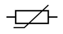
Symbol of General Thermister -
Signal Builder for Heater Temperature:
Here Signal builder block is used get temperature signal for the controlled temperature source (heater). For 0-10 sec the temp value is 293K (20 deg), 10 - 30 sec the temperature value is 300K (27 deg) and for 30 - 50 sec the value of the temperature is 296K (23 deg) as per the problem statement. This signal is provided to our heater through port S and port is linked with the thermal reference.
Fig - Signal Building to Heat Heater
Block Diagram of Simulink Model:
Fig - Circuit Diagram to sense the Temperature
Explanation of Block Diagram:
The temperature of heater is supplied to thermister to sense it. Now in order to run the fan when the temperature reaches the value of 25 deg (298K) we have to trigger the circuit with some external supply of battery and as there is no device to calculate the resistance value from the thermistor for that we attach another another resistor is series across thermister. The voltage sensor is attached across the resistor to calculate the voltage drop into it and this voltage drop value is inputted as a threshold value to the switch to start the fan. The fan will get on when the threshold value is greater than 0.109.
The output of the Model:
Fig - Plot of Fan Operation
From the graph we can say that when temperature is 20 deg(239K), the fan was off. After that when it reaches to temperature more that 25 deg (298K) fan gets On and again when the temp condition reaches to 23 deg (296K) fan get switch off.
Conclusion -
This way we created the Door Bell for ringing application and Thermister to sense the temperature of the Heater in MATLAB & SIMULINK. I can conclude that this model development is very useful to develop the other models by learning the circuit diagram of various day to day components.