Developing a Door Trim Panels
Objective: Creating a Door trim panel from given class A surface by using Catia V5 .
Given below is the procedure to create a new plastic component from given class A surface .
- Creation of tooling axis
- Creation of class b surface
- Creation of class C surface
- Creation of closed body
- Draft Analysis
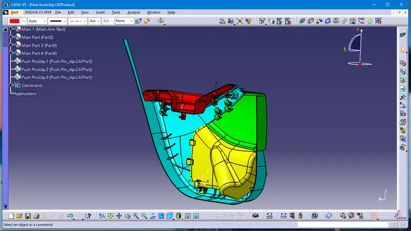
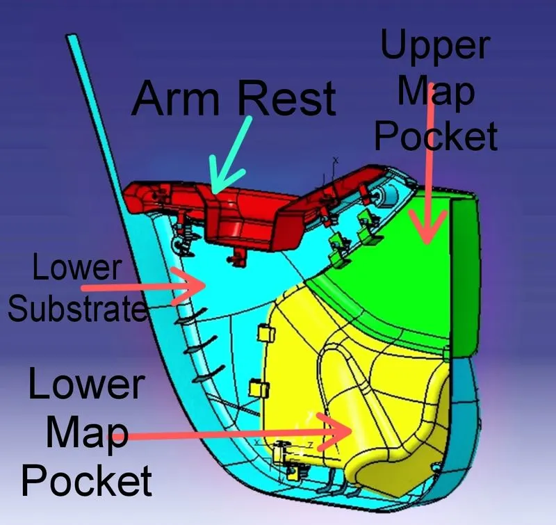
The Main Components in the given Surface is:
1) Arm rest
2) Map pocket (Consists of upper and lower part)
3) Upper substrate (Not given in the current model)
4) Lower substrate .
Class A surfaces of all parts:
Refers to those surfaces which are visible in a product either interior or exterior. This service is primarily used in the automotive environment and increasingly in consumer goods. It is a requirement where aesthetics have a significant contribution.
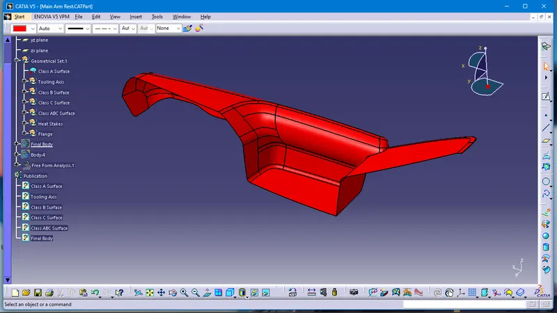
Arm Rest:
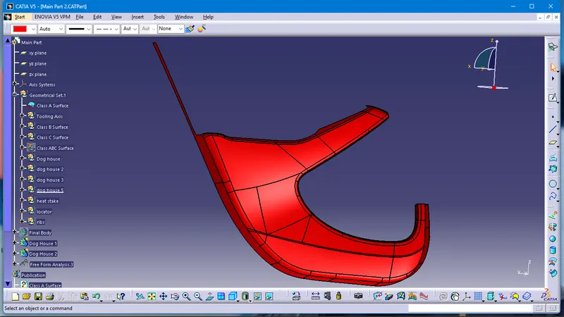
Lower Substrate:
Upper Map Pocket:
Lower Map Pocket:
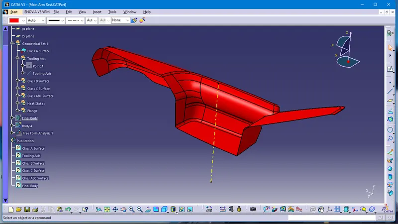
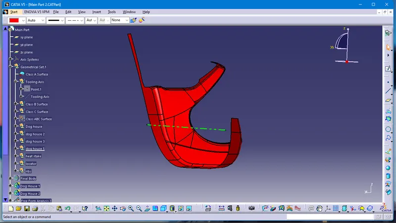
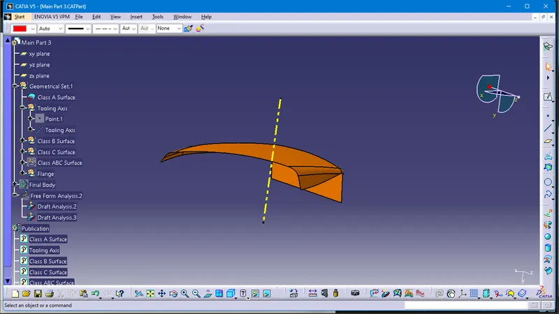
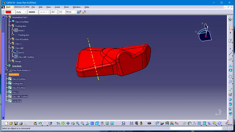
Creation of Tooling axis:
Arm Rest:
Lower Substrate:
Upper Map Pocket:
Lower Map Pocket:
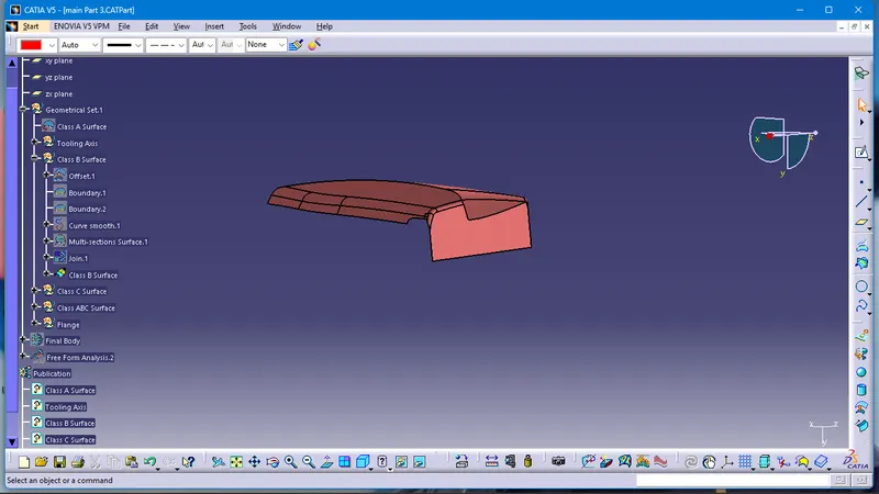
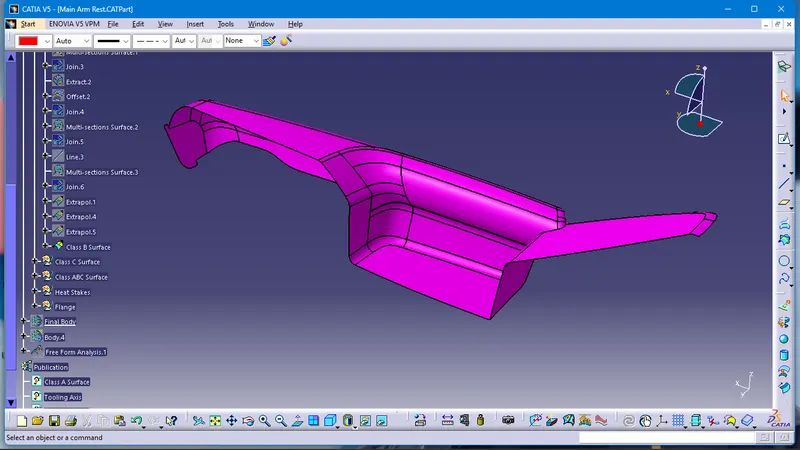
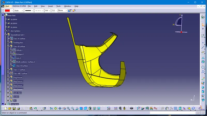
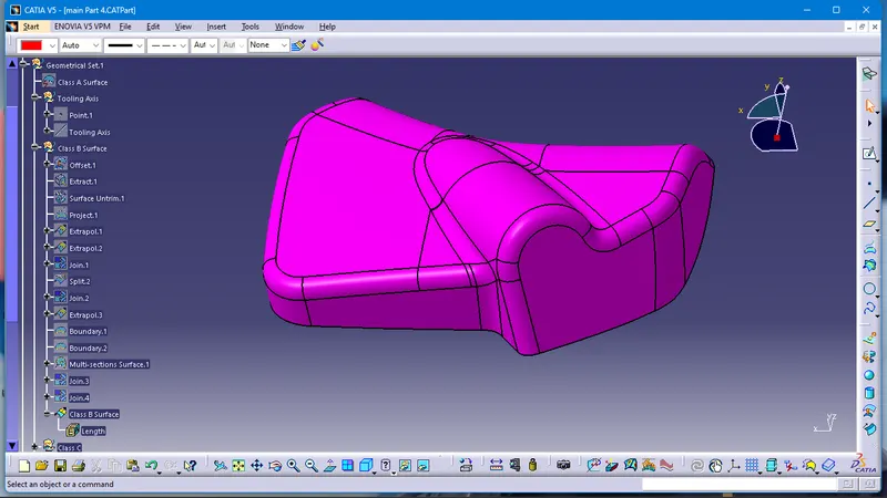
Creation of class B surface:
Procedure to create class B surface for Lower substrate .
Step 1: Use offset tool with a distance value of 2.5mm to create offset of class A surface .
Step 2: After offsetting , extrapolate tool was used to extend all the edges of this surface . This is done to ensure that the parting line comes at B surface .
Step 3: In areas where extrapolate was not possible (Fillet or cusped surfaces) multisection surface option was used .
Arm Rest:
Lower Substrate:
Upper Map Pocket:
Lower Map Pocket:
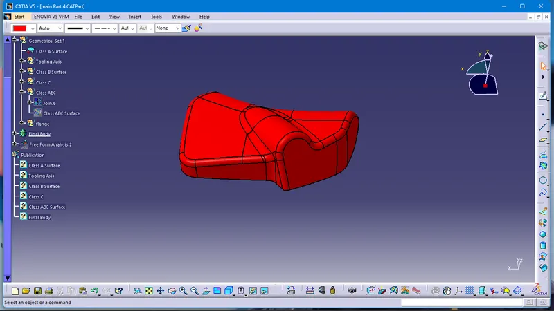
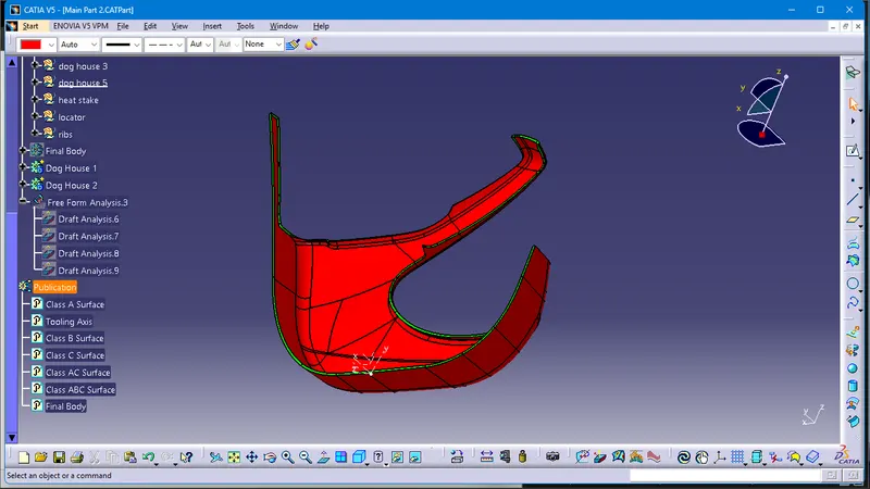
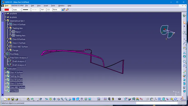
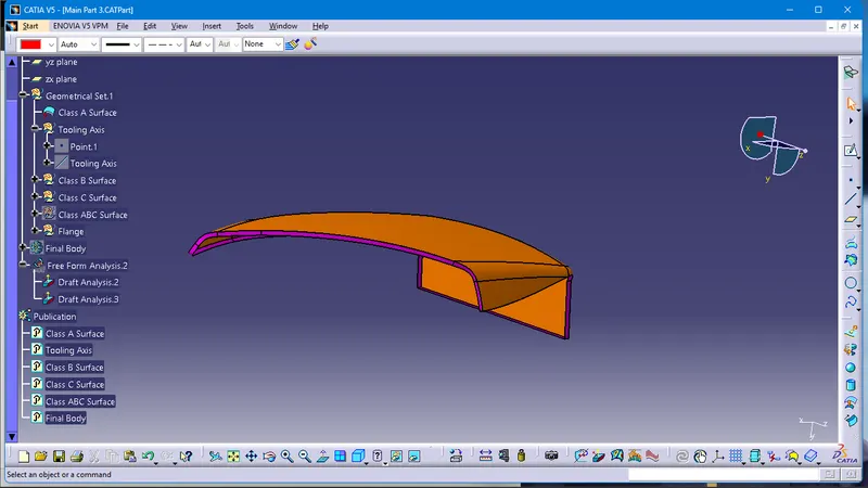
3) Creation of Class C surface
Procedure for creation of class C surface for Upper map pocket
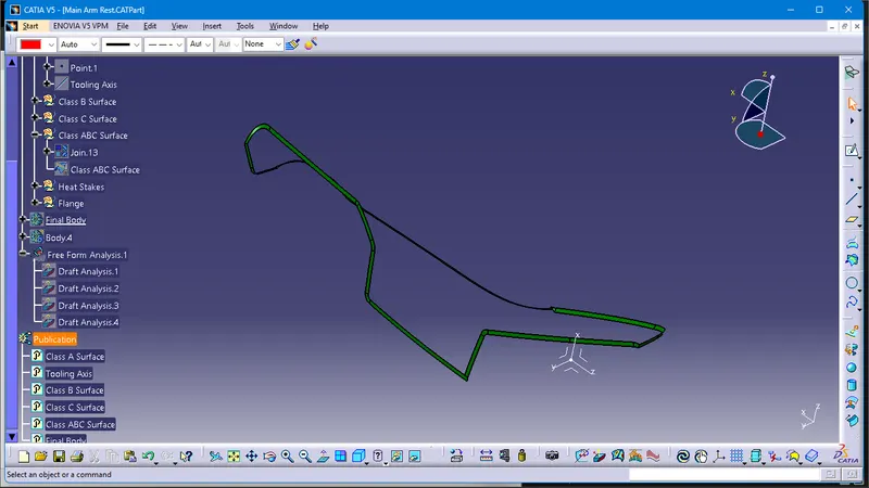
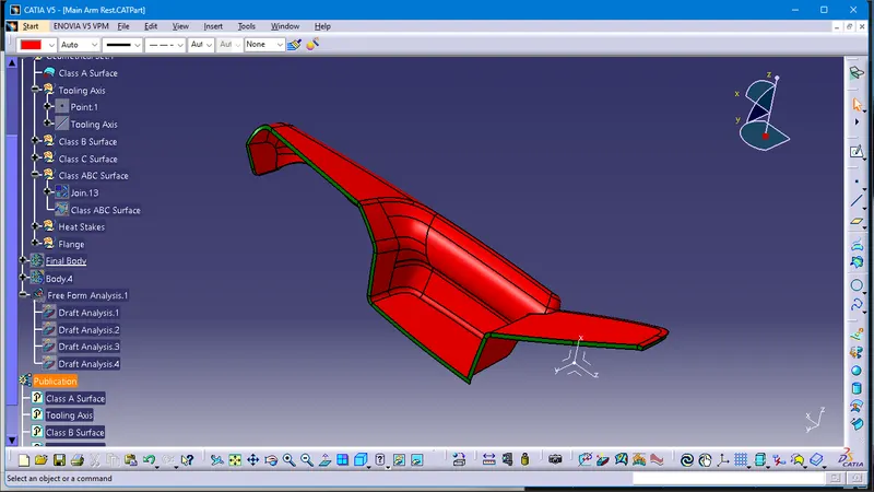
Step 1: Use sweep command to create a new surface an an angle with respect to a surface . This angle is dependant on draft angle for free edges and ususally 90 degree for mating surfaces .
Arm Rest:
Lower Substrate:
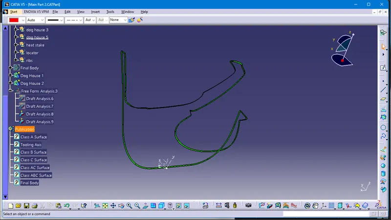
Upper Map Pocket:
Lower Map Pocket:
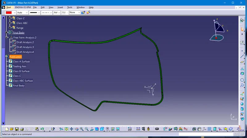
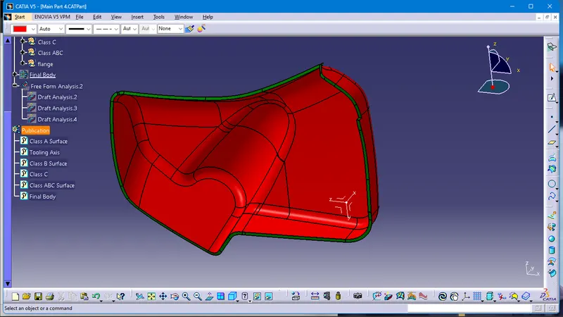
Hence class C was created for all components .
Creation of Closed Body:
Arm Rest:
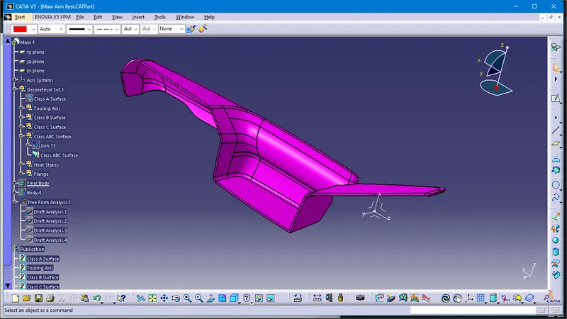
Lower Substrate:
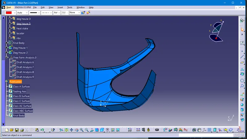
Upper Map Pocket:
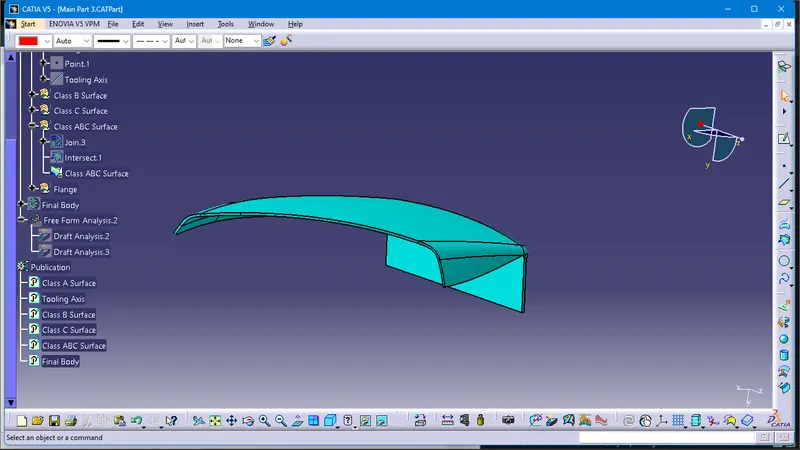
Lower Map Pocket:
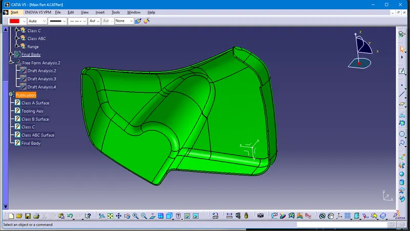
Push Pin Clip:
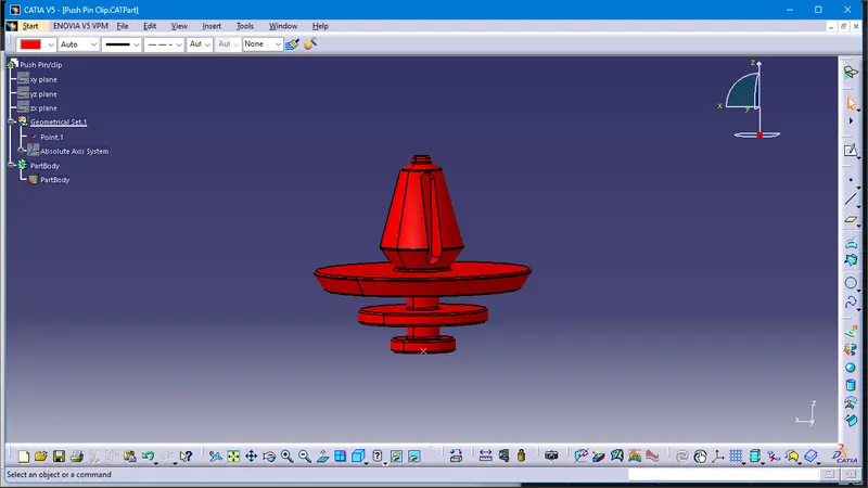
Heat Stakes:
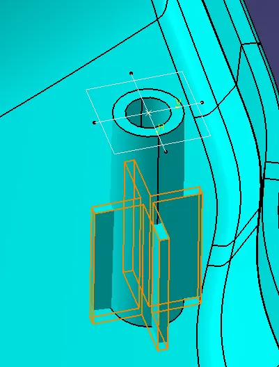
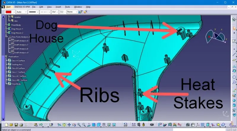
Dog House:
Step 1: Create a point on required location and a plane from it . Create a sketch with base sketch for dog house .
Step 2: Use sweep tool to create a surface using this profile and draft direction at a draft angle of 1.5 degrees.
Step 3: Use extrapolate and extrude option to create required surfaces and use trim and split to obtain the outer body of dog house .
Step 4: Create a new body and name it as dog house 1 . Use thick surface option to create a solid of required thickness .
Step 5: To create ribs, create and sketch and use pad tool to create a solid and union trim it with dog house .
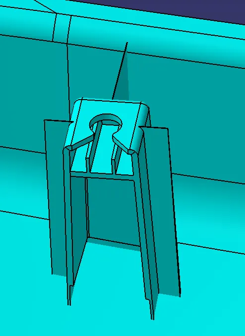
Creation of Ribs:
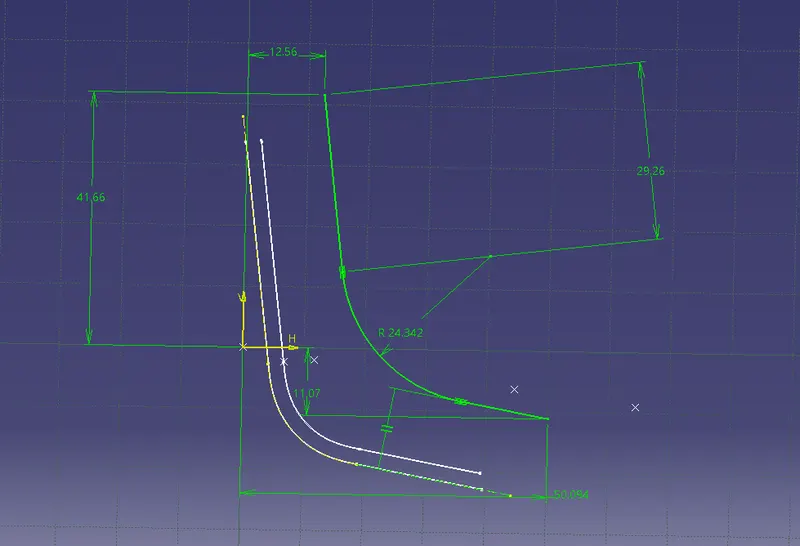
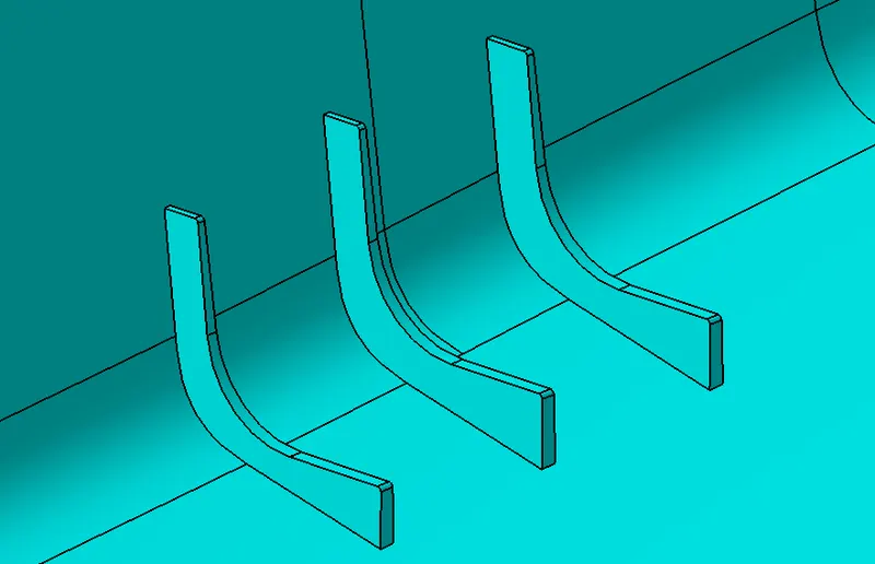
Step 1: Create a sketch and create a surface . Use thick surface option to obtain ribs in required shape .
Step 2:Use Translate option to place ribs wherever required.
- Use Boolean operation union trim to trim it with lower substrate main body .
- Create heat stakes and flanges at required locations using above mentioned procedures to obtain complete substrate body . Apply draft on all required surfaces and fillets on all straight edges.
Dog House, Ribs & Heat Stakes:
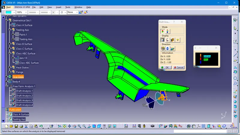
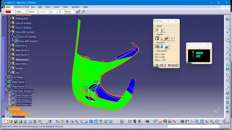
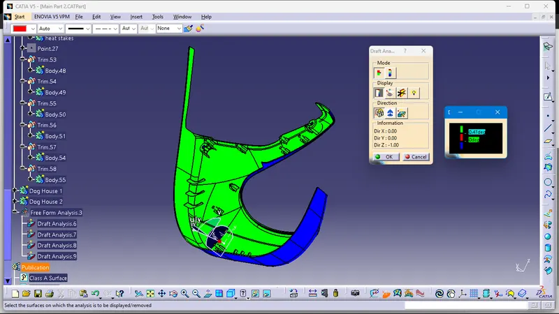
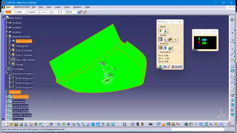
Draft analysis :
1)Once the tooling axis is created , publish it and the component using Publication from tool option .
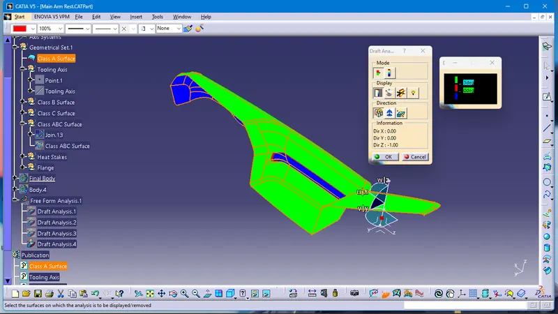
2)Insert Feature draft analysis option from insert tool bar
3) Change the view option to customize view parameters and click on material option under shading .
4) Now click on the axis option from Draft analysis tools , allign it with tooling axis and click on lock option to lock it .
5) Change draft angle value to 3 degree . Click on quick analysis mode to display feature according to given color scale . Check from all views to ensure the draft analysis is cleared .
6) Since the created tooling axis does not clear the draft analysis at the created axis , click on the lock axis button to unlock it . Now rotate the tooling axis by left clicking on the top round portion of the axis system . Rotate the axis till maximum clearance is obtained . Now right click on the axis and click lock current axis .
7) Create a line using the initial axis origin and this axis using point and direction (using compass direction) option . This is our required tooling axis .
8) Now if we check for draft analysis, we can observe that the ribbed area has not yet cleared draft analyisis. Hence we need to create a side core tooling axis . To do this , create a line using point and direction option with Y direction .
9) Repeat steps 1 to 5 to ensure the remaing portion which was not cleared using Tooling axis has been cleared using this axis .
Arm Rest of Class A & Final Body:
Lower Substrate of Class A & Final Body:
Upper Map Pocket of Class A & Final Body:
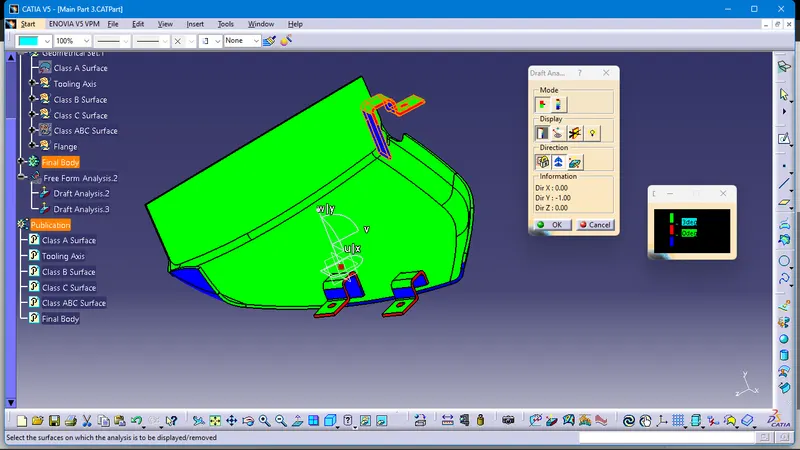
Lower Map Pocket of Class A & final Body:
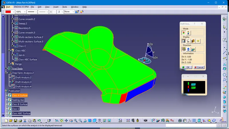
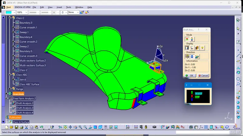
Push Pin Clip:
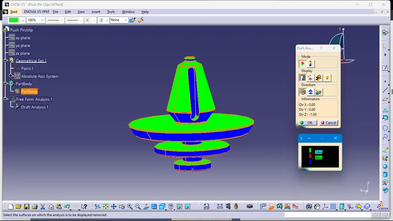
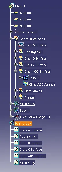
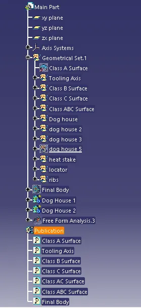
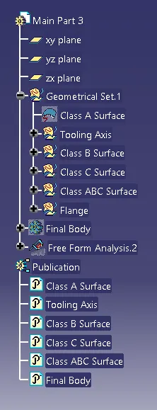
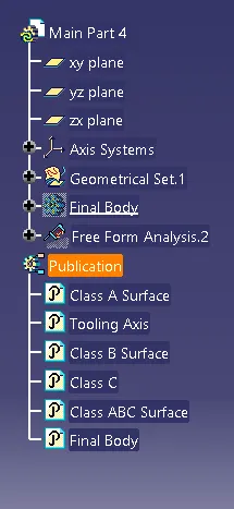
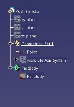
Tree Structure Developed:
Arm Rest:
Lower Substrate:
Upper Substrate:
Lower Substrate:
Push Pin Clip:
Final Assembly:
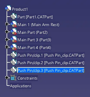
Completed model after all attachment features: