Designing and Assembly of Butterfly Valve using NX CAD
Aim :- To model and assemble Butterfly Valve and apply GD&T to the butterfly Valve.
Introduction:-
A butterfly valve is a valve that isolates or regulates the flow of a fluid. The closing mechanism is a disk that rotates.
A butterfly valve is from a family of valves called quarter-turn valves. In operation, the valve is fully open or closed when the disc is rotated a quarter turn. The "butterfly" is a metal disc mounted on a rod. When the valve is closed, the disc is turned so that it completely blocks off the passageway. When the valve is fully open, the disc is rotated a quarter turn so that it allows an almost unrestricted passage of the fluid. The valve may also be opened incrementally to throttle flow.
Procedure:-
For modeling and assembly of butterfly valve different parts of butterfly valve was designed such as
- Body
- Shaft
- Disc plate
- Retainer
- Lever
- Nut
- Screw
For modeling above parts different Commands were used such as
- SKetch:- Sketch is used to creat a 2D drawing which is later used to form 3D model.
- Extrude:- It extrudes the sketch or selected sketch contours in one or two directions to creat a solid feature.
- Hole:- A Hole feature is used to create holes on the model.
- Unite:- Unite is used to convert two or more solid bodies into one solid body.
- Revolve:- It revolves a sketch or selected sketch contours around an axis to create a solid feature.
- Chamfer:- Chamfer is used to connect two adjacent faces using an inclined line.
Overview of parts of Butterfly valve:
1] Body of butterfly valve
- Initially, the sketch for the body of butterfly valve is drawn using the sketching tools in NX CAD.
- After that sketch is Extruded, then ears of the butterfly valve is drawn and is copied on both sides of the cylindrical portion, then it is extruded.
- Now a new plane is crated on the surface of cylinder using datum plane option and cylinder is created on that plane. then, Hole command is used to create a counter bore on that cylinderical surface.
- Finally, three holes are created for mounting of the body and then, the part is saved.
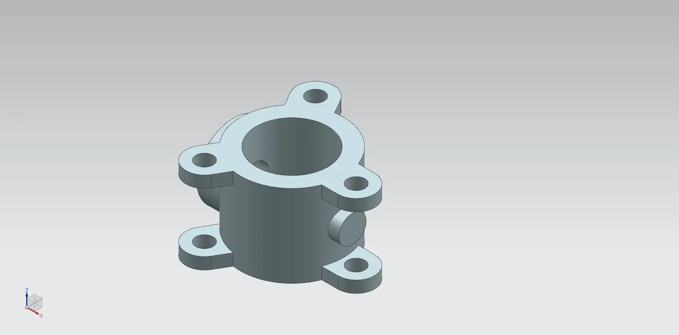
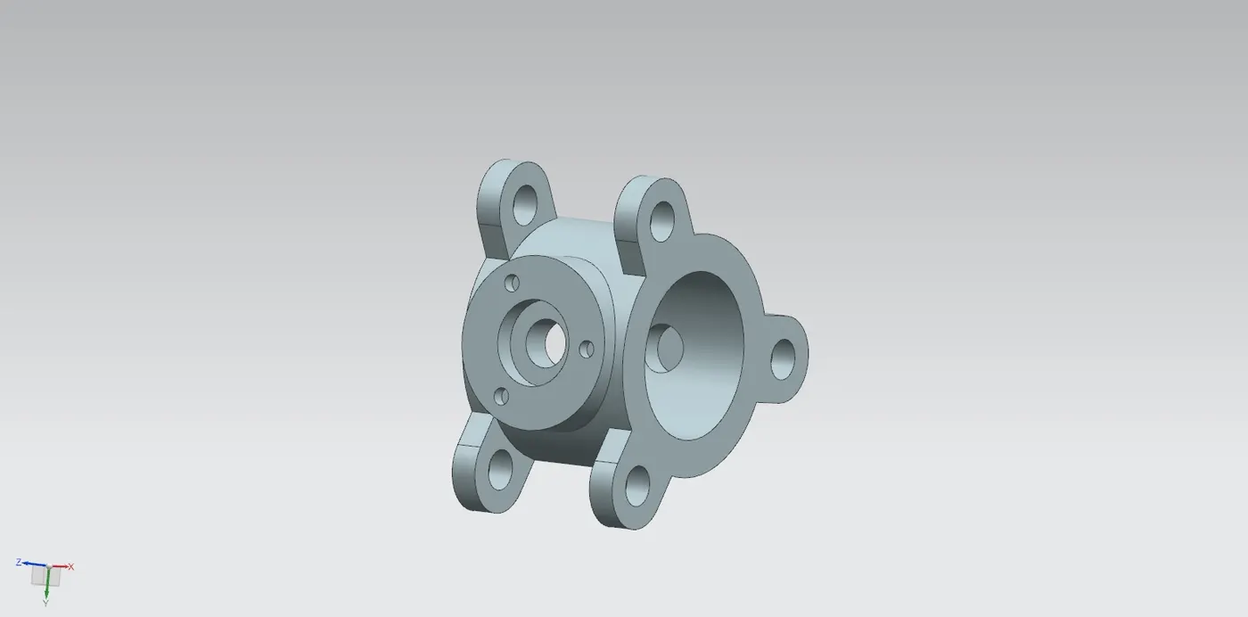
2] Shaft
- Sketch is created on a plane then, Revolve command is used to get the desired shape of the shaft.
- Then Extrude command is used to create a recess portion in the front and rear portion of the shaft.
- Finally, two holes of 12.5mm diameter is created in the rear recess portion of the shaft.
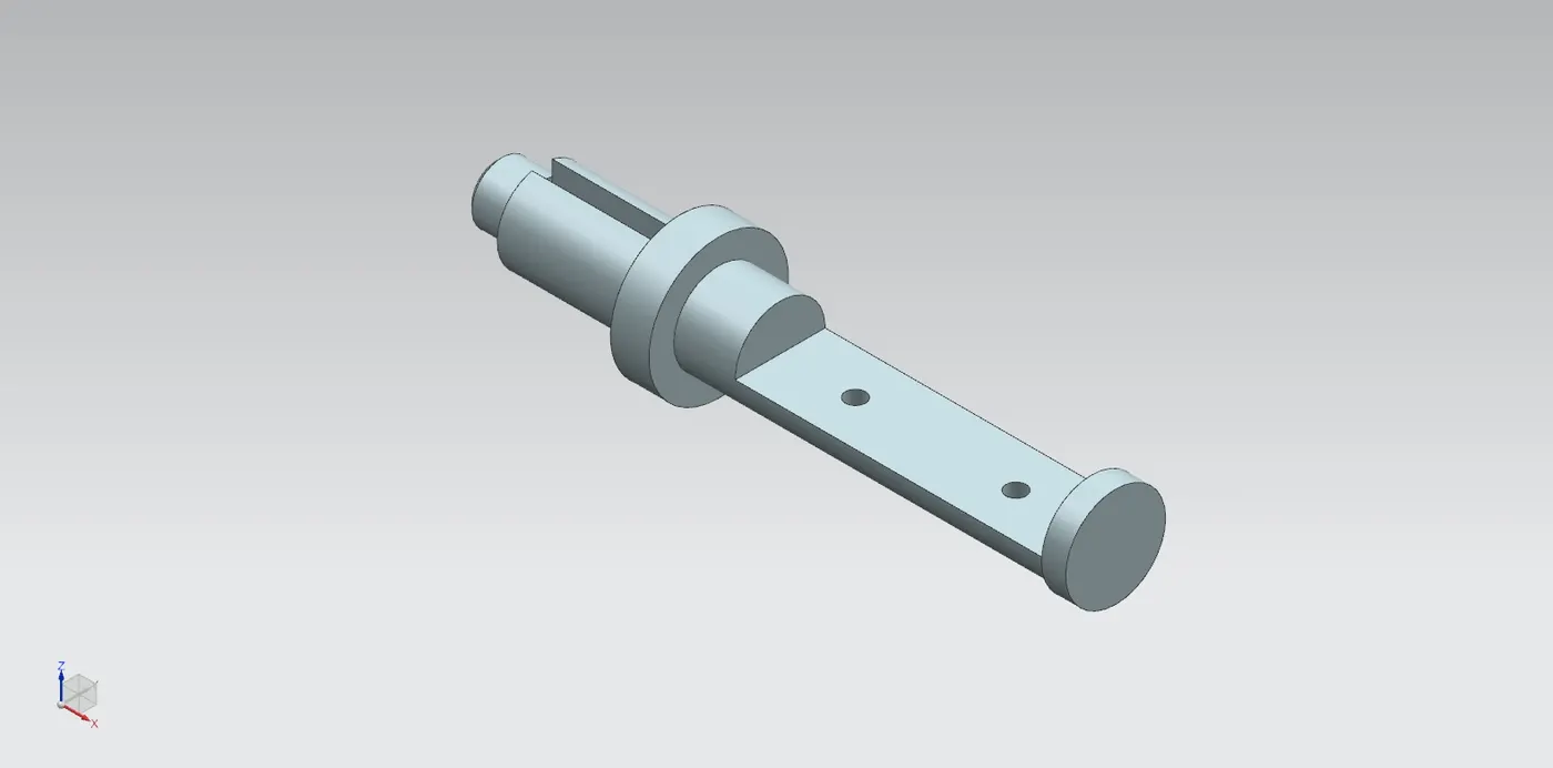
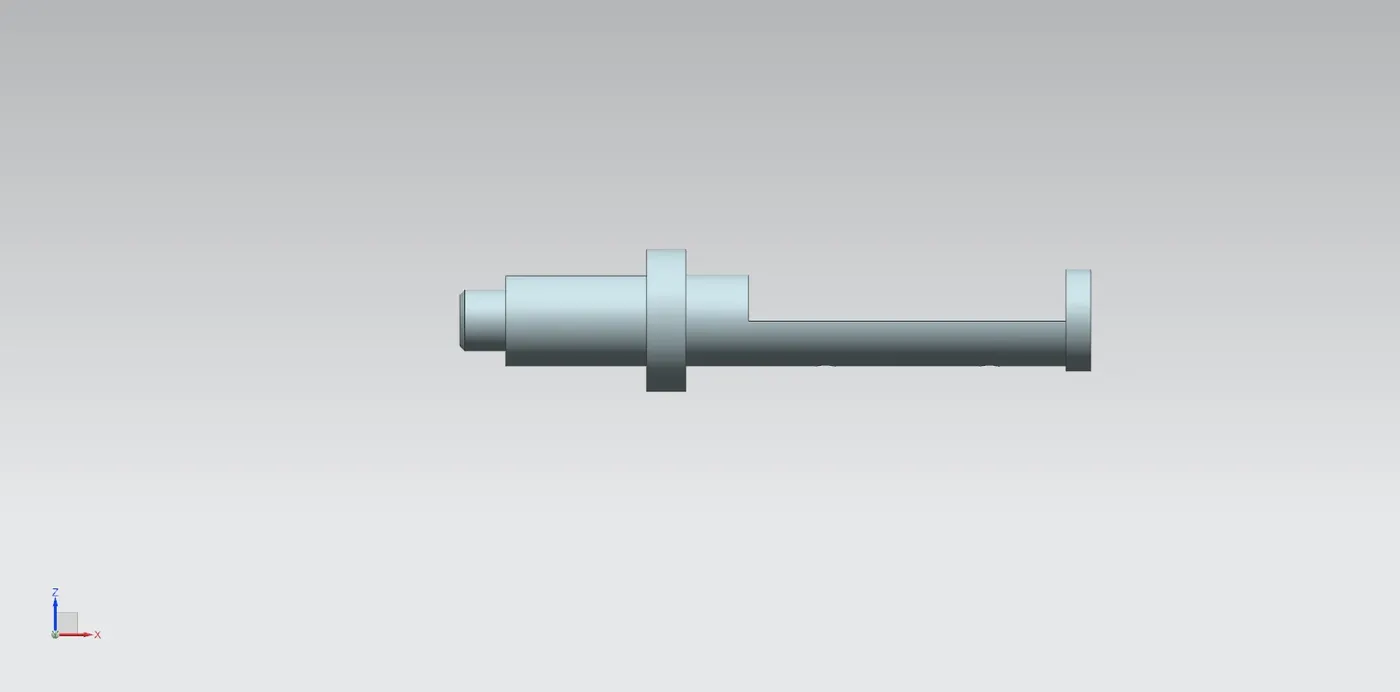
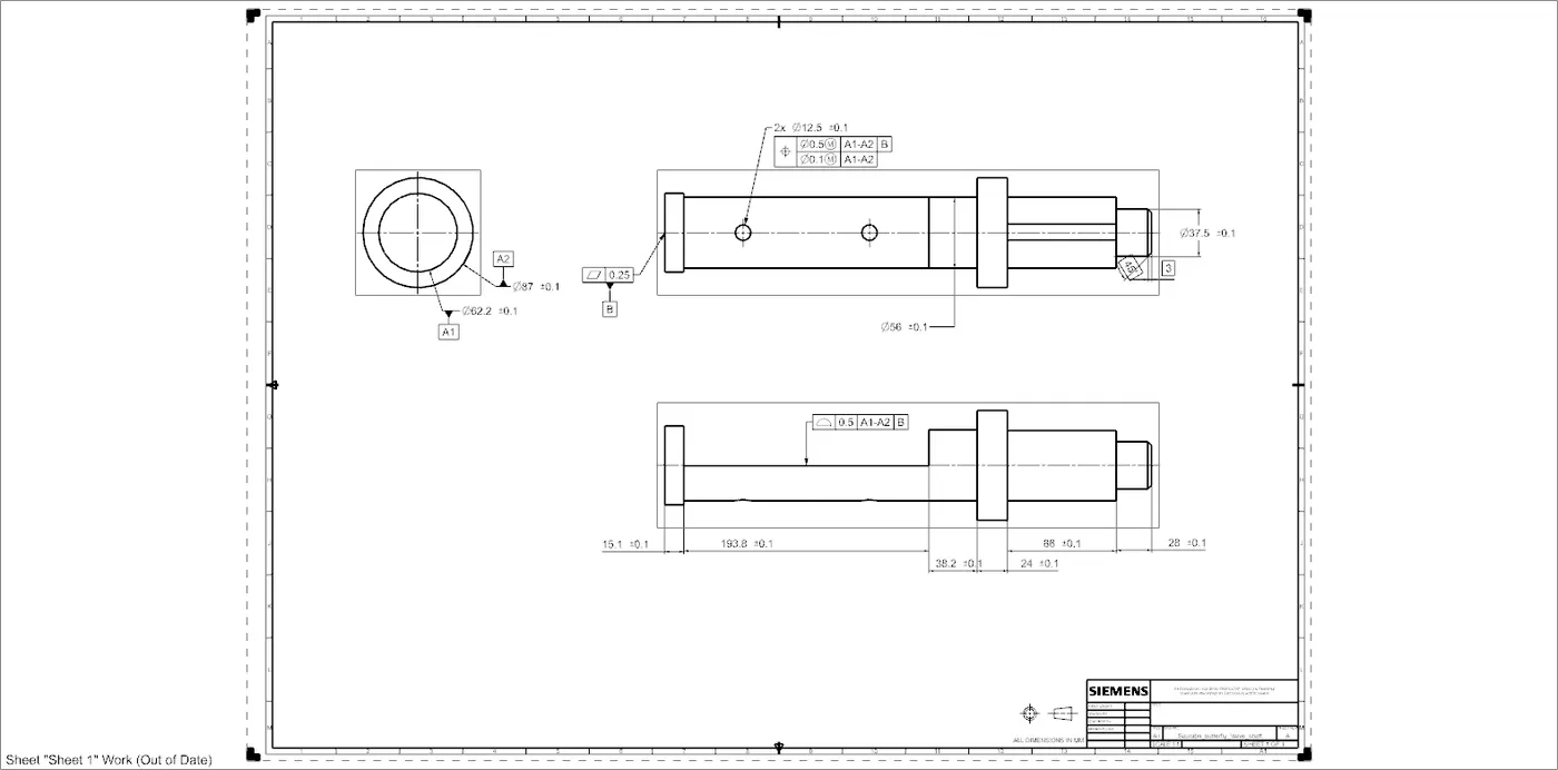
Drafting of shaft:
- A1 size of sheet is used create drawing of shaft.
- Here, only two datums are used as one degree of freedom is required for efficient working of the shaft.
- Datum A1 and A2 is given to the part which comes in contact with the body of butterfly valve.
- Datum B is given to the base of the shaft.
- Different tolerances are given to some features which are important for functioning of the shaft.
3] Disc Plate
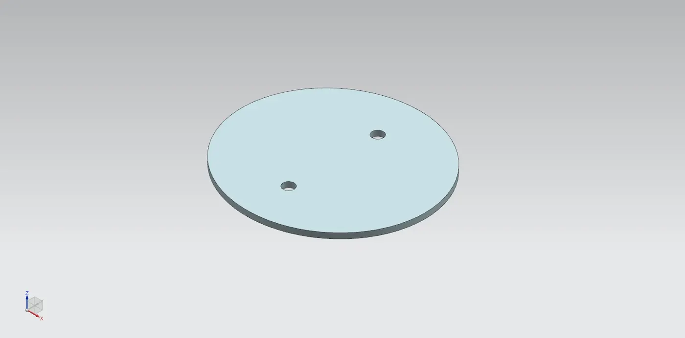
- 2D sketch is created on a plane as per the given dimensions.
- Then, the sketch is Extruded create Disc plate.
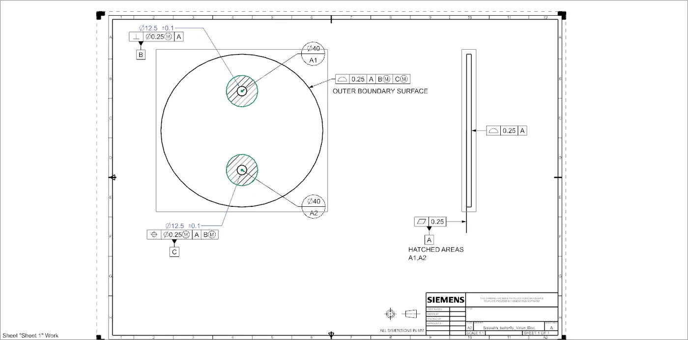
Drafting of Disc plate
- Datum target areas A1 and A2 is given to the side of the disc which is going to come in the contact with shaft.
- This two datum target area A1 and A2 forms datum A.
- Datum B is given to the one hole on the disc plate and Datum C is given to the other hole.
- Then, the tolerances are given to the surface and features of the Disc plate.
4] Retainer
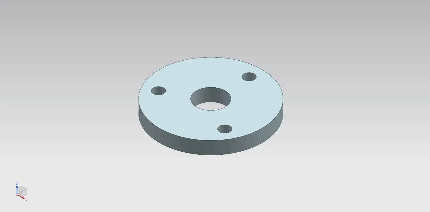
- 2D sketch is drawn on a plane.
- Then the sketch is Extruded to create a Retainer.
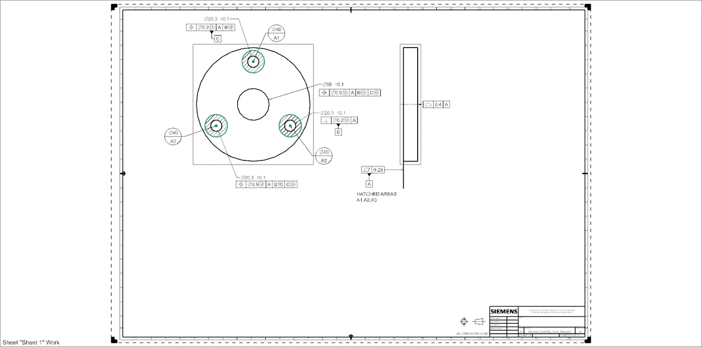
Drafting of Retainer
- After modeling, drafting tool is used to create a drwaing of retainer on A1 size drawing sheet.
- Datum target area A1,A2 and A3 is given to the surface which comes in the contact with the upper surface of body.
- Datum B is applied to the one of the holes of retainer where the screw is inserted.
- Datum C is applied to the other hole.
- Finally, other tolerances are applied to the surfaces and features of retainer.
5] Lever
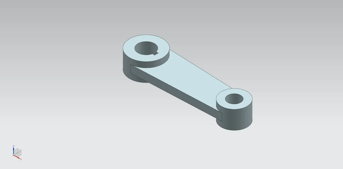
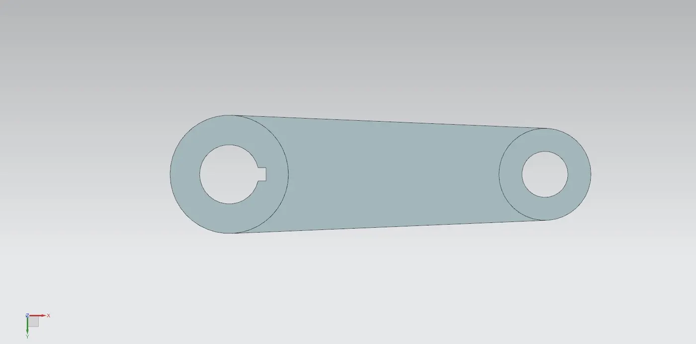
- 2d sketch is created on plane with the provided dimensions.
- sketch is then Extruded to create Lever.
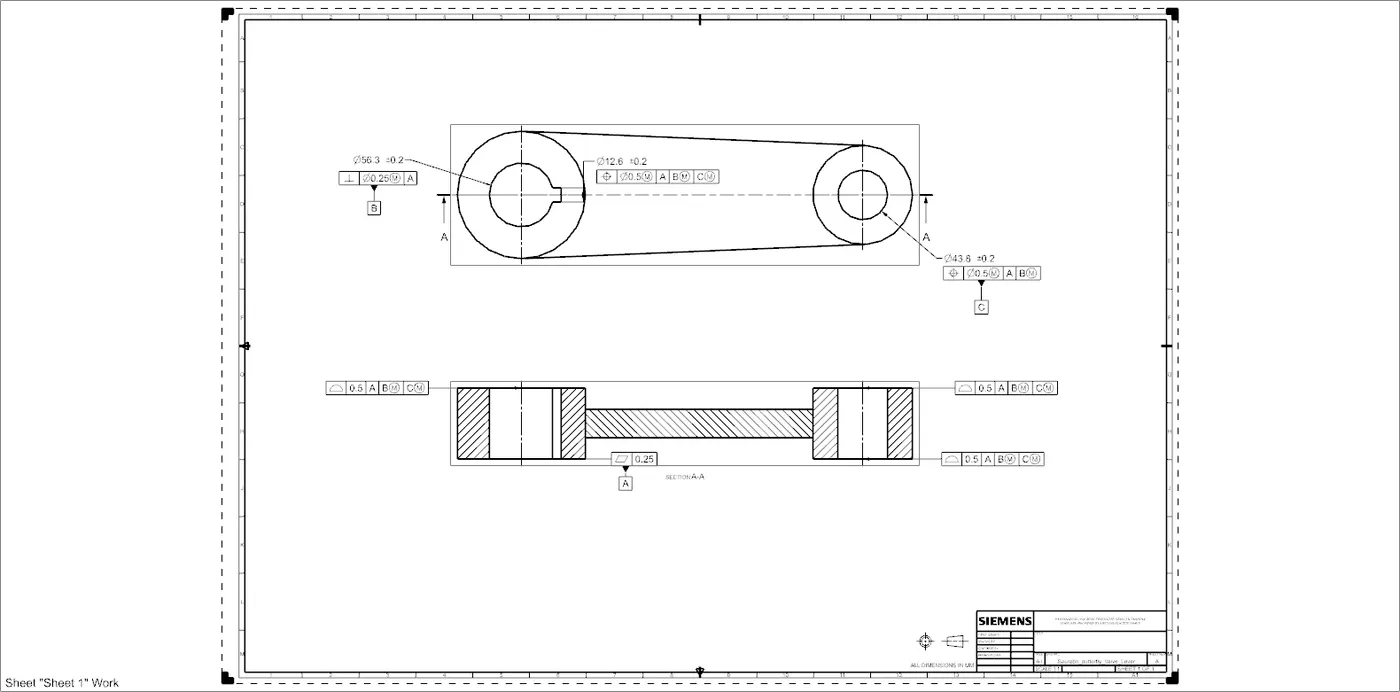
Drafting of Lever
- Datum A is given to bottom surface which comes in contact with retainer.
- Datum B is given to the hole where the bolt is to be inserted.
- Datum C is given to the other hole to complete the constraint the part.
- Finally, other tolerances are applied to the surfaces and features of Lever.
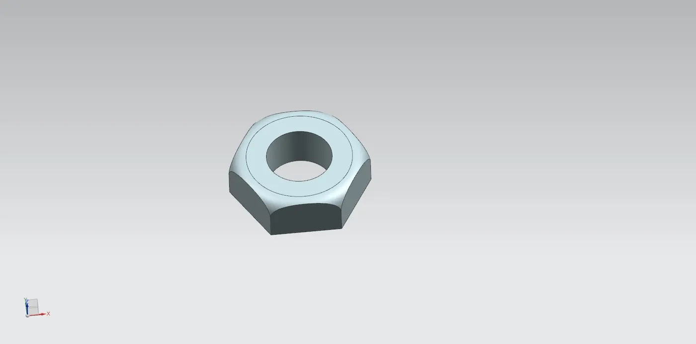
6] Nut
- A hexagon is created on the plane and is then extruded to get desired solid body.
- Another sketch is created on XZ plane, Sketch fillet is used to create a arc which will gives smooth curve to the upper surface of Nut.
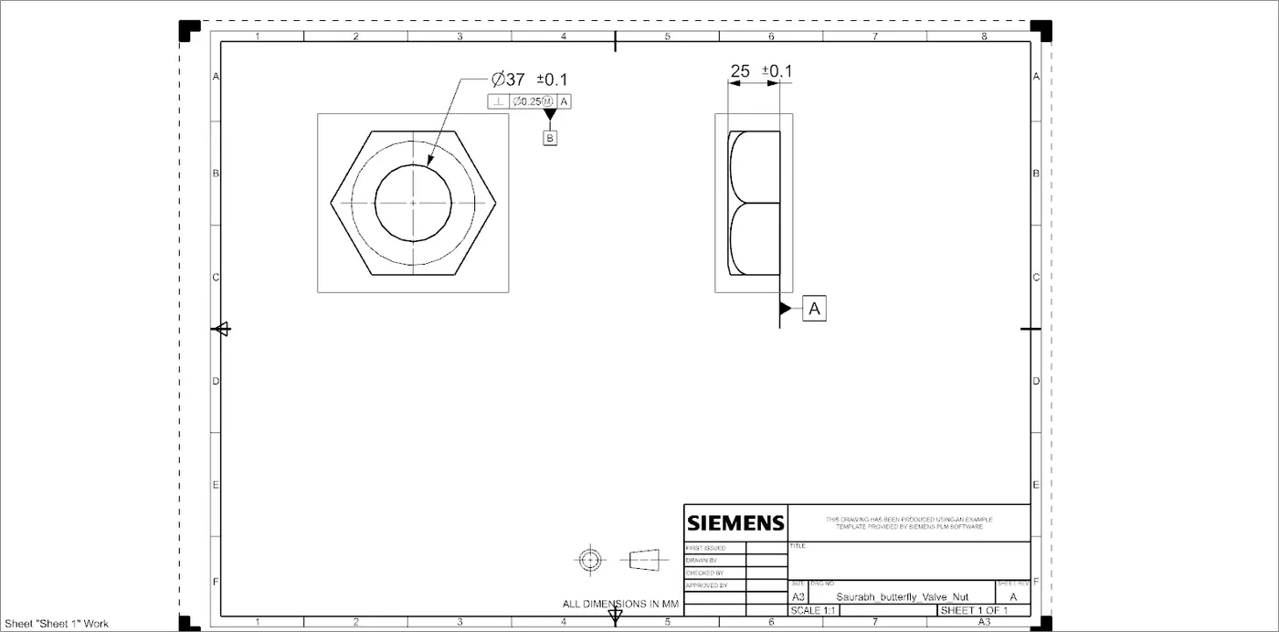
Drafting of Nut
- Datum A is given to the bottom surface of Nut which is going to come in contact with Lever surface.
- Datum B is given to the Hole.
- Finally, other tolerances are given to the surfaces and feature of Nut.
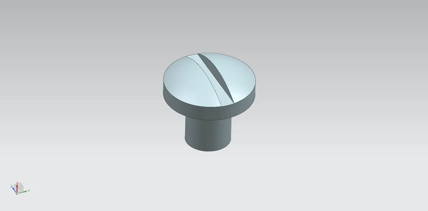
7] Screw
- 2D sketch is created on a plane as per the given dimensions.
- Then, revolve command is used to create a screw and the part is saved.
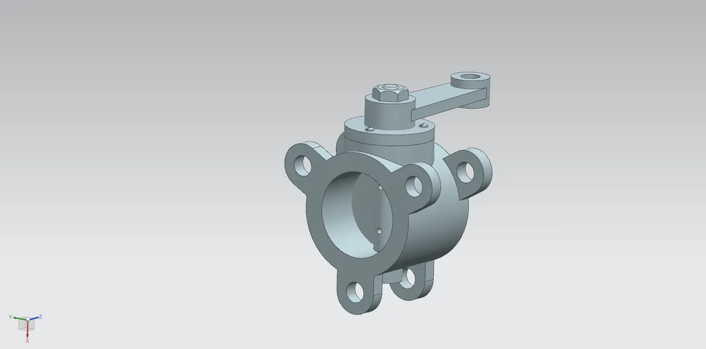
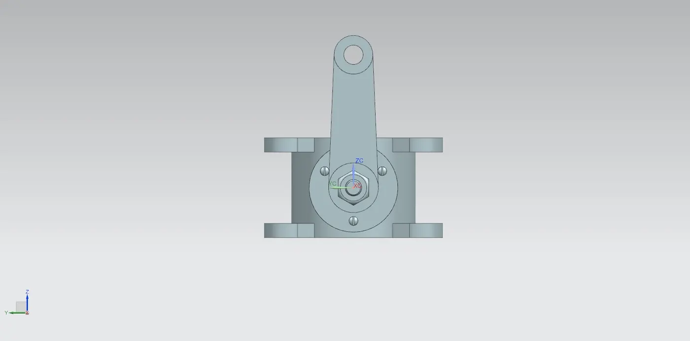
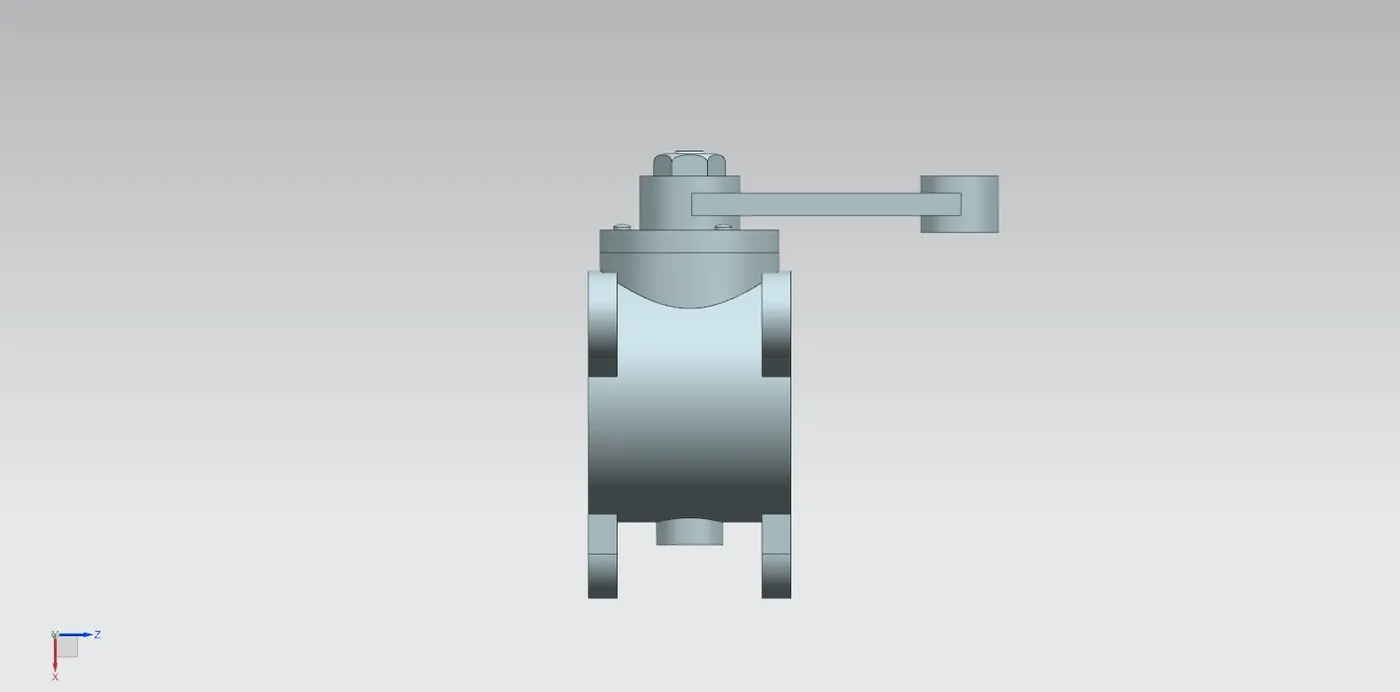
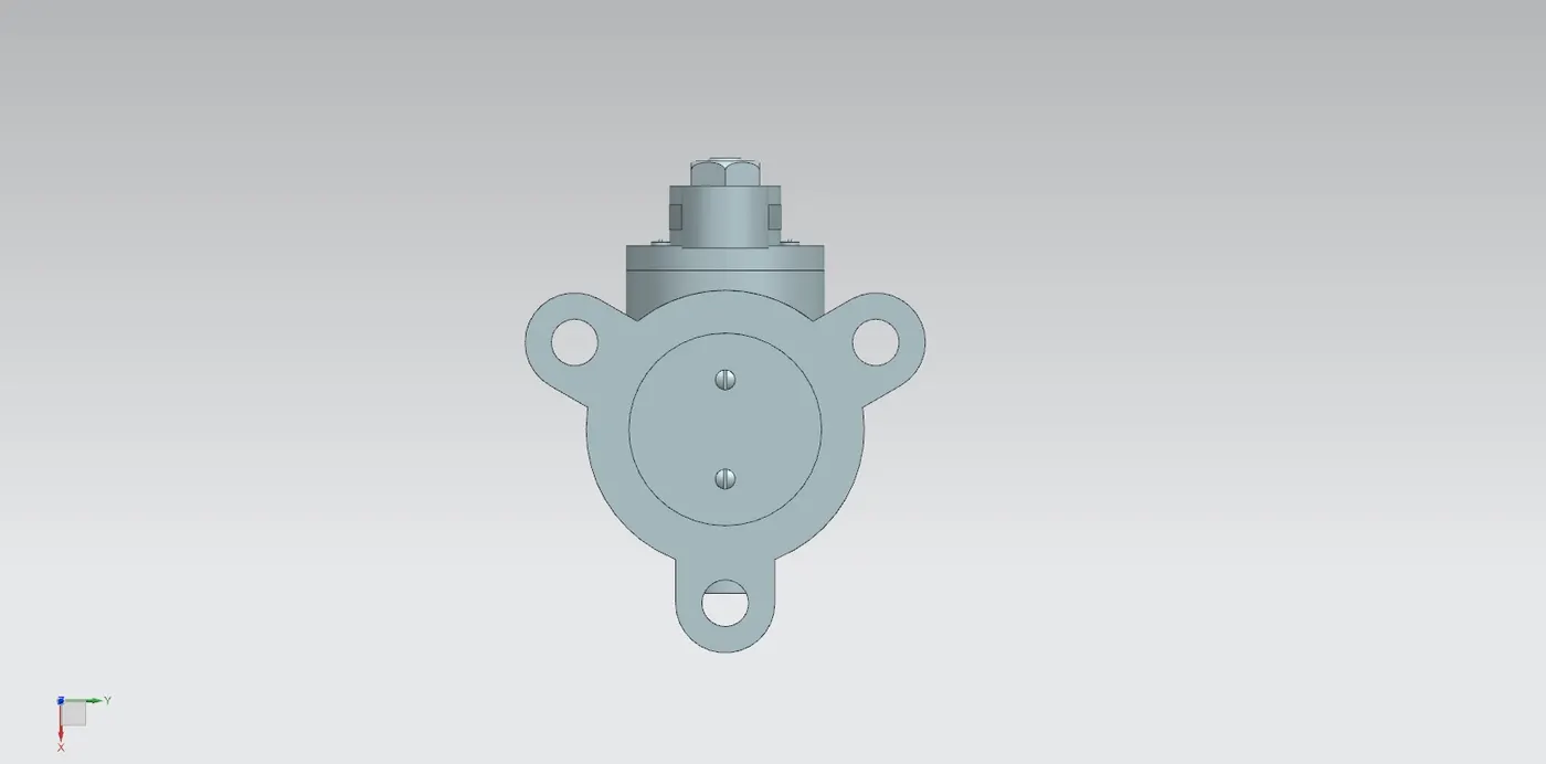
8] Assembly of Butterfly Valve
- Assembly file is opened in NX CAD.
- Above parts are added in the assembly file.
- Now, one by one parts are assembled using Move part command and assembly constraint command.
- Different constraints are used to assemble butterfly valve, such contraints are: Infer Axis, Touch, Align.
- Finally, assembly of BUtterfly vlave is saved in the folder where all the other parts are saved.
Drafting of Assembly
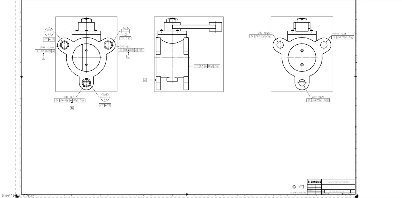
- Datum target area A1,A2 and A3 is given to the ears of the butterfly valve.
- Datum target area A2 and A3 is given with perpendicular tolerance and Position tolerance respectively.
- Sub datum D is given to the thrid ear.
- Finally, other tolerances are given to the surfaces and features of the Butterfly Valve.
Conclusion:-
Designing and Modelling and drafting of different parts and assembly of Butterfly Valve is completed.
Part and Assembly file:-
https://drive.google.com/file/d/1Eu09KkHC8iQjzgJqKUsb7Lt6yBcEBIWR/view?usp=sharing