Design of piston

DESIGN OF PISTON WITH GD&T
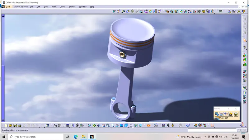
DESIGN BY
RANJITH S
CO-ORDINATE BY
CHIKKAM SHRIKANTH
INDEX
- Abstract
- Introduction
- Objective
- Signification of the simulation
- Application of piston crank arrangement
- Piston
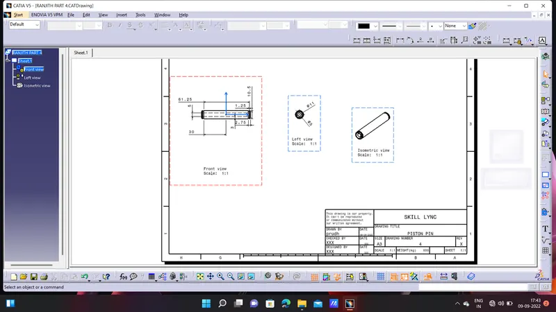
- Wrist
- Connecting Rod
- End cap
10.Crank shaft
11.Assembly
12.Gd&T
13.Conclusion
14.References
DESIGN OF PISTON WITH GD&T
Abstract:
Piston is the part of engine which converts heat and pressure energy liberated by fuel combustion into mechanical works.
Engine piston is the most complex component among the automotives. The design procedure involves determination of various piston dimensions using analytical method under maximum power condition.
Introduction:
Piston is considered to be one of the most important parts in a reciprocating Engine, reciprocating pumps, gas compressors and pneumatic cylinders, among other similar mechanism in which it helps to convert the chemical energy obtained by the combustion of fuel into useful (work) mechanical power.
The purpose of the piston is to provide a means of conveying the expansion of gases to the crankshaft via connecting rod, The piston acts as a movable end of the combustion chamber piston is essentially a cylindrical plug that moves up & down in the cylinder. It is equipped with piston rings to provide a good seal between the cylinder wall.
Objective :
Piston work by transferring the force output of an expanding gas in the cylinder to a crankshaft , which provides rotational momentum to a flywheel. Such a system is known as a reciprocating engine.
The main objective of this work is to investigate and analyze the stress distribution of the piston.
To receive the thrust from the explosion and transmit the force to the crankshaft through the connecting rod.
Signification of the simulation:
The main idea of running a motion analysis is the visualize the movement of the piston reciprocation if the crank rotates at a particular speed.
Usually, the process and calculations are another way round to the reciprocating motion of the piston determines the speed of rotation of the crankshaft.
Application of piston crank arrangement:
1)Reciprocating engine:
The side-crank mechanism which converts straight-line motion to rotary motion and vice-versa, this principle is used in reciprocating engines.
2)Combustion Engines:
Slider-crank mechanism is used in piston-cylinder assembly in combustion engines and converts reciprocating motion into circular motion and vice-versa.
3) Rotary engines:
Fixing the connecting rod in the slider-crank mechanism it can be used to from rotary engines. Rotary engines are used in cars.
4)Oscillating cylinder engine:
Fixing the connecting rod in the slider-crank mechanism it can be used to from oscilating cylinder engines.
5)Hand pump:
Fixing the slider in the slider-crank mechanism it is used to form hand pumps.
Piston:
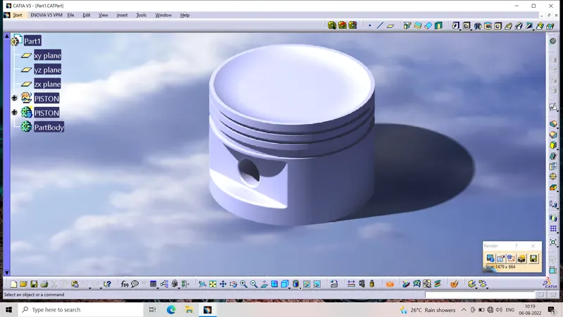
The piston is used to increase the pressure in the combustion chamber and initiate combustion.
A very small indentation is provided in the piston head to have clearance volume in the combustion can take place effectively.
After combustion, the high pressure is generated in the combustion can take place effectively.
After combustion, the high pressure is generated in the combustion chamber puts a downwards pressure on the piston which causes a reciprocating motion.
This reciprocating motion is then transferred to the connecting rod during the modelling process features used are revolution to get the outer cylindrical body and upper indentation, revolved cut is used to get the slots for the piston rings and the linear pattern was used to get the rest of the two slots and using extruded cut the holes were made later for the wrist in sitting the extrusion was made from offsetting from the midplane of the piston and thin extrusion was used to get the slots for the connecting rod movement.
Wrist:
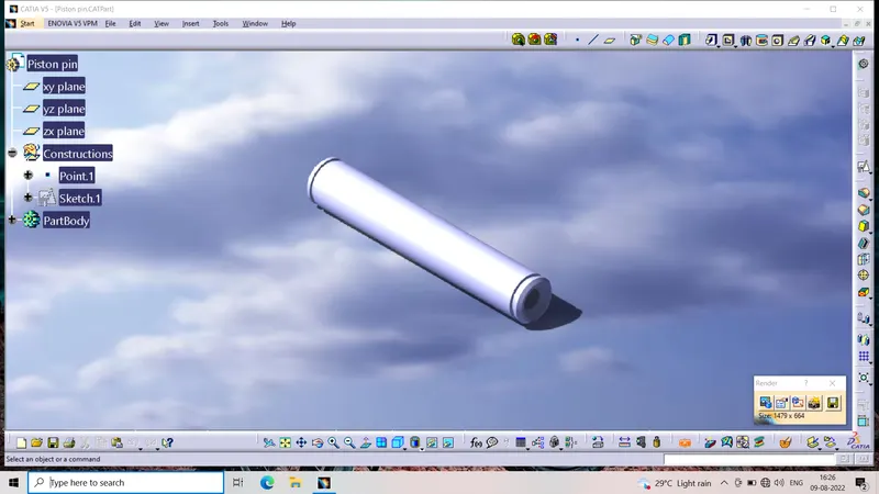
The wrist pin provides a revolute joint between the piston and the connecting rod. The revolute joint is nothing but giving an angular motion DOF to a particular component.
In this case, the revolute joint maximizes the efficiency of the force transfer from the piston to the crankshaft by constraining the motion of the connecting rod, in such a way it has only vertical motion and revolute displacement.
The wrist pin is created using extrusion and chamfer feature.
Connecting Rod:
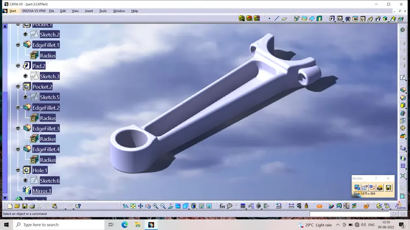
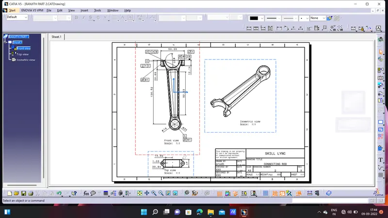
Connecting rod is the body that enables force transfer between the piston and crank shaft.
The connecting rod is constrained on both the sides. It is constrained at the top with the piston by the means of a wrist pin.
The bottom end is fully restrained to the crankshaft, the rod does not have any DOF at the bottom with respect to the crankshaft by the means of an end cap.
The connecting has a combination of reciprocating and rotary motion.
First, the front sketch is made and the extrusion is done in midplane, the cylindrical extrusion is made at the bottom position and then cylindrical holes were made for bolts. Fillets are applied at most of the sharp edges of the connecting rod to prevent stress concertation.
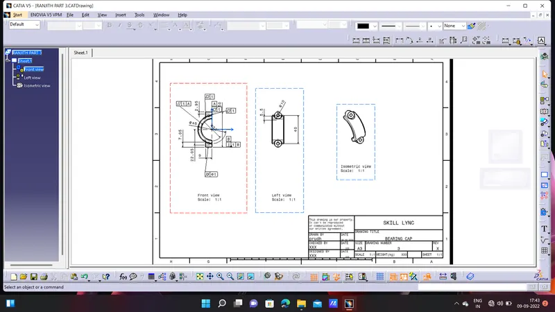
End cap:
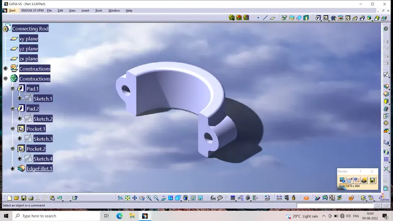
The end cap helps the connecting rod by the means of the bolted joints to stay intact between the lobes of the crankshaft.
This is pretty much like a holding component so that proper motion transmission occurs.
The front sketch is made and the extrusion is done in midplane, the cylindrical extrusion is made and then cylindrical extruded cuts were made for bolts.
Fillets are applied at most of the sharp edges of the connecting rod to prevent stress concertation.
CRANK SHAFT:
The turning motion to the wheels is provided by the crankshaft, which converts the reciprocating motion of the pistons into a rotary motion.
The crankshaft is usually either alloy steel or cast iron. Crankshafts are connected to the pistons by the connecting -rods. The crankshaft has crank throws which are offset from the crank.
The big end of the connecting rod is attached to it. The crank shaft is connected to a flywheel to reduce the torsion vibrations.
ASSEMBLY:
Bottom down approach is used to assemble the various parts for the piston in catia. i.e piston head, connecting rod, wrist pin, crank and end cap etc.
Similarly we imported all components of the piston assembly and assemble them with help of the assemble option.
GD&T:
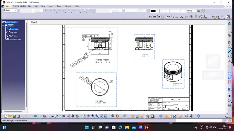
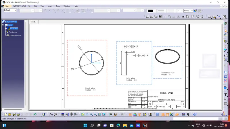
ISO defines GD&T as geometrical products specifications (GPS)—Geometrical tolerancing—Tolerancing of form, orientation, location and run-out.” In short, “geometrical product specifications” refer to the shape, size, and positional relationship of a
product, while “tolerance” means the allowable error.
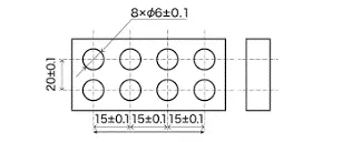
Geometric tolerances are specified using symbols on a drawing. Currently, we have 16 symbols for geometric tolerances, which are categorized according to the tolerance they specify.
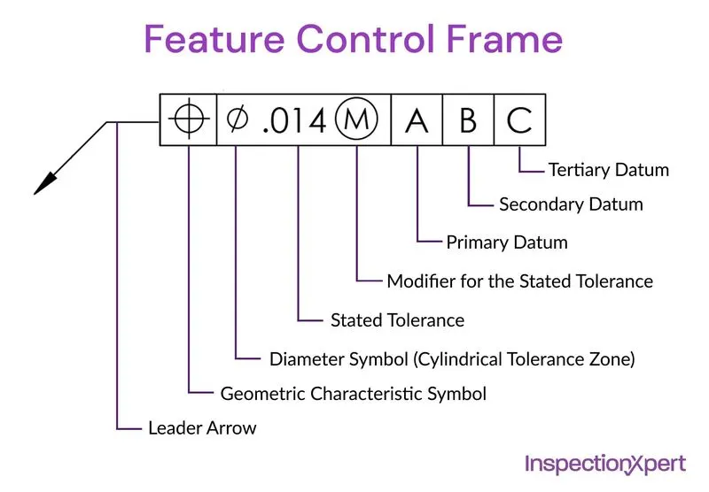
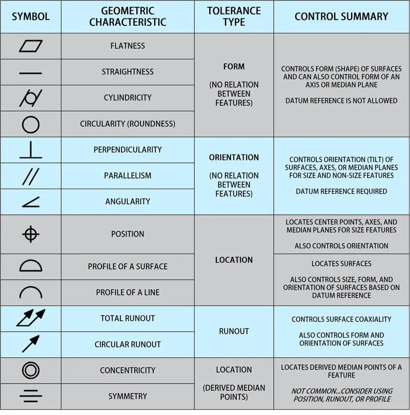
GD&T, a vital part of complex machining, offers a number of major advantages: Saving Money — GD&T enhances design accuracy by allowing for appropriate tolerances that maximize production. For many projects, the process provides extra or bonus tolerances, further increasing cost effectiveness.
CONCLUSION:
The fundamental concepts and design method concerned with single cylinders petrol engine have been studied in this paper the results found by the use of this analytical method are nearly equal to the actual dimensions used now a days.
Hence is provides a fast procedure to design a piston which can be further improved by the use of various software and methods.
The most important part is that very less time is required to design the piston and only a few basic specification of the region.
REFERENCES: