Design of Hood Aston
DESIGN AND MANUFACTURING OF HOOD ASTON
DESIGN BY
RANJITH S
CO-ORDINATE BY
CHIKKAM SHRIKANTH
INDEX
- Abstract
- Introduction
- Parts of hood
- Types of hood support
- Inner panel
- Outer panel
- Emboss
- Mastic sealant
- Hemming
10.Position of hinge &strike
11.Draft Analysis
12.Section Modulus
13.Area of moment inertia
14.Calculation
15.Conclusion
16.References
DESIGN AND MANUFACTURING OF HOOD ASTON
Abstract:
Traffic accidents are terrible scourge that occur in many countries, specially for developing countries where transportation affairs like tangled yarn. Besides functioning as an engine compartment cover, the hood of modern compact SUV can also help to manage the impact energy of a pedestrian’s head in a vehicle -pedestrian impact.
Vehicle safety factors should simultaneously consider occupant and pedestrians safety, given that pedestrians are the third largest category of traffic fatalities. Most pedestrian deaths occur due to traumatic brain injury, resulting from the hard impact of the human head against the vehicle’s stiff hood or windshield.
Therefore, how to design a pedestrian-friendly vehicle and propose a new hood structure is a matter of urgency for minimising pedestrian head injuries.
In this study, three kinds of sandwich hood structures are proposed for reducing pedestrian head injuries, including carbon fibre-reinforced foam and aluminium-reinforced polycarbonates. In assessing the friendliness of vehicle hoods, this study adopts the EEVC/WG17 regulations on head forms for hood tests. The finite element method is used to simulate the impact between the vehicle’s hood and head form impactor. The software used in simulation is LS-DYNA.
The results predicted by the head form-hood tests show that the hood structure with aluminium-reinforced polycarbonate material provides enough absorption capability to protect pedestrians from the impacts of accidents.
It is also stiff enough to keep pedestrian’s heads away from the inner parts of the engine cavity. The analysis models and sandwich materials proposed herein contribute to efforts to design vehicle hood structures and pave the way for developing pedestrian protection technologies.
Introduction:
Bonnet is main component of a car at the front portion. The hood or the bonnet of a car is considered as the frontal BIW enclosure component.
Bonnets are designed to reduce air resistance as the air flows around the car. It is used to decorate the car and add luxurious look. The shape of the bonnet is made aerodynamic in order to minimize the air effect. Bonnet is generally used to access the parts easily such as radiator, engine and many other parts.
In automotive world the weight optimization plays an important role.
In recent years,the work has been done on the bumper and hood design of the vehicle front end to reduce the injuries to the pedestrian vehicle collision. The front portion of the vehicle gets damaged including bonnet or by changing the material. The bonnet is the hinged cover over the engine of motor vehicles that allows access to the engine compartment for maintenance and repair.
Parts of an hood:
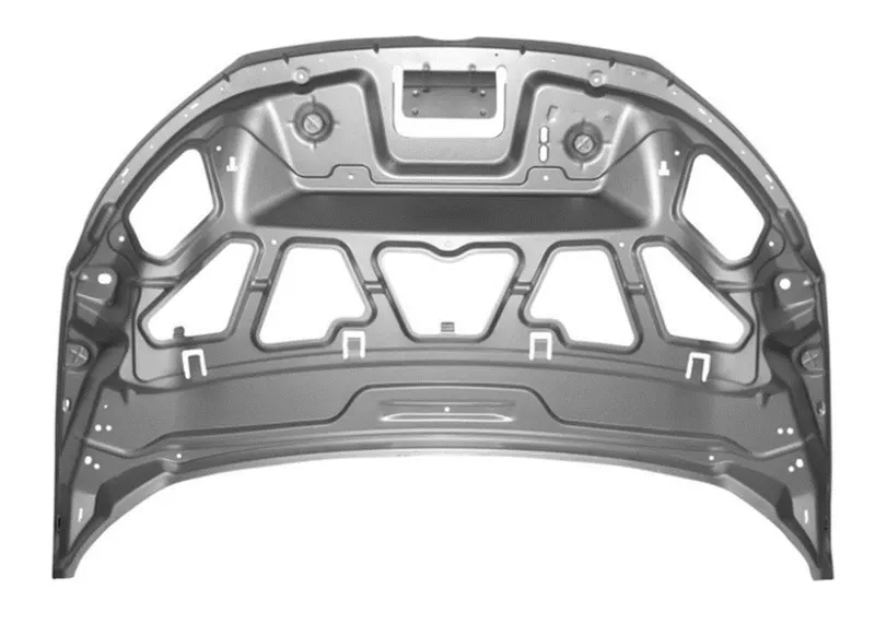
Basically the hood has the inner panel, outer panel and reinforcement (it will provide the strength) and emboss.
Latch and striker mechanism is used to open and close the hood whenever is needed. Latch and hinge is needed some reinforcement for strength.
Types of Hood support:
There are two types of support is there,
1.Gas stay
2.Support rod
Gas stay:
Spring stays are designed to be used on upward lifting doors, once you have opened the door slightly the spring will push the door to the fully open position, Euro fit stock various size springs depending on the door size requirements. This is mostly used for where the car bonnet weight is heavy.
Support rod:
This is widely used in many car, because this very easy and cheap.
In this type we have to lift the hood by ourselves and place the support rod in the space provided either in the hood or engine component. This is mostly used for where the car bonnet weight is small.
Inner panel:
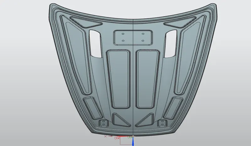
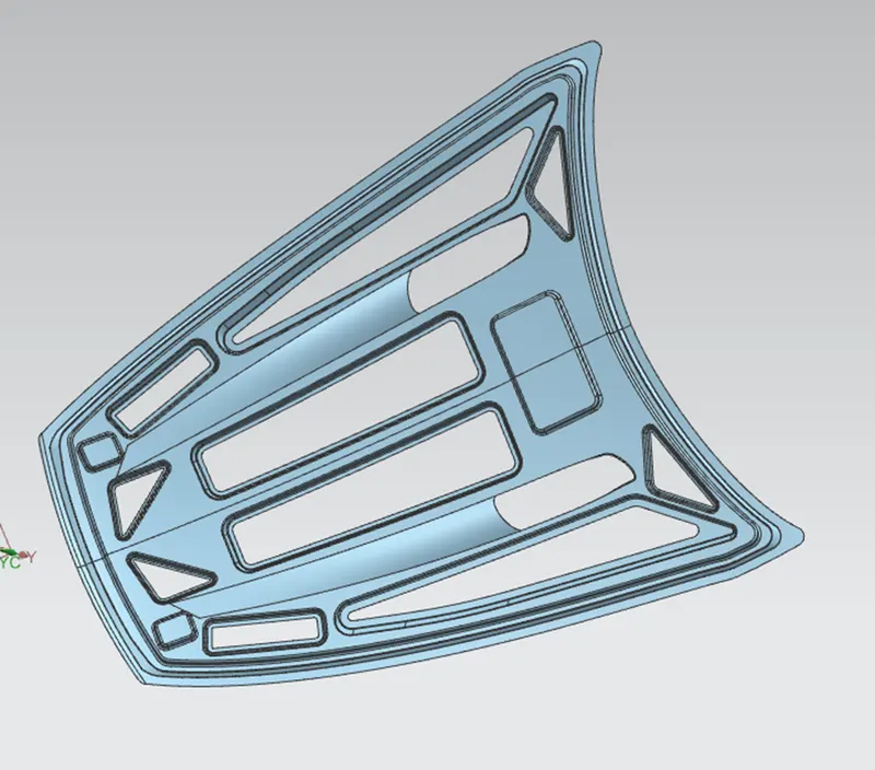
Inner panel supports outer panel. It consists of different embosses and hole at different places. Embosses provide stiffness as well as dissipate energy towards hinges.
To determine the most effective position of hole, the method of modal stiffness is employed.
Inner panel is offset of the parent work surface. Inner panel thickness is 0.65mm.
Outer panel:
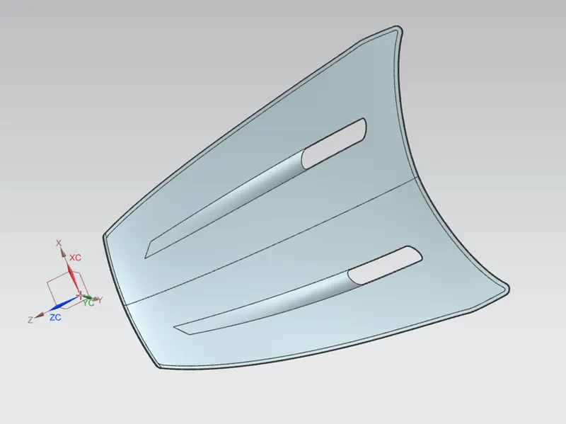
Outer panel is nothing but a outer skin of inner panel. Otherwise called as a cover of inner panel. It is the part, which gives luxurious look to the hood or bonnet. Outer panel and inner panel cannot join by any welding process like spot welding or rivet, which spoil the outer look of a car.
The outer panel is generally extracted model from the prototype design.
Emboss:
The geometry is created based on the master section that was designed above. After performing the intial stages of design, we will provide local embosses to strengthen the component.
The component will be strengthened based on the master section. When a force impacts the hood from the front, it travels in an upward direction.
The component is designed to divert the force away from the passengers into the hinges, as shown in the image below the embosses in the inner panel are made according to the diversion of the load path.
The emboss depth is kept at a maximum of 5mm to be on the safer side so that the part is manufacturable.
To provide strength to the inner panel and to distribute the force produced during the impact with pedestrian or other obstacles to ensure the safety of the passengers. The forces are directed outwards through the embossing path.
Mastic Sealant:
The mastic sealant or the mastic point is an elastic compound that behaves like a rubber.
That mastic points are defined on the hood inner panel where the hood can easily deform.
They help the hood outer panel to come back to its original shape after it gets deformed. The mastic has an influence area of 80mm.
Hemming:
Hemming is the process of joining both the outer and inner panel together.
The hemming process roles and wraps the hood outer panel around the inner panel and holds it tightly together.
Position of Hinge and Striker:
For positioning hinge and striker, we have to place hinge tentatively and take hinge axis point and place position from data taken from the parent car or our own.
The other major functional of the hood is the opening and closing of the hood. This is done with the help of the latch and striker.
To position the latch and striker effectively, we position the hinge and draw the hinge axis.
Now, using the hinge axis as the center we draw a big circle to the position where we need the latch to be placed. Then, we draw a tangent line to the circle at that point and place the latch in that region.
Draft analysis:
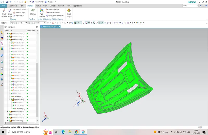
Draft analysis is useful in detecting the negative draft angle of the designed component.
The draft angle which is less than 5degree is not recommendable as per the manufacturing standard of OEM.
Section Modulus:
The section modulus is geometric property of the cross section used for designing beams and flexural members. It does not represent anything physically.
Formula of section modulus:
It may be defined as the ration of total moment resisted by the section to the stress in the extreme fiber which is equal to yield stress.
Therefore,
S=I/Y,
s= section modulus(mm^3)
I= moment of inertia of the section about the bending axis(mm^4)
Y=Distance between the neutral axis and extreme end of the object(mm).
Area moment of inertia:
The area moment of inertia of a beams cross sectional area measures the beam ability to resist bending.
The larger the moment of inertia less will be the bend.
M= Bending moment
I = Area moment of inertia
E = Youngs modulus
R = Radius of gyration
Neutral axis:
When beam is subjected to pure bending the most fibers of the beam are subjected to maximum compression, While the bottom most fiber of the beams are subjected to maximum tension.
Calculation:
Case 1:
The hood which was already created is imported and the section inertia analysis is done.
We have to make sure that the curve obtained is a single/closed curve.
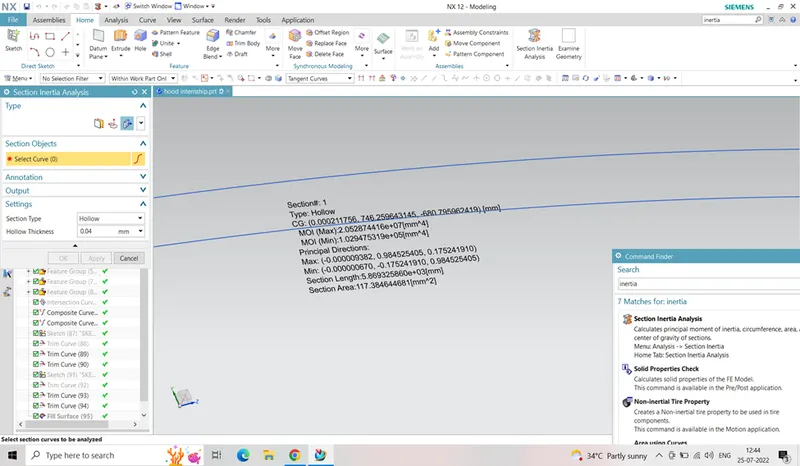
MOI (max)= 2.0528744e+07(mm^4)
MOI (min)= 1.0294753e+05(mm^4)
As per the section modulation equation, S=I/Y
I = MOI(min) value is considered
Y= Total distance / 2
Y= 708.979
S = 102947.55 mm^4 / 708.97
=145.207 mm^3
Case 2:
The hood inner panel’s curve is offset by 0.5mm outwards and selection inertia analysis is done same as case 1 for a closed curve.
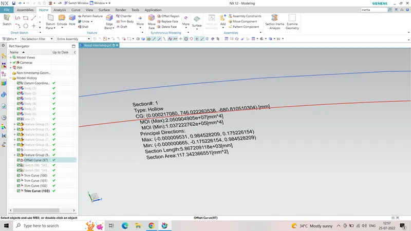
MOI (max) = 2.050904905e+07(mm^4)
MOI (min) = 1.037222762e+05(mm^4)
As per section modulus equation,
S= I/Y
I = MOI (min) value is considered
Y= Total distance/ 2
= 708.979
S= 103722.2762 mm^4 / 708.979
= 146.295 mm^3
Hence when comparing case 1 &case 2,
- The section modulus value of case 2 is higher than the case 1
- As we increase the section area, the moment of inertia & section modulus increases which means strength and load material also increase.
Conclusions:
ISOMETRIC VIEW TOP VIEW
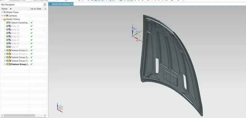
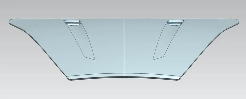
FRONT VIEW RIGHT VIEW
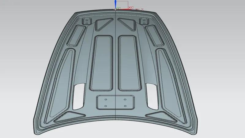
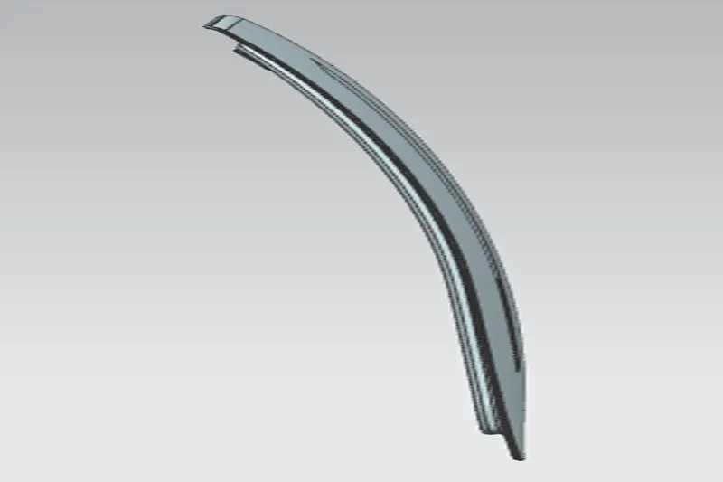
Thus the car hood is designed using the given class A surface and given master sections as well understood the design parameters to be considered for the hood design.
References :
- Huddy, S. G. J. (15 February 2012). "Brent Knoll". Trains, ferries, buses. UK. Retrieved 2 November 2019.
- ^Teng, Tso Liang; Liang, Cho-Chung; Shih, Chien-Jong; Nguyen, Manh-Trung (January 2013). "Design of car hood of sandwich structures for pedestrian safety". Retrieved 2 November 2019.