Design of backdoor
- AIM:Use the provided styling surface to come up with a back door design, use appropriate design methodologies, and provide the necessary reinforcements and embosses.
SOLUTION:
Now we will discuss about geometric dimensioning :
The most common way of showcasing the dimensions of the part are the plus minus signs .It consists of the following :
1. Basic Dimensioning : A numerical value that is used to describe the theoretically exact profile , orientation or location of a feature . Basic dimensions have no tolerance and can not be rejected .
There is a certain standards for the symbols in dimensioning which is used worldwide for easy intrepretation .
Types of geometric dimensioning :
1. Form : This consists of the following : flatness , circularity ,cylinderity , flatness , straightness and it is applicable for only individual features .
2. Profile : It consists of profile for line and profile for surface . It is used for related features .
3. Orientation : It consists of angularity , parallelism and perpendicularity .
4.Location : It consists of position , concentrity , symmetry.
Manufactured items differ in size and dimensions from the original CAD model due to variations in the manufacturing processes. To optimally control and communicate these variations, engineers and manufacturers use a symbolic language called GD&T, short for Geometric Dimensioning and Tolerancing.
With functional assemblies, multi-part products, or parts with complex functionality, it is crucial that all components work well together. All relevant fits and features need to be specified in a way that impacts the manufacturing process and its related investments the least, while still guaranteeing functionality. Tightening tolerances by a factor two can raise the costs twofold or even more, due to higher reject rates and tooling changes. GD&T is the system that allows developers and inspectors to optimize functionality without increasing cost.
For example, a feature standing at 90 degrees to a base surface can be toleranced on its perpendicularity to that surface. This will define two planes spaced apart, that the center plane of the feature must fall within. Or, when drilling a hole, it makes the most sense to tolerance it in terms of alignment to other features.
Engineering drawings need to show the dimensions for all features of a part. Next to the dimensions, a tolerance value needs to be specified with the minimum and maximum acceptable limit. The tolerance is the difference between the minimum and maximum limit. For example, if we have a table that we would accept with a height between 750 mm and 780 mm, the tolerance would be 30 mm.
However, the tolerance for the table implies that we would accept a table that is 750 mm high on one side and 780 mm on the other, or has a waved surface with 30 mm variation. So to appropriately tolerance the product, we need a symbol communicating the design intent of a flat top surface. Therefore we have to include an additional flatness tolerance in addition to the overall height tolerance.
Besides individual tolerances, engineers must take into account system-level effects. For example, when a part comes out with all dimensions at their maximum allowed value, does it still meet overall requirements such as product weight and wall thicknesses? This is called the Maximum Material Condition (MMC), while its counterpart is the Least Material Condition (LMC).
INTRODUCTION:
Types of doors based on working position,
- Top Mounted Door
- Side mounted Door
- Bottom Door
the back door is operated by two types of comodities
1.electrically operated:
2.gas stay powered:
the main purpose of these mechanisims is to open the back door without heavy efforts, because the backdoor have different parts and the weight of the back door is high, so we are not able to open the back door manually, so we introduced these two types comodities. and these also decides the premium of the car, mostly the electrically operated used in premium cars.
1.gas stay powered:
2.electrically operated:
Back Door Assembly:
- Inner panel
- outer panel
- hinge and its reinforcement
- wiper motor reinforcement
- latch & stricker and its reinforcement
- gas stay reinforcement
the major problem in back door is material selection. mostly in past days steel is used, but it makes a very problems the steel parts have heavy weight,so it reduces the fuel economy, insted of steel presently in high end cars aluminium is used, the main objective of aluminium it have less desnser material and its sutaible for complex shapes, and it also gives the thcikness locally because it it done cating, in case of steel we used deep drawing operation. there are some of the advatanges and disadvantages are there
.
so by using of aluminium we can reduce the number of parts and assembly involvement. and it is castly material.
these are the certain tests are done in back door,not only back door all components must pass these tests but different components have different test because of the functionaly.
Different types of Sheetmetal operations are done in the Back Door
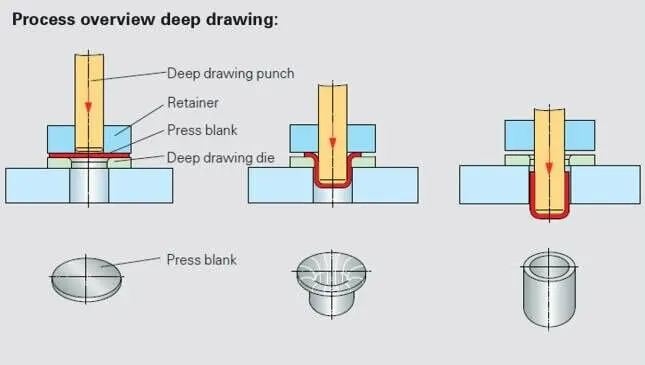
Deep Drawing:
The metal deep drawing process is an effective method of manufacturing of cups, cans and other similar deep drawing products. The deep drawings having two main categories.
- First- stage drawing: The blank shape of metal is placed on the die and contact with the punch. When the metal specimen is flat piece of sheet metal used in forming and finish the product. Initially the punch moves in downward direction. The outer rim of blank is subjected to pure radial drawing (drawing toward in vertical axes) between die and blank metal. The metal become a bend and sliding over die and also stretched between die and punch. The metal in vicinity of punch head and contact with it bend and slide over radii and stretch over punch head.
- Redrawing: The components drawn from first stage again it is redrawn convert into more depth to form a cup shape in the die and punch. The second stage of drawing is called as redrawing.
Embossing:
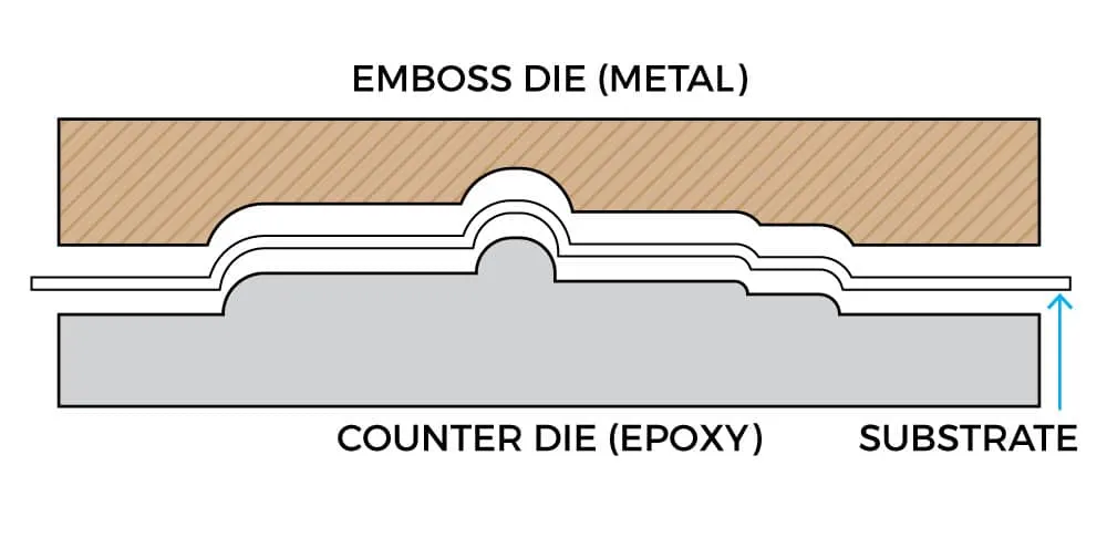
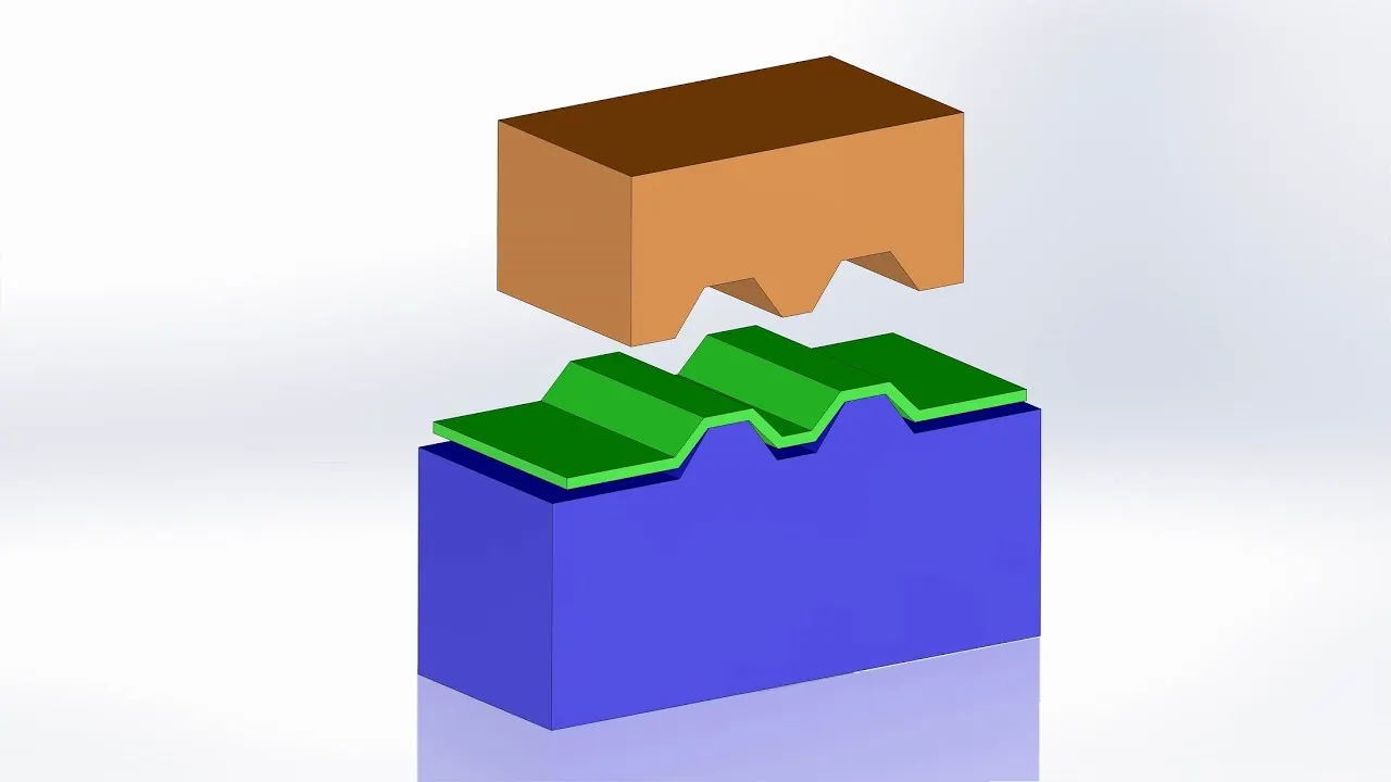
Embossing is a metal forming process for producing raised or sunken designs or relief in sheet materials by means of matched male and female roller dies, theoretically with no change in metal thickness or by-passing sheet or a strip of metal between rolls of the desired pattern. Metal sheet is drawn through the male and female roller dies producing a pattern or design on the metal sheet. Depending on the roller dies used, different patterns can be produced on the metal sheet.
Materials commonly used in the metal embossing process include:
- Aluminum alloys
- Steel alloys
- Zinc
- Copper
- Galvanized steel
- Brass
- Cold rolled steel
Hemming:
Hemming is a forming operation in which the edges of the sheet are folded or folded over another part in order to achieve a tight fit. Normally hemming operations are used to connect parts together, to improve the appearance of a part and to reinforce part edges.
In car part production, hemming is used in assembly as a secondary operation after deep drawing, trimming and flanging operations to join two sheet metal parts (outer and inner) together. Typical parts for this type of assembly are hoods, doors, trunk lids and fenders.
There are various types of hemming operations:
- Conventional die hemming: In conventional die hemming, the flange is folded over the entire length with a hemming tool.
- Roll hemming: In roll hemming, the hemming roller is guided by an industrial robot to form the flange.
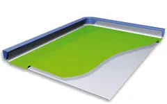
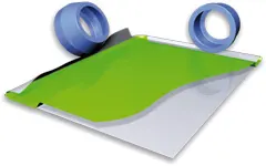
Open Hem: A Hem has a full round feature and a return flange. In open hem bend angle is equal to 180 degrees.
Tear drop Hem: In tear drop hem the bend angle is greater than 180 degrees.
Closed Hem: Hems without any inside radius are called as closed hem. Closed hems are not recommended if the hem geometry is to be painted or if the material used is SST or Aluminium.
Blanking:
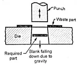
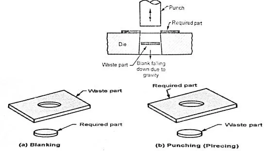
Blanking is a cutting operation of a flat metal sheet and the article punched out is known as blank. Blank is the required product of the operation and the metal left behind is considered as a waste.
Punching:
It is similar to blanking only the main difference is that, the hole is the required product and the material punched out from the hole is considered as a waste.
Now we will work on the following part :
Following are the regions of a car :
1. A Pillar : This takes consideration of the following :
Side Head Room : It is important to have enough side head room so that the driver can have good visibility
Front Pillar Obstacle Angle : This should be taken into account so that the driver can have good visibility.
Glass Stroke : This is the reachibility of the glass from where the person is sitting in the vehicle .If the glass is too close to the person chances of injury during a crash are high . If the A pillar is more inclined , more close the glass is to the person.This also depends on the seating .
2.A Centre Region : This is the region where the steering column is attached as well as cockpit etc . The air vents also come through this region .
3.A pillar Lower region : This is the place where the lower hinges of the door are mounted .
4.Sill : This is the bottom most part of the car and keeps the harness .
5.Front Door : There are conditions in which the hinge axis of the door is inclined :
a. Forward Inclination : This is the condition in which the hinge axis is inclined wrt to the car vertical axis
b.Vertical Condition : This is condition in which the hinge axis is parallel to the vertical car axis and the amount of force required to open and close the door are similar .
c.Inward Inclination : In this condition the dead weight acts towards closing condition as the majority of the weight is inclined downwards .
d.Outward Inclination : In this condition the dead weight acts outward during the opening condition and an additional amount is required while openining.
6.Center Pillar or B Pillar : This is the pillar which is joining the upper and bottom of the car .This pillar is the region which holds the striker that enables the closing of the door.
Sometimes checklinks are installed on the a pillar so that the door is opened in intervals so that the user does not have to apply a lot of efforts in opening the door.
The assembly sequence for aluminium is given as below :
The inner panel is going to be a single part whereas the outer panel can be split into two or three parts .The outer panel is usually a casted part .Aluminium has the advantage of variable thickness and helps to reduce weight but it is expensive to produce parts of aluminium
The various load cases on the door are :
1.Bend Test
2.Torsion Test
3.Abuse Test
4.Endurance Test
In order to have good strength it is important to have a y emboss so that there is force distribution done properly.
The following will be part of the backdoor :
1.Backdoor inner
2.Backdoor outer
3.Wiper motor reinforcement
4.Reinforcements
5.Hemming so that we can apply sealant inside the small volume.
Now we will do some clean up of the given class A surface in order to create a good class B and Class C surface :
BACK DOOR UPPER AND LOWER PANEL:
INNER PANEL:
UPPER HEMMING PANNEL:
LOWER HEMMING:
GAS STAYS:
HING REINFOCEMENT:
WIPERS:
DRAFT ANALYSIS:
TOP VIEW:
SIDE VIEW:
ISOMETRIC VIEW:
CONCLUSION:
The back door outer and inner panel were designed with the help of the styling surface along the tooling direction.and
Draft analysis was performed on the inner panel and All the reinforcements were designed and placed at appropriate positions.