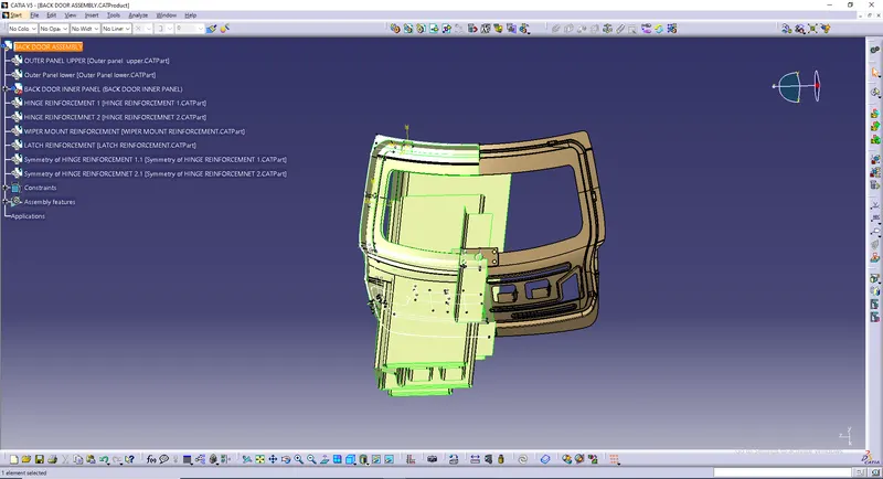
Design of backdoor
BACK DOOR:
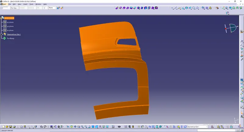
This is the IGS file given where we have to design.
WIPER MOUNT:
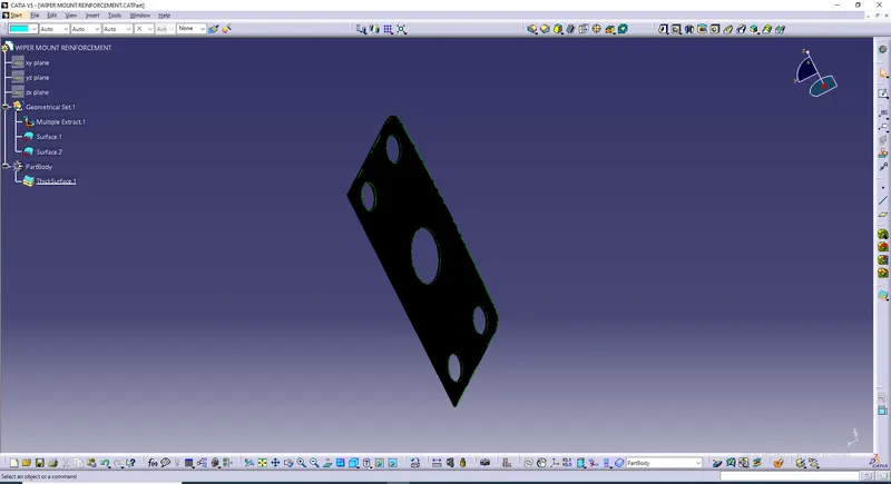
- Intially we have to create Wiper Mount Reinfocement.
- For wiper mount, surface 1 & surface 2 has to be taken.
- Multiple Extract both the surfaces.
- Make it as a solid body.
OUTER PANEL LOWER PART:
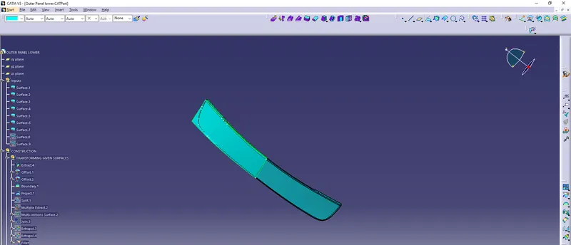
- Take surface 1 to surface 7 to create outer panel Lower Part.
- Insert a Geometrical Set Constructions.
- Insert a geometrical set inside constructions Transforming Given Surfaces.
TRANSFORMING GIVEN SURFACES:
- Extract Surface.6\Face.7
- Offset surface 6 for 2mm & deviation 1mm.
- Offset the ofset1for 2mm.
- Insert a Boundary for Extracted surface.
- Project boundary1 with support offset2.
- Split offset2 with projection 1.
- Multiple Extract surface.4\face.9 & surface.2\face.10
- Insert Multi Section Surface for multiple extract surface & support given as extract 5 & extract6 & tnget continuity.
- Join multi section surface & multiple extract.2
- Extrapolate split1 at alength of 2mm.
- Extrapolate join3 at a length of 10mm.
- Select a Bi-tangent fillet & apply fillets for Extrapolate 3 & 4.
HEMMING:
- Insert a geometrical set Hemming under construction.
- Apply a offset of filleted face for 2.65mm
- Apply a boundary for offset.3\edge.18, Limit 1 as boundary.2 & Limit 2 as fillet\vertex.2
- Insert a parallel curve for boundary2 & support as offset3 for 7.325mm
- Project parallel2 & support as offset3
- Split offset3 with projection2.
- Insert a point.
- Draw a sketch.
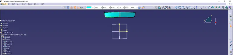
- Extrude the sketch.
- Split the split2 with extrude1.
- Join split.3
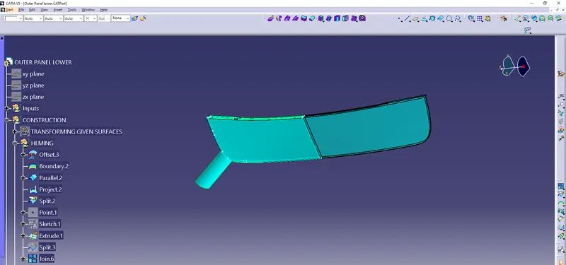
C FACE:
- Insert a geometrical set C Face under construction.
- Multiple Extract fillet\edge.31 to fillet\ edge.37
- Sweep with reference surface, guide curve as Multiple extract.4 & reference surface as fillet for 3mm & 90deg.
- Extrapolate filletfor 10mm.
- Trim sweep2 & extrapolate 5.
- Trim trim 1 join 6 (present in hemming)
- Edge fillet trim2 for 1.325mm.
- Edge fillet, edge fillet1 for 1.15mm.
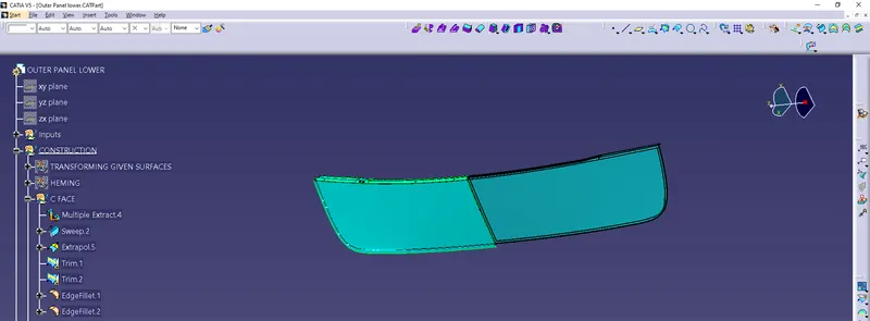
FINAL:
- Insert a geometrical set Final under construction.
- Extrapolate edge fillet2 for 10mm.
- Split extrapolate6 with xy plane.
- Symmetry split4 with xy plane.
- Join split4 & symmetry1.
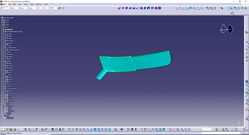
OUTER PANEL UPPER PART:
- Insert a Geometrical Set Construction
- Insert another geometrical set Transforming Inputs.
TRANSFORMING INPUTS:
- Extract surface.13\face.1
- Multiple Extract surface.11\face.2 & surface.11\face.3
- Extract surface.26\face.4
- Multiple Extract surface.7\face.7 & surface.20\face.8
- Extract surface.3\face.9
- Extract surfce.14\face.10
- Extract surface.18\face.11
- Extract surface.27\face.12
- Extrapolate extract.1, extract.2 & multiple extract.1 for 6mm
- Join surface1 to surface30.
- Extrapolate multiple extract.3, extract.3,extract.4,extract.5
- Extrapolate , extrapolate.7 for 5mm
- Extrapolate ,extract.6 for 9mm
- Multiple Extract join.1\face.13 & join.1\face.14
- Extrapolate, multiple extract.4
- Insert Bi-tangent fillet for extrapolate.1 & extrapolate.2 for 5mm
- Insert Bi-tangent fillet for fillet.1 & extrapolate.3 for 5mm
- Insert Bi-tangent fillet for extrapolate.10 & extrapolate.4 for 5mm
- Insert Bi-tangent fillet for fillet.3 & extrapolate.5 for 5mm
- Insert Bi-tangent fillet for fillet.4 & extrapolate.6 for 5mm
- Trim fillet.5 & extrapolate.8
- Edge fillet trim2 for 5mm
- Insert Bi-tangent fillet extrapolate.9 & edge fillet.2 for 5mm
- Multi Section Surface, section fillet.6\edge.20 , fillet.2\edge.21 & support fillet.6, fillet.2 respectively in tangent continuity
- Join fillet.2, multi section surface.1 & fillet.6
- Multiple extract join.1\face.15 & join.1\face.16
- Multi Section Surface, section extract.7, multiple extract.6 & support extract.8,extract.9 respectively in tangent continuity
- Join multiple extract.5 & multiple section surface.2
- Extrapolate join.3 for 10mm
- Trim join.2 & extrapolate.11
- Edge fillet trim3
- Insert a point
- Insert a boundary surface edge fillet\edge.30, Limit 1 fillet\vertex.1 Limit 2 fillet\vertex.2
- Insert a corner for Element 1 is extract.10 & Element 2 is extract.11 for 30mm
- Trim boundary.1 & corner.1
- curve smooth trim4
- Split fillet with curve smooth1
- Split extrapolate.13 with spline.8
- Extrapolate split1 for 1mm
- Extract extrapolate.13\edge.205
- Join extrapolate.13
- Join extrpolate.13\face.85 & extrapolate.13\face86
- Insert a parallel curve multiextract.9 & supportjoin.16 for 2mm
- Curve smooth parallel curve10
- Split join.16 with curve smooth9
- Join, join15 & split20
- Extrapolate join.17for 3mm
- Extrapolate , extrapolate.30 for 3mm
- Insert 2 points
- Insert a spline for those 2 points
- Fill extrapolate.31\edge.237 with support extrapolate.31 , extrapolate.31\edge.238, Extrapolate.31\edge.239 &spline.37
- Join fill.5 & extrapolate.31
- Extrapolate join.18 for 3mm
- Fill extrapolate.32\edge.245,extrapolate.32\edge.246, extrapolate.32\edge.247
- Join fill.6 & extrapolate.32
- Extrapolate join.19 for 2mm
- Insert a spline between extrapolate.35\vertex.129 & extrpolate.35\vertex.130
- Fill spline.56, extrapolate.35\edge.332 ,extrapolate.35\edge.333, & extrapolate.35\edge.334 with support extrapolate.35 for all3 except spline.56 in tangent continuity
- Join fill.8 & extrapolate.35
- Extrapolate join.25 for 2mm
- Extrapolate , extrapolate.36 for 0.5mm
- Extrapolate, extrapolate.37 for 0.5mm
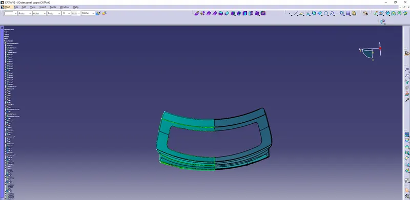
HEMMING:
- Insert a geometrical set under conastruction Hemming.
- Offset the split1 surface for 2.65mm
- Insert a boundary for offset.1, Limit1 as offset.1\vertex.3, Limit2 as offset.1\vertex.5
- Insert a parallel curve , curve as boundary2 & support as offset.1
- Curve smooth parallel1
- Project curve smooth3 & support as offset1
- Split offset1 with project1
- Join split2
- Draw a sketch.
- Extrude the sketch.
- Split join4 with extrude1.
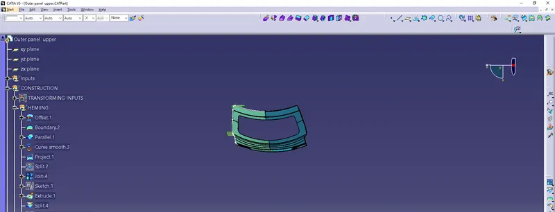
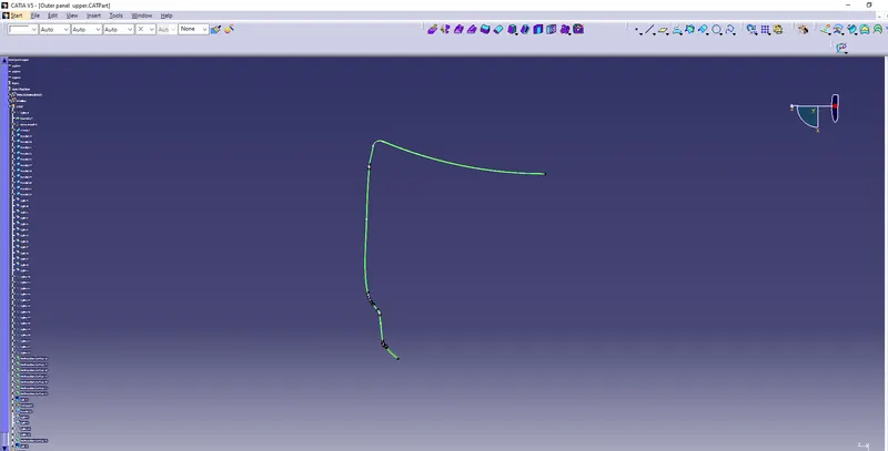
C FACE:
- Insert a geometrical set C Face under construction.
- Insert a boundary surface edgae as split.7\edge.82, Limit1 as split.7\vertex.30, Limit2 as split.7\vertex.31
- Curve smooth the boundary.
- Sweep with reference surface, Guide curve as curve smooth.8 & reference surface as split.7 for 4mm & 90deg
- Insert 11 parallel curves.
- Insert 11 splits for those parallel curves.
- Split , split.36 with parallel curve.30
- Split , split.39 with parallel curve.31
- Split , split.39 with parallel curve.32
- Insert 14 splines.
- Insert 7 multi section surface
- Join all multi section surfsce
- Extrapolate join.21 for 2mm
- Insert a parallel curve for Extrapolate.34\Edge.30 & spport as extrapolate.34
- Split extrapolate.34 with parallel curve.33
- Split extrapolate.34 with parallel curve.34
- Insert 2 splines.
- Insert a multi section surface.
- Join split.42, split.43 & multi section surfsce.25
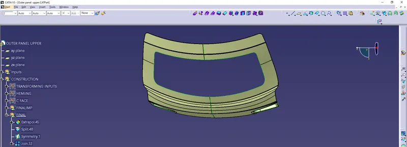
FINAL:
- Extrapolate split.47 for 5.5mm
- Split the extapolated surface with xy plane
- Symmetry the splitted surface with xy plane.
- Join split.48 with symmetry.1
OUTER PANEL UPPER PART SOLID PART:

LATCH REINFORCEMENT:
- Insert a Geometrical Set Construction.
- Multiple Extract surface.1\ face.1 & surface.2\face.2
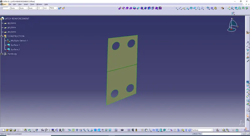
LATCH REINFORCEMENT SOLID PART:
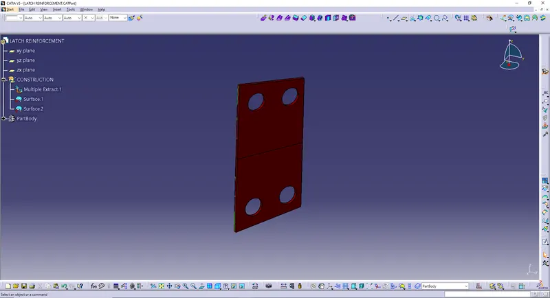
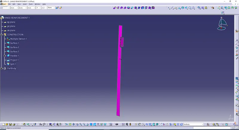
HINGE REINFORCEMENT1:
- Insert a Geometrical Set Construction.
- Multiple Extract surface.1\ face.1, surface.2\face.2 & surface.3\face.3
- Insert a parallel curve, curve as multiple extract.1\edge.1 & support as multiple extract.1 for 303mm
- Project parallel curve.1 & support as multiple extract.1
- Split multiple extract.1 with parallel curve.1
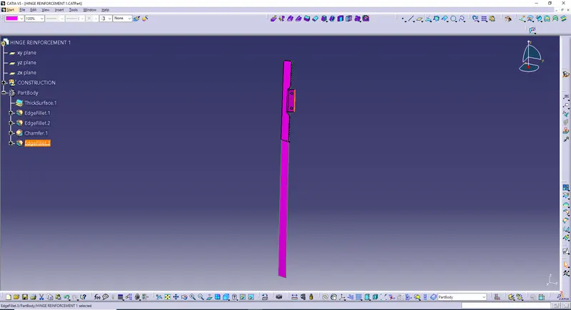
HINGE REINFORCEMENT1 SOLID PART:
- Intially thicken the surface for 1.5mm
- Insert 2 edge fillets for 3mm & 7mm respectively.
- Insert a chamfer, mode as Length1\Angle for 1mm & 45deg & object to chamfer edge fillet.2\edge.7
- Insert another edge fillet for 0.5mm.
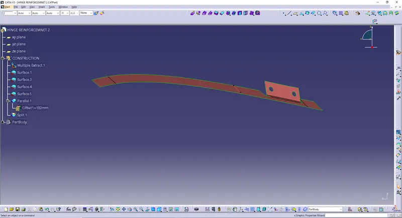
HINGE REINFORCEMENT2:
- Insert a Geometrical Set Construction.
- Multiple Extract surface.1\ face.1, surface.3\face.3, surface.4\face4 & surface.5\face.5
- Insert a parallel curve, curve as multiple extract.1\edge.1 & support as multiple extract.1 for 182mm
- Split multiple extract.1 with parallel curve.1
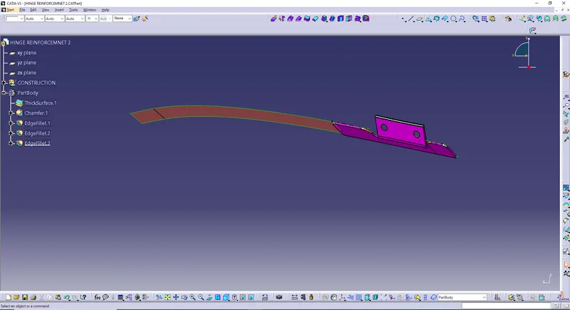
HINGE REINFORCEMENT1 SOLID PART:
- Intially thicken the surface for 1.5mm
- Insert a chamfer, mode as Length1\Angle for 1mm & 45deg & object to thick surface.1\edge.1
- Insert 3 edge fillets for 0.5mm, 3mm & 7mm respectively.
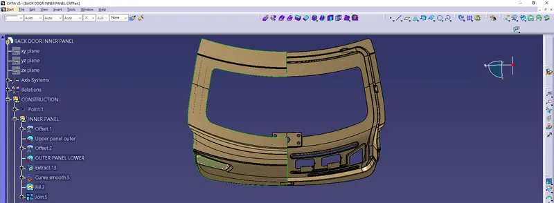
BACK DOOR INNER PANEL:
- Insert a Geometrical Set Construction.
- Insert a point under construction.
- Insert a geometrical set under construction Inner Panel.
INNER PANEL:
- Offset Upper Panel Outer for 1.7mm.
- Offset Lower Panel Outer for 1.7mm.
- Extract offset.1\edge.42
- Curve smooth the extracted surface.
- Fill the curve smooth surrface.
- Join filled surface & offset.1
SEALING FLANGES:
- Insert a geometrical set Sealing Flanges under construction.
- Offset, surface Extract.26 for 25mm.
- Offset, surface Multiple Extract.21 for 25mm.
- Extract join.5\face.21
- Surface Untrim the extracted surface
- Offset the surface untrimmed surface for 68mm.
- Offset the surface extract.28 for34mm.
- Insert a geometrical set Flanges Creation under Sealing Flanges.
- Insert a parallel curve, curve as offset.9\edge.313 & support as offset.9 for 40mm
- Insert a parallel curve, curve as parallel curve.58 & support as offset.9 for 30mm
- Insert a parallel curve, curve as multiple extract.22 & support as offset.10 for 45mm
- Insert a curve smooth for parallel.60
- Insert a parallel curve, curve as curve smooth.10 & support as offset.10 for 30mm
- Insert a curve smooth for parallel.61
- Offset, surface offset.11 for 2mm
- Surface Untrim offset.13
- Insert a parallel curve, curve as surface untrim.4\edge.316 & support as surface untrim.4 for 30mm
- Insert a parallel curve, curve as parallel curve.62 & support as surface untrim.4 for 30mm
- Draw a sketch.
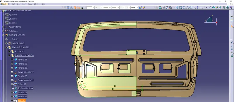
- Extrude the sketch.
- Split offset.9 with parallel curve.58 & parallel curve.59
- Split offset.10 with curve smooth.10 & curve smooth.11
- Split surface untrim.4 with parallel curve.62 & parallel curve.63
- Split offset.12 with extract.32 & extract.33
- Insert a parallel curve, curve as split.76\edge.317 & support as split.76 for 113mm
- Insert a parallel curve, curve as split.77\edge.318 & support as split.77 for 7mm
- Split, split.76 with parallel curve.64
- Split, split.77 with parallel curve.65
- Insert 3 splines.
- Insert a multi section surface.
- Insert a parallel curve , curve as split.79\edge.334 & support as split.79
- Split, split.79 with parallel curve.66
- Insert 2 splines.
- Insert a multi section surface.
- Extract split.82\edge.343
- Curve smooth the extracted surface.
- Insert a multi section surface.
- Join split.78, split.80, split.81, split.82 & 3 multi sections surface.
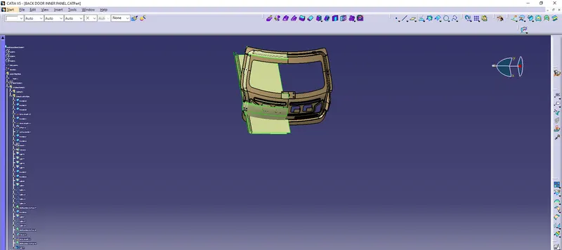
SEALING FLANGES LEFT:
- Insert a geometrical set Sealing Flanges Left.
- Sweep with reference surface, guide curve as curve smooth.13 & referance surface join.47 for 80mm & 2mm & 80deg
- Curve smooth the sweep.
- Insert a geometrical set sweep improvement under Sealing Flanges Left.
- Insert 4 parallel curves for the sweep performed.
- Split the sweep with 4 parallel curves.
- Insert 8 splines & 4 master sections surfaces.
- Join all splitted surface with master section surfaces.
- Sweep improvement is finished.
- Expolate offset.1 for 5mm
- Trim extrapolate.36 with join.49
- Trim offset.2 with join.49
- Extrude trim.15\edge.70, direction Line.15 Limit 1 as 66mm & Limit 2 as 32mm.
- Extrude trim.36\edge.71, direction Line.16 Limit 1 as 66mm & Limit 2 as 32mm.
- Split trim.35 with extrude.11
- Split trim.36 with extrude.12
- Multiple Extract join.47\edge.385 to join.47\edge.394
- Curve smooth the multiple extracted surface.
- Insert 2 splines.
- Insert 2 parallel curves.
- Split, trim.41 with parallel curve.76
- Split, extract.41 with point.16
- Insert a multi section surface.
- Join trim.43 & multi section surface.51

SEALING FLANGES RIGHT:
- Insert a geometrical set Sealing Flanges Right under construction.
- Sweep with reference surface, guide curve as mulriple extract.43 & reference surface as join.53 for length 1 & length 2 as 50mm & 2mm respectively & 80deg
- Multiple Extract join.53\edge.437 to join.53\edge.441
- Multiple Extract offset.1\face.38 & offset.1\face.39
- Extrapolate multiple extract.44 for 55mm
- Trim extrapolate.43 & sweep.6
- Multiple Extract ,trim.44\edge.443
- Insert a parallel curve , curve as multiple extract.45 & support as trim.44 for 2.8mm
- Split ,trim.44 with parallel.77
- Trim join.53 & split.98
- Multiple Extract ,trim.45\edge.449 to trim.45\edge.457
- Curve Smooth multiple extracted surface.
- Sweep with reference surface guide curve as curve smooth.21 & reference surface as trim.45 for length1 & length2 as 20mm & 2mm respectively & 80deg
- Insert a parallel curve , sweep.7\edge.458 & support as sweep.7 for 53mm
- Split sweep.7 with parallel curve parallel.78
- Trim, join.55 & extrapolate.48
- Insert a parallel curve, split.99\edge.87 & support as split.99
- Split, split.99 with parallel curve .80
- Split, split.99 with parallel curve .79
- Insert 2 splines.
- Insert a multi section surface.
- Join, multi section surface.54 , split.114 & split.115
- Extrapolate trim.45 for 2mm
- Insert a spline.
- Insert a multi section surface.
- Join, multi section surface.55 & trim .46
- Multiple Extract join.56\edge.500 & join.56\edge.509
- Insert a point.
- Split ,multiple extract.59 with point.27
- Blend ,first curve as curve smooth.23, first support as join.56 & second curve as split.116
- Extrapolate the blend for 42mm.
- Insert a spline & 2 points
- Split, extrapolate.49with spline.59
- Extrapolate, join.56 for 11mm
- Curve smooth multiple extract.58
- Trim, split.117 & extrapolate .50
- Trim, split.117 & trim.56
- Insert edge fillet , trim.57 for 3mm

MASTIC:
- Insert a geometrical set Mastic under construction.
- Draw a sketch.
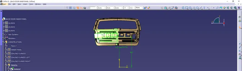
- Draw another sketch.
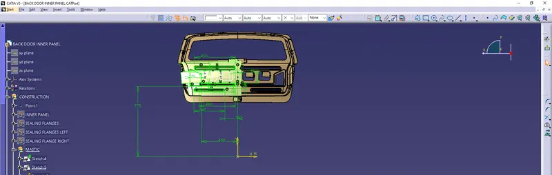
- Extrude the sketch4
- Split, edge fillet.12 with extruded surface
- Insert 2 points.
- Split, Extract.57 with 2 points point.30, point.31
- Again Insert 2 points.
- Split, Extract.58 with those 2 points Point.32, point.33
- Extract, offset.1\face.51
- Surfece Untrim the extracted surface.
- Sweep with reference surface , guide curve as split.119, reference surface as split.118 for 98mm & 80deg
- Sweep with reference surface , guide curve as split.120, reference surface as split.118 for 98mm & 80deg
- Offset the surface untrimmed surface for 4.8mm
- Trim offset.14 & sweep.11
- Insert a parallel curve trim.58\edge.521 for190mm
- Split offset.14 with parallel curve.81
- Trim , split.121 & sweep.10
- Then Insert 6 parallel curves.
- Split ,trim.59 with parallel curves 82,86 & 87
- Split ,trim.59 with parallel curves 83,84 & 88
- Insert a Bi-tangent fillet for support 1 as split.118 & support 2 as split.122 for 5mm
- Insert a Bi-tangent fillet for support 1 as split.123 & support 2 as fillet.1 for 3mm
- Insert 4 points & 4 splines.
- Split, fillet.2 with spline.62
- Split, split.124 with spline.61
- Split, split.125 with spline.60
- Split, split.126 with spline.63
- Edge Fillet for split.127 for 5mm
- Extrude sketch5.
- Split edge fillet.13 with extrude.22
- Sweep with reference surface , guide curve as curve smooth.24, reference surface as split.128 for 30mm & 80deg
- Sweep with reference surface , guide curve as curve smooth.25, reference surface as split.128 for 30mm & 80deg
- Sweep with reference surface , guide curve as curve smooth.26, reference surface as split.128 for 30mm & 80deg
- Offset Blend.3 for 5mm
- Extrapolate offset.15 for 42mm
- Trim , extrapolate.52 & sweep.14
- Trim , extrapolate.52 & sweep.12
- Trim , extrapolate.52 & sweep.13
- Join these 3 trims with split.128
- Insert a edge fillet to the joined surface for 5mm
- Then we have to make a cut out.
- Insert a geometrical set under the Mastic.
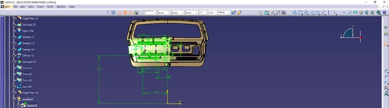
- Extrude the sketch.
- Split, edge fillet.18 with extruded surface
- Cut out is finished.
- Insert 5 points & 5 beads.
- Edge Fillet bead.6 for 2mm
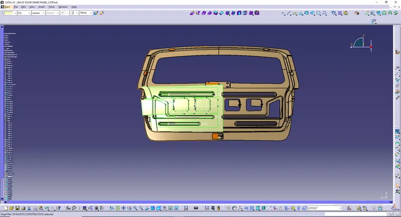
HINGE EMBOSS:
- Inser a geometrical set Hinge Emboss under construction.
- Insert a point
- Draw a sketch.
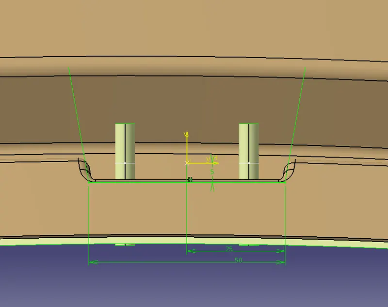
- Extrude this sketch.
- Sweep with reference surface , guide curve as extrude.24\edge.546, reference surface extrude.24 for 30mm & 80deg
- Sweep with reference surface , guide curve as extrude.24\edge.547, reference surface extrude.24 for 30mm & 80deg
- Join sweep.17, sweep.18 & extrude.24
- Trim edge fillet.19 & join.59
- Insert edge fillet for trim.64 for 2mm
- Draw a sketch.
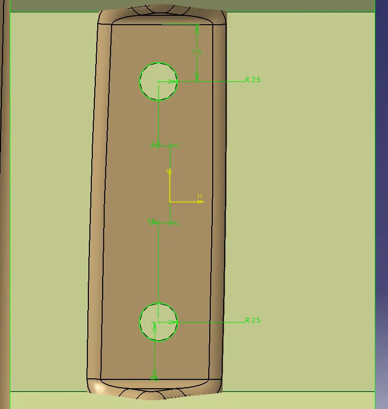
- Extrude the sketch.
- Split edgefillet. 20 with extrude.25
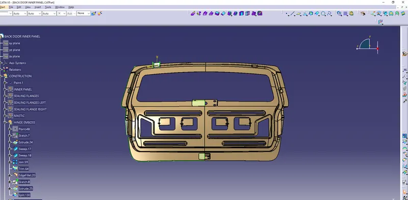
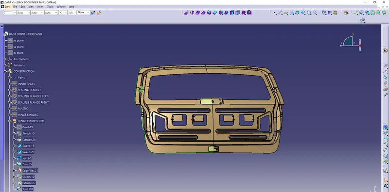
HINGE EMBOSS SIDE:
- Insert a geometrical set Hinge Emboss Side inside the construction.
- Insert a point.
- Draw a sketch.
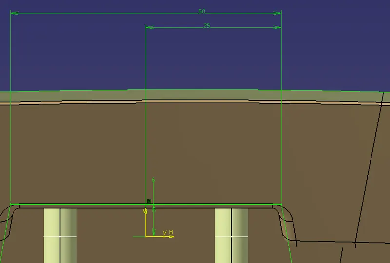
- Extrude the sketch.
- Sweep with reference surface, guide curve as extrude.26\edge.548, reference surface extrude.26 for 30mm & 80deg
- Sweep with reference surface ,guide curve as extrude.26\edge.549, reference surface extrude.26 for 30mm & 80deg
- Join both the sweeps with extruded surface.
- Trim , split.130 & join.60
- Insert a edge fillet for trim.65 for 2mm
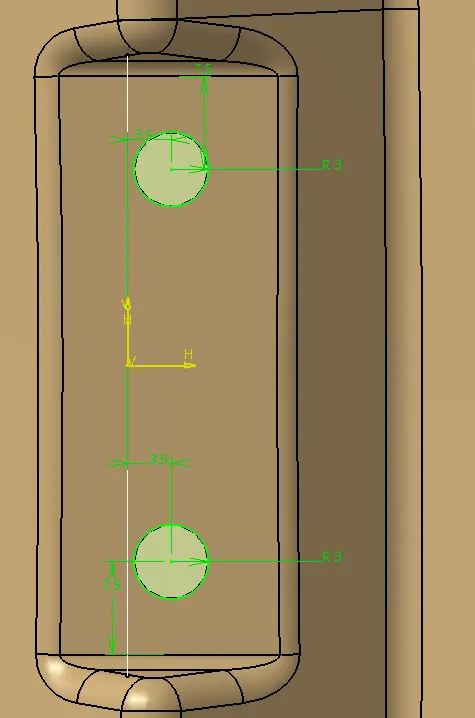
- Extrude the sketch.
- Split, edge fillet.21 with extrude.27
WIPER MOUNTING EMBOSS:
- Insert a geometrical set Wiperr Mounting Emboss under construction.
- Draw a sketch.
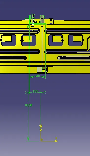
- Extrude the sketch
- Split, split.131 with Extruded surface.
- Sweep with reference surface, guide curve as extract.66, reference surface split.132 for 30mm & 80deg
- Insert a parallel curve , curve assweep.22\edge.132 & support as sweep.22 for 8mm
- Split, sweep.22 with parallel curve.93
- Split, sweep.22 with parallel curve.94
- Insert 2 splines.
- Insert Multi Section surface.
- Join, multi section surface.56, split.133 & split.134
- Draw a sketch.
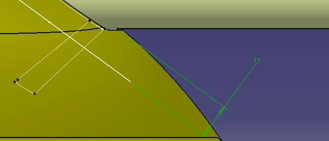
- Extrude the sketch.
- Trim extrude.29 & join.61
- Draw a sketch.
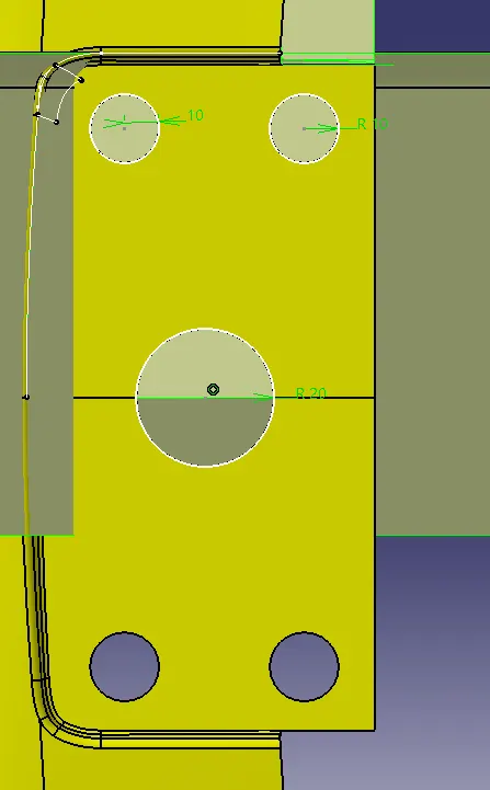
- Extrude the sketch.
- Split, trim.66 with extruded surface.
- Insert a Bi-tangent Fillet , support 1 as split.132 & support 2 as split.135 for 2mm
- Insert a edge fillet for support as fillet.3 & for object to fillet as fillrt.3\edge.133 for 2mm
- Draw a sketch.
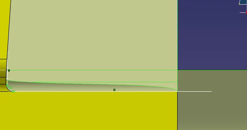
- Extrude the sketch.
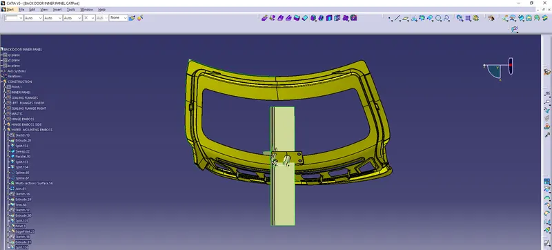
- Split edgefillet.23 with extruded surface.
LATCH EMBOSS:
- Draw a sketch.
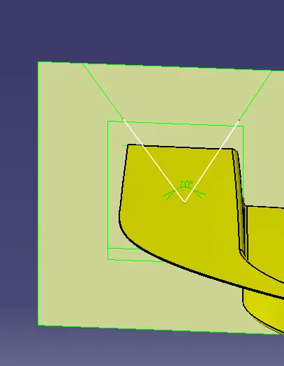
- Extrude the sketch.
- Draw a sketch.
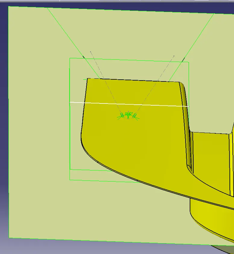
- Sweep it with draft direction, guide curve as sketch.20 & draft direction as x component For lenth 1 & length 2 for 31mm & 47mm respectively for 10deg
- Offset sweep.25 for 40mm
- Extrapolate offset.18 for 42mm
- Trin extrude.32 & extrapolate.53
- Trim split.136 & trim.67
- Apply edge fillet for trim.68 for 2mm
- Draw a sketch.
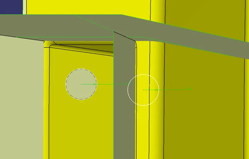
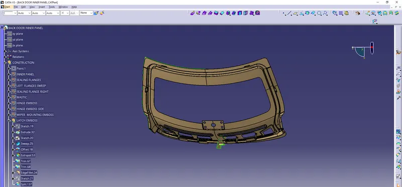
- Split edge fillet.24with sketch.21
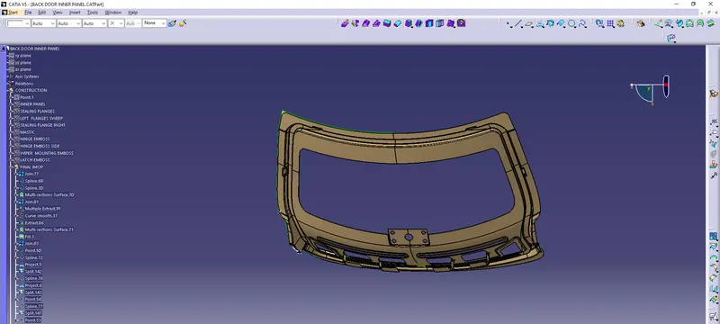
FIAL IMOP:
- Insert ageometrical set Final Imop under construction.
- Join split.137
- Insert 2 splines.
- Insert Multi Section surface.
- Join multi section surface & join.77
- Multiple Extract join.81\edge.618 & join.81\egge.619
- Curve smooth multiple extract.
- Extract join.81\edge.622
- Insert a Multi Section surface.
- Fill join.81\edge.623 , curve smooth.37 , extract.86 & spline.70
- Join fill & join.81
- Insert a point.
- Insert a spline.
- Project spline.72 & support as split.140
- Split, split.140 with project.5
- Insert a spline.
- Project spline.76 & support as split.142
- Split, split.142 with project.6
- Insert a point.
- Insert a spline.
- Split, split.143 with spline.77
- Insert a point.
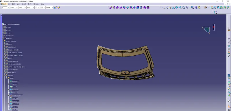
HEMMING:
- Insert a geometrical set Hemming under construction.
- Insert a geometrical set Final under Hemming.
- Intially insert a boundary for, surface edge join.83\edge.624, Limit 1 as join.83\vertex.169 & Limit 2 as join.83\vertex.170 with point continuity
- Insert a corner Element 1: Extract.88 & Elemrnt 2: Extract.89 & support as join.83 for 30mm
- Trim corner.2 & boundary.1
- Insert a parallel curve.
- Project parallel.96 & support as join.83
- Curve Smooth project.2
- Split join.83 with curve smooth.38
- Insert a boundary for, surface edge split.139\edge.625, Limit 1 as split.139\vertex.171 & Limit 2 as split.139\vertex.172 with point continuity
- Insert a parallel curve.
- Project parallel curve.97 & support as split.139
- Split, split.139 with project.4
FINAL:
- Insert a geometrical set Final under construction.
- Extrapolate split.147 for 10mm
- Split ,extrapolate.56 with xy plane.
- Symmetry , split.148 with xy plane
- Finally Join , split.148 & symmetry.3
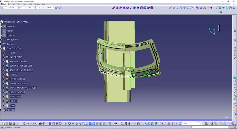
SOLID MODEL OF BACK DOOR iNNER PANEL:
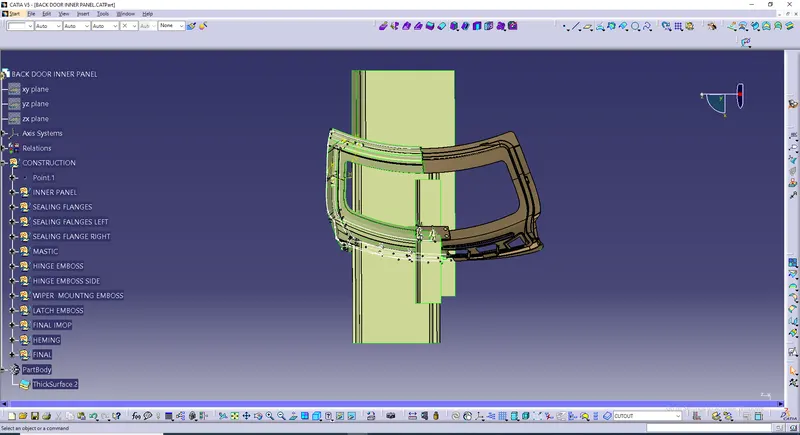
FINAL ASSEMBLY PART: