Design of backdoor
Aim-
To design the outer upper & lower panel, inner panel with the necessary reinforcements by following the Master section with the design parameter for the given class a surface.
Introduction- A door is a hinged part which is used for entry & exit of the vehicles. Back doors are one of the type doors of the vehicle which are located next to the passenger seat which provide access to the luggage compartment. In most of the cars, these back doors are operated with the help of gas stay which in turn reduces the effort required to lift open the door. Some luxury cars have powered backdoor which in turn is driven by an electric motor. This kind of system is also called a powered trunk lid system.
Components to create-
��������� Upper panel
��������� Inner panel
��������� Gas stays reinforcement LH & RH
��������� Hinge reinforcement LH & RH
��������� Striker reinforcement
��������� Wiper reinforcement�
Procedure-
1. Geometry- We get a class A surface of the back door.
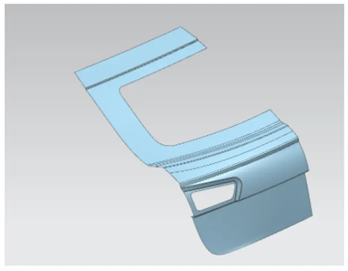
2. Tooling axis creation- Draw a line from left & right extremities almost parallel to the path of the surface along the unsymmetrical axis. Using derived lines tool, create a bisecting line as shown below..
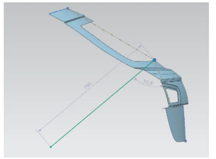
3. Creating Inner panel- First offset the surface to a distance of 1.7 mm, which will give the innerpanel surface position. Now the sealing flange for the inner panel has to created. The sealing flange created by cutting from the surface is shown below-
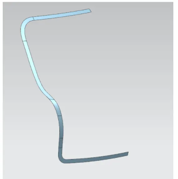
In between, the tangent tensioning can be adjusted by modifying the surafce using the bridge curve tool. This flange has to be in a depth of 30 mm from the surface. Now connect the flange with the surface using law extension w.r.t the tooling axis & proper draft given.
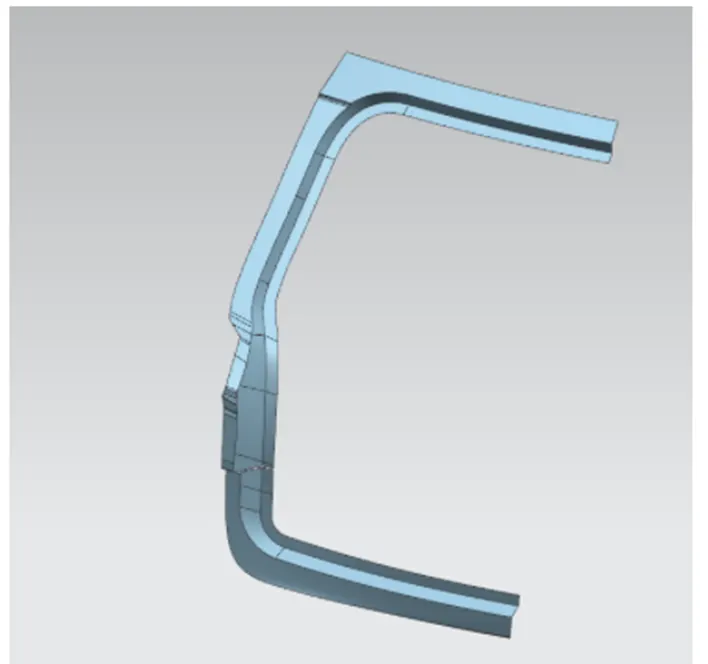
Fillets has to be applied at each steps & check whether the surface is getting thickened or not. The next step is to create the other side which has to be connected with the sealing flange.
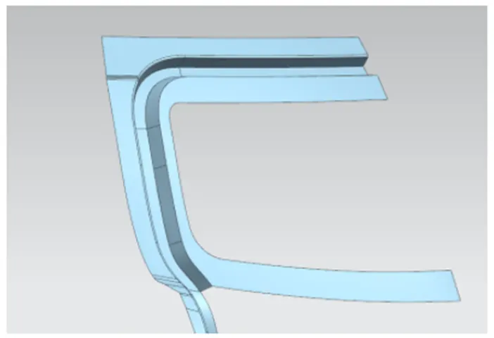
Similarly connect the lower side of the surface by creating a surface & sew it all together.
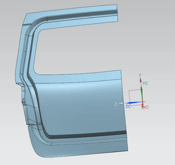 .
.
Mastic sealant is used on the surface to connect the inner & outer panel with a gap of 5mm.
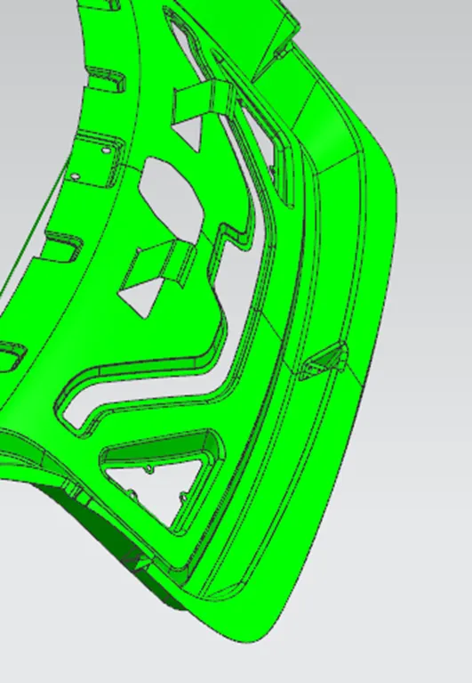
So offset the outer surface 5mm downwards & create a plate from the inner panel. Give proper embosses & cut-outs in the surface of the inner panel which is shown below-
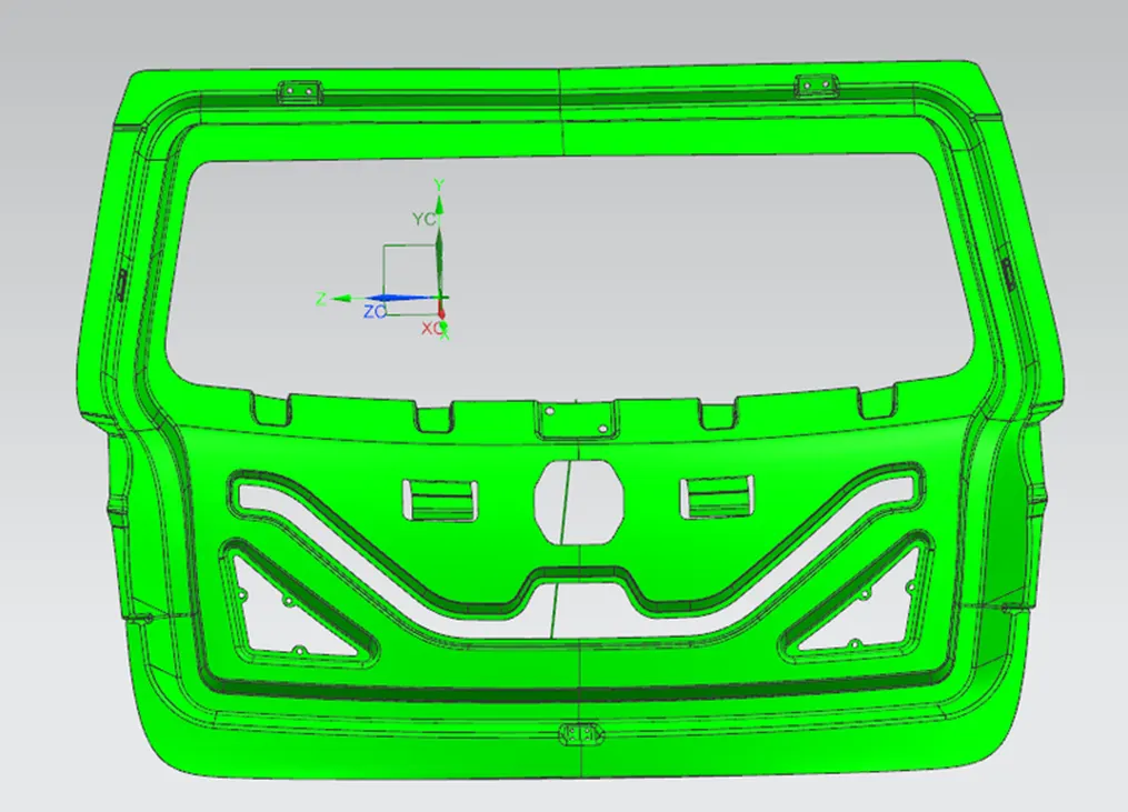
Now, embosses has to be created for the hinge, Gas stay, Latch & striker as well as the wiper motor areas.
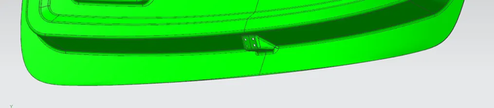
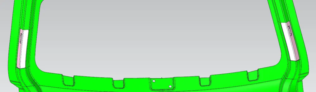
4. Creating Reinforcements- The reinforcements can be directly offseted from inner panel surface using the wave geometry linker & trim it accordingly. To create striker emboss the circle was drawn and line perpandicular to tangent of that circle was drawn. As sown in below image. All reinforcements are shown below
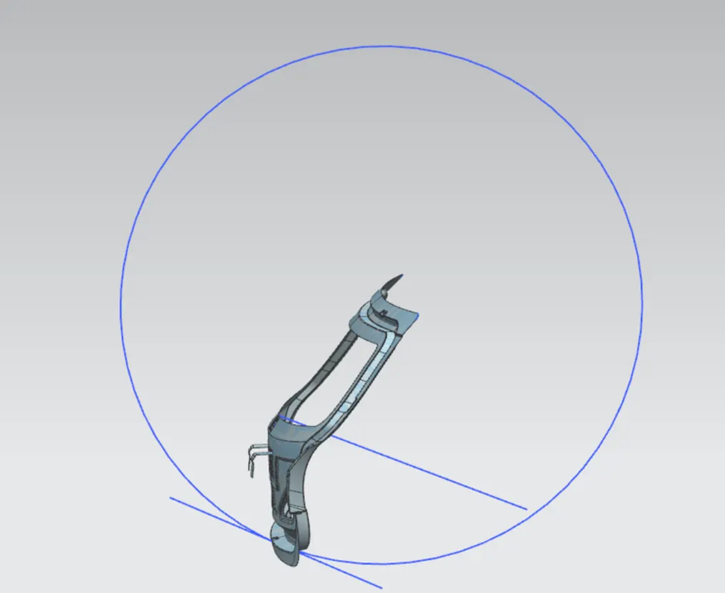
Hinge Reinforcement LH and RH:

Gas Stay Reinforcement LH and RH:
5. Outer Panel Creation-upper- Offset the surface to a distance of 2.65mm, so that 0.2 mm of clearance can be given in between the surafces.
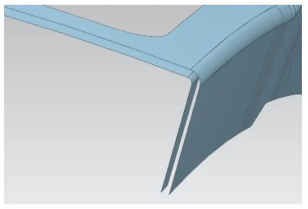
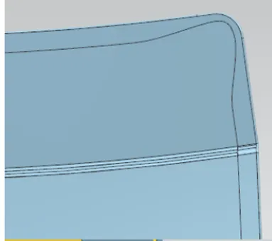
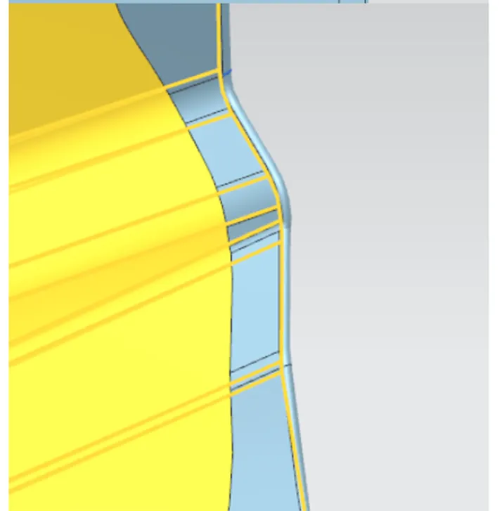
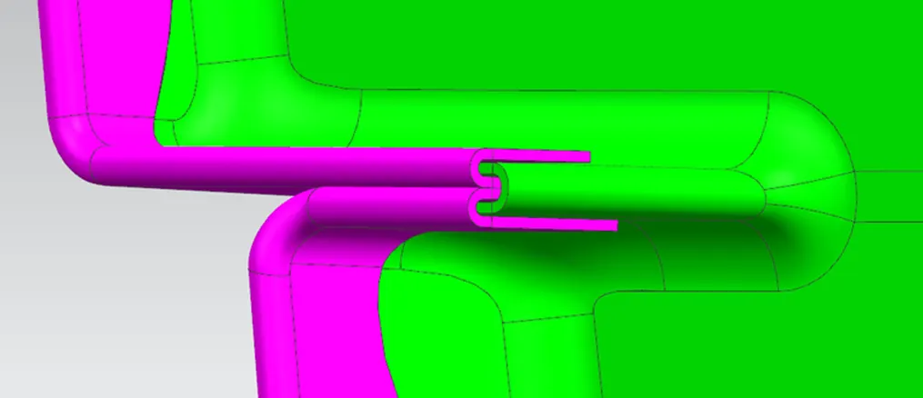
Create the hem using the through curve mesh or swept tools in the surface panel. Reliefs has to be given in the corner areas for the easy manufacturability.
 � �
� �
�
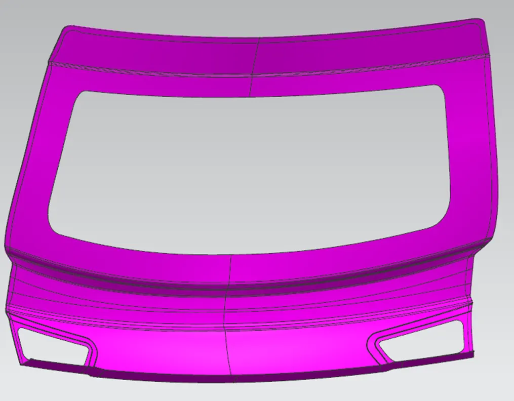
The final part after creating the hem is shown below-
6. Outer panel creation-Lower-
The same steps has to be followed for lower surface as well.
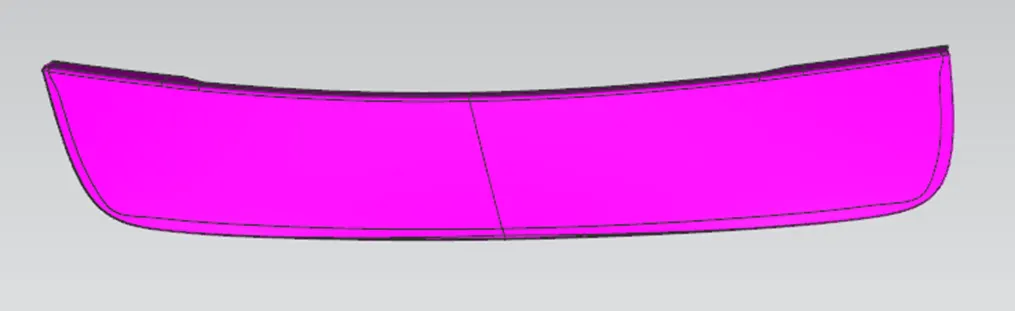
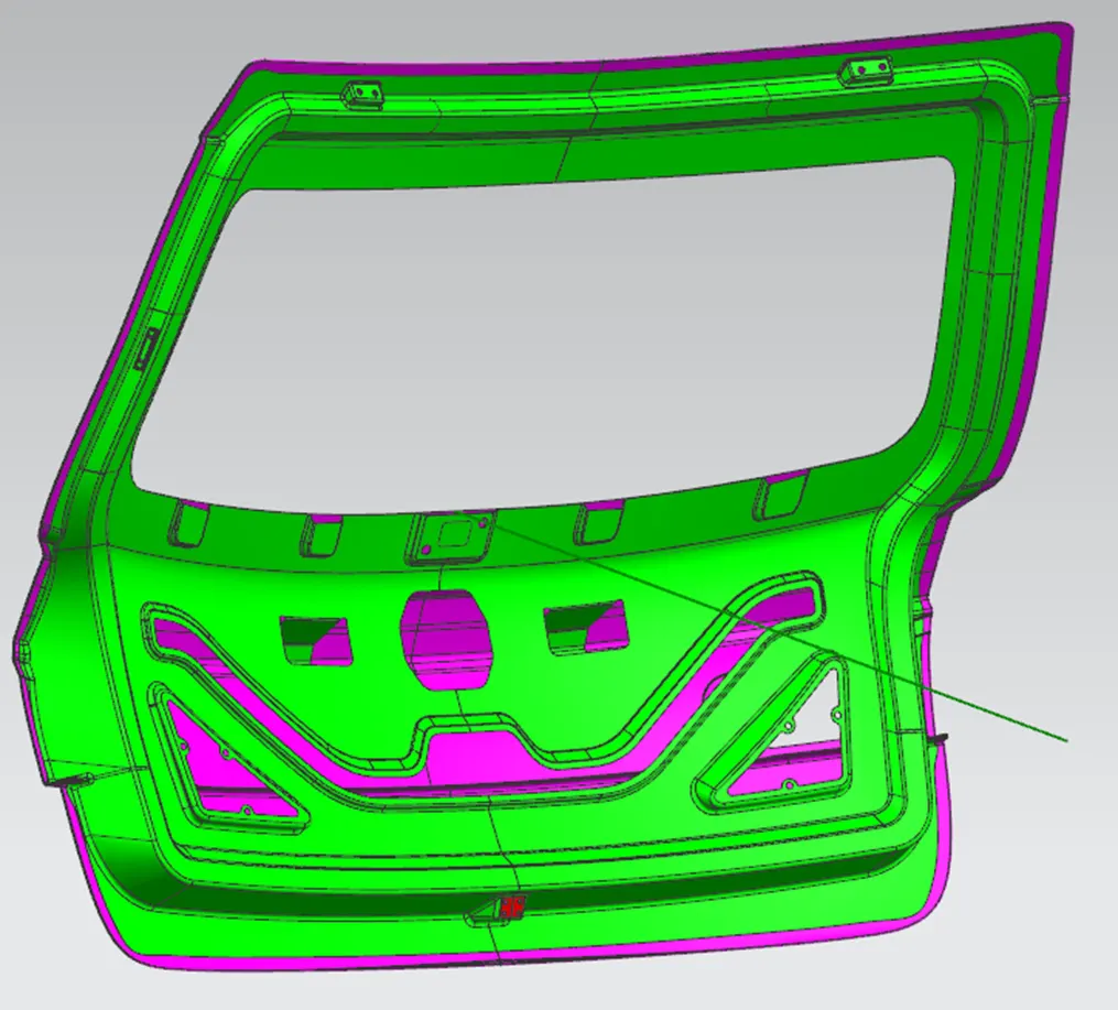
The thickened part after the assembling of all these components is shown below-
DRAFT ANALYSIS:
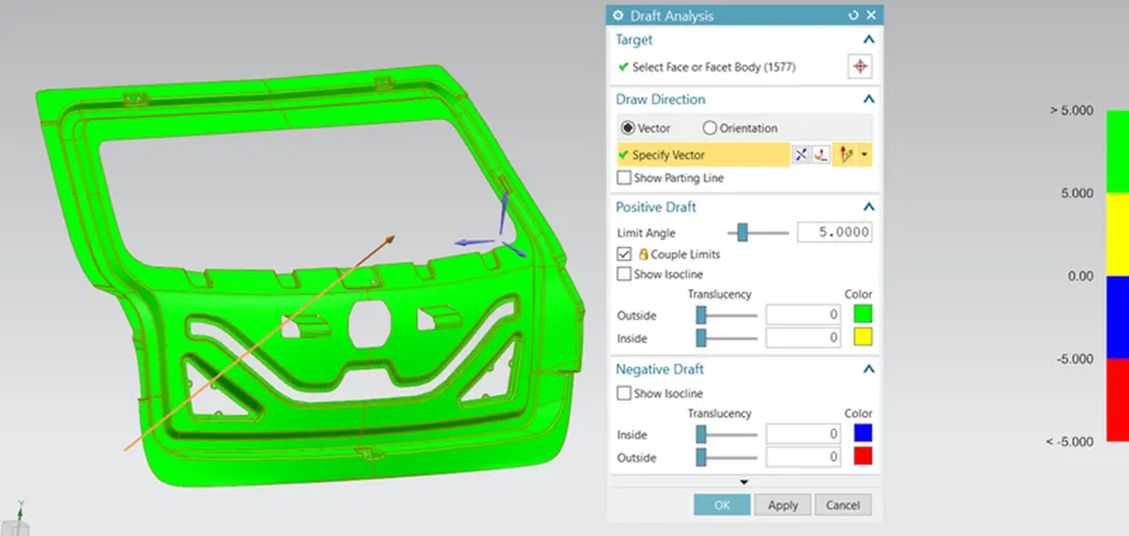
Draft analysis of inner panel is carried out through the tooling direction only.Only the green areas are acceptable and i worst cases yellow regions are accepted but the blue and red regions are never accepted.
The draft angle for aluminium casted panel is 2 to 3 degrees is enough but if it is steel then the angle is more than 7 degrees.
In this project i considered it as steel and used 7 degrees as draft angle and direction is choosen as tooling direction which is the deep drawn direction.
Conclusion:
The back door assembly is modeled following the engineering standards from the given styling surface.
1. Sealing Flange of length 25mm is maintained throughout.
2. Thickness for the reinforcement is 1.5mm.
3. Emboss are drawn with respect to the tooling axis so that they clear the minimum draft angle.
4. Corner relief is given to prevent unwanted deformation of the sheet metal at the corners while hemming