Design of backdoor
AIM
The aim of this project is to design the Body in white parts of the back door of a SUV vehicle, along with designing the reinforcements for hinges, gas stay, latch and wiper motor for the back door.
INTRODUCTION
The back door of the car is one of the closure commodity of a vehicle which is present at the back portion of the car. While designing the back door space requirements are also taken into consideration as luggage room is also present in this region.
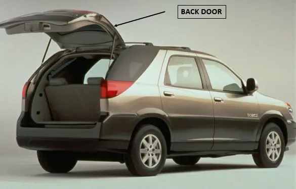
There are two types of back doors:
1. Tail Gate
These are hinged on the top and rotate about a horizontal point. Tailgates are more widely used on car derived vans, kombis and minibuses, but can often be chosen as a no-cost option on the larger panel vans.
Pro’s for Tailgate:
· The tailgate gives a better view out the back unlike Barn Doors, as there’s no central pillar in the rear window, which means wipers are often also included.
· They can give shelter from the rain when stood under it (providing it's not too windy).
· The twin door is quicker to get something out the back in really bad weather without soaking or blowing everything and everyone around inside.
· They’re also less likely to get bumped, as it lifts up and out of the way of people and materials, whereas Barn Doors often get caught in the way which results in scratches and dints. However, the flip side to this is when the van is parked facing uphill, or on a slant, the tailgate could be held at a ‘head hazard’ height.
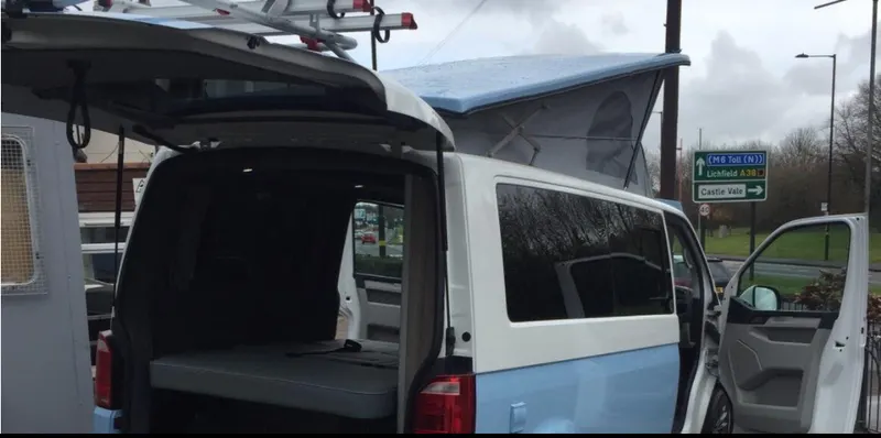
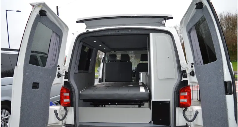
2. Barn Doors
These are hinged on the side of the van and rotate about a vertical point. Barn Doors are a standard feature for medium and large panel vans.
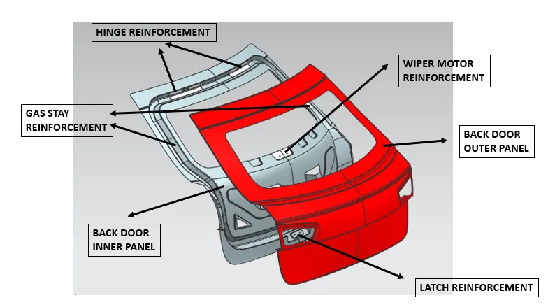
The components designed in this project are:
1. Back Door Outer Panel
2. Back Door Inner Panel
3. Hinge Reinforcement LH and RH
4. Gas Stay Reinforcement LH and RH
5. Wiper Motor Reinforcement
6. Latch Reinforcement.
The above components are shown in the below image
PROCEDURE
1. INPUT STYLING SURFACE
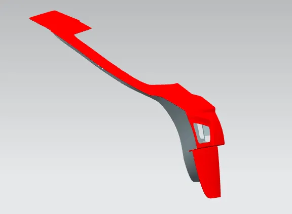
The styling surface is the surface which is provided as input in order to design the back door as per requirement of the customer.
The below image shows the input styling surface:
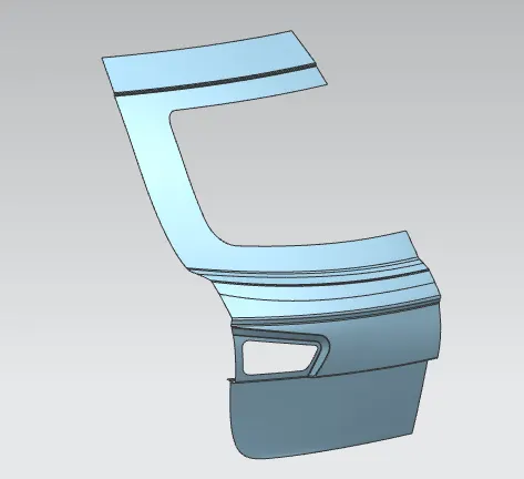
The above surface analysed and it was observed that the surface provided was having uneven surface quality.
The surface quality of the above class A surface was improved at the required positions using bridge curve and through curve mesh feature to improve the surface quality and then make the outer and inner panel of the back door panel.
2. Back Door Inner Panel
Determination of Tooling Axis:
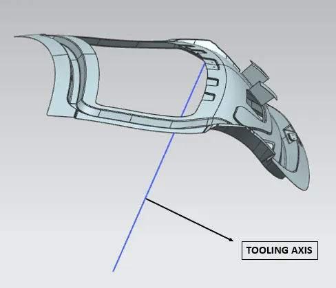
The tooling axis plays an important role while making a component. It is the axis of line along which the component will be extracted after the component is been moulded.
In this project the tooling axis is made by making two lines touch the opposite ends of the styling surface and then a bisecting line is drawn between these two lines to determine the tooling axis line.
The below image shows the tooling axis line:
Determination of emboss shape and direction:
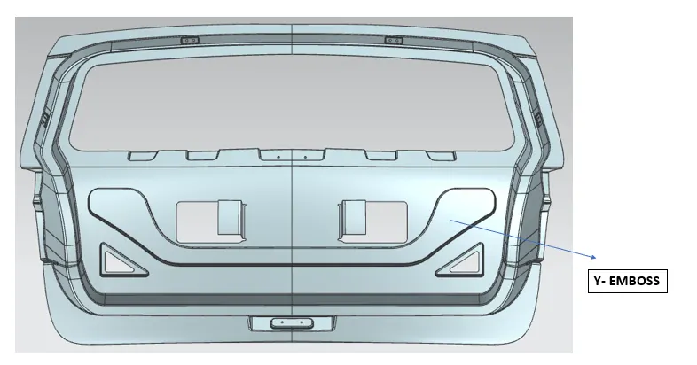
As the back door open and closes in the upward and downward direction, during this time force is generated on it which might effect the durability of the back door panel. This generated force is dissipated in the outwards direction with the help of creating an emboss in the Y shape.
The below image shows the Y emboss
In order to firmly fix the outer panel to the inner panel a mastic extension flange is protruded towards the outer panel direction so that mastic can be applied on it and then the outer panel and the inner panel will have more strength in the middle portion and stick with each other firmly.
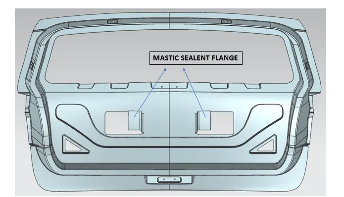
The above image shows the position of the flanges on the back door inner panel.
Embosses:
In order to provide strength to the inner panel various embosses are designed on it to fix the reinforcement on the inner panel firmly.
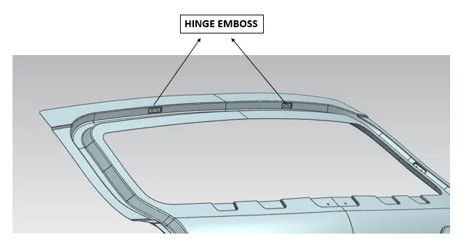
1. Hinge Emboss
Hinges will be placed on the top side of the inner panel in the left and right side. In order to fix the hinge to the inner panel embosses are designed on the back door inner panel.
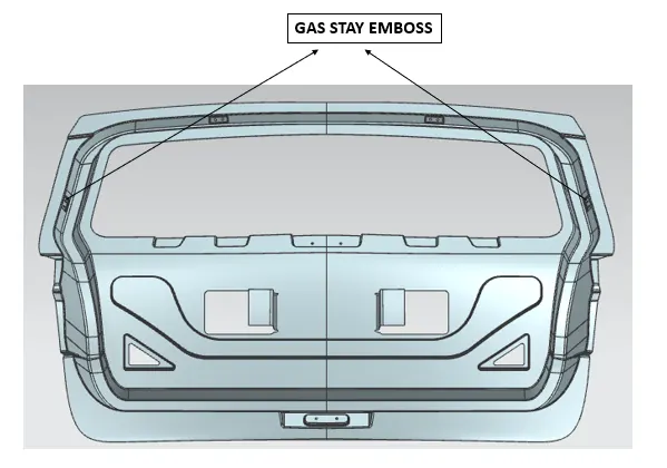
2. Gas Stay emboss
Gas stay is the component which is used to lift and lower the back door automatically with the help of pressing a button. This is placed on both the left and right side of the back door.
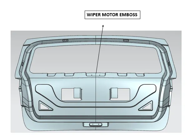
3. Wipe Motor Emboss
The wipe motor emboss is designed at the middle of the back door where the wiper motor will be placed on the back door. In order to clean the glass of the back door this mechanism is used on the back door.
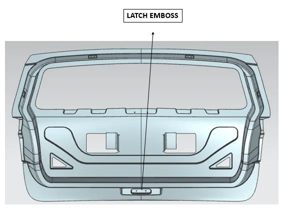
4. Latch Emboss
This emboss is designed at the bottom portion of the back door. This system is used for locking the back door to the car.
REINFORCEMENTS
Reinforcements are the components which are used to add strength at a particular region.
The reinforcements designed for the back door are:
1. Hinge Reinforcement LH and RH
2. Gas Stay Reinforcement LH and RH
3. Wiper Motor Reinforcement
4. Latch Reinforcement
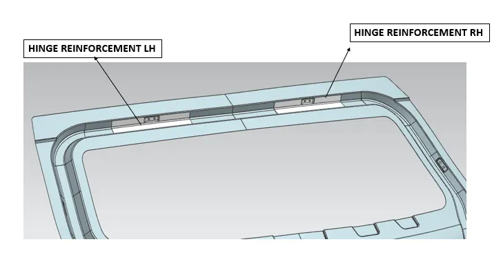
1. Hinge Reinforcement
The Hinge reinforcement will be placed on the embosses of the hinges which will enable it to fix the reinforcement firmly to the back door at required position.
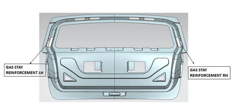
2. Gas Stay Reinforcement
Gas Stay reinforcement are designed to provide strength to the region where the back door will get opened and closed with the help of gas stay rods. For the purpose of durability these reinforcements are placed where the gas stay will be fixed with the back door panel.
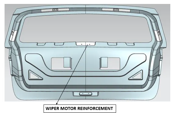
3. Wiper Motor Reinforcement
Wiper Motor Reinforcement is placed at the middle portion of the back door to provide strength in this region for the placement of wiper motor.
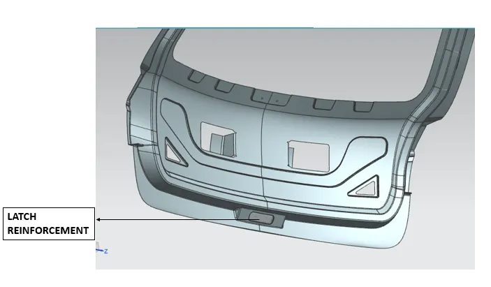
4. Latch Reinforcement
In order to place the latch at correct position a trajectory is made so that the back door is opened and closed following a trajectory without facing any obstacles. A circular sketch is drawn first to and which will show the trajectory of the path that the back door will follow while opening and closing, the latch position will be perpendicular to this circular trajectory at all the positions of the movement of the back door.
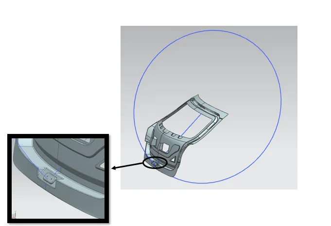
From the above image we can observe that the latch is designed perpendicular to the circular trajectory which will enable the back door to open and close freely.
In order to provide strength in this region a latch reinforcement is placed which is shown in the below image:
HEMMING REGION
The back door outer panel will be fixed with back door inner panel with the help of hemming which will be done on the outermost edges of the outer panel. In this process the surface is bend and rounded around the inside surface so that it firmly holds the inside panel. Along with this mastic solvent will also be inserted inside this region for firmly sticking the outer panel with the inner panel.
The below image shows the hemming region designed.
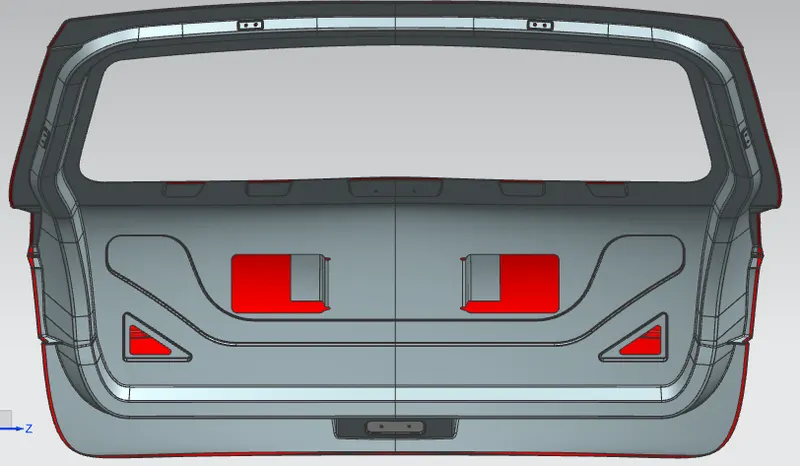
From the above image we can observe that the back door outer panel edges are rounded around the inner panel near the boundary region.
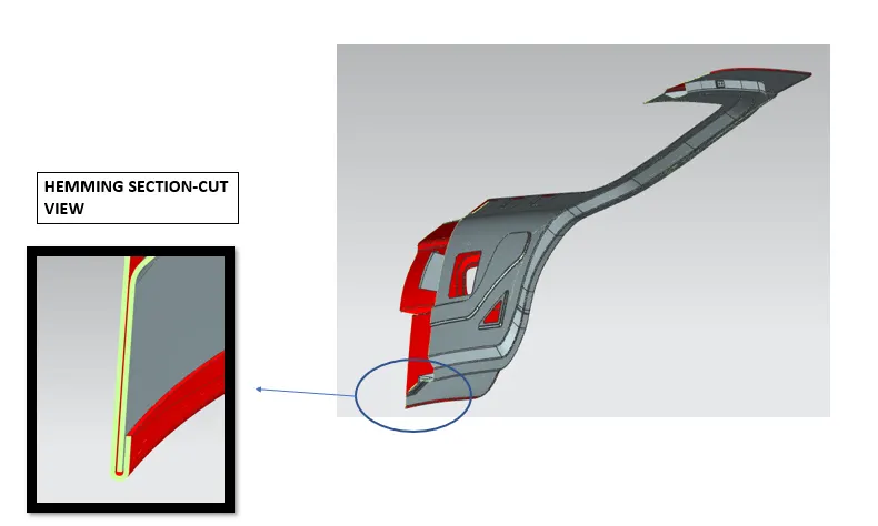
The above image shows how the hemming region looks around the boundaries.
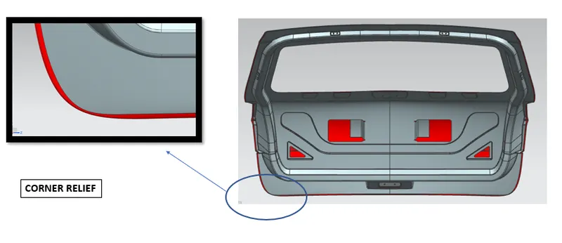
Corner Relief are also provided at the corners so that the hemming can be easily performed in all the regions.
DRAFT ANALYSIS
After completing the complete assembly of the back door inner panel, draft analysis is performed on it to check whether the component can be easily tooled along the tooling direction and it does not have any undercuts.
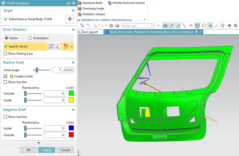
From the above image we can observe that the inner panel cab easily be manufactured along the tooling direction as it is clearing in all the regions. We can also observe that only the mastic flange is not clearing so it need to be manufactured separately in order to make the mastic sealant flange for the inner panel of the back door.
DIFFERENT VIEWS OF THE BACK DOOR ASSEMBLY
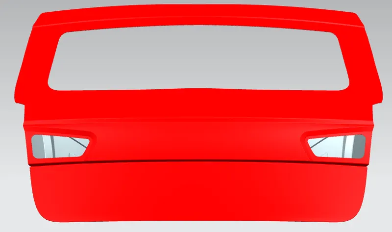
1. FRONT VIEW
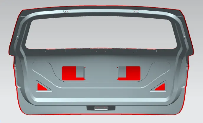
2. BACK VIEW
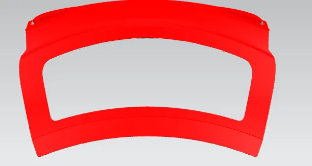
3. TOP VIEW
4. SIDE VIEW
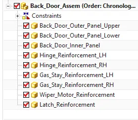
ASSEMBLY TREE STRUCTURE
CONCLUSION
1. The back door outer and inner panel were designed with the help of the styling surface along the tooling direction.
2. Draft analysis was performed on the inner panel and it was concluded that the component can be easily manufactured along the tooling direction.
3. All the reinforcements were designed and placed at appropriate positions to provide strength at critical regions.