Design of backdoor
Design of Backdoor
Objective: To design Back door of car using the given Class ‘A’ surface.
Functions of the Backdoor:
- It protects the occupants and luggage from getting damaged.
- It houses assembly of tail lamps, wiper motor and other components.
- It serves as entry and exit point for luggage/passengers.
- It houses windshield glass which helps in rear visibility.
- Parking sensors, rear view camera are mounted on it
DESIGN CONSIDERATIONS:
- It should satisfy the real visibility criteria.
- It should provide adequate boot space for easy loading and unloading of luggages.
- It should have embosses and reinforcements wherever necessary.
- The latch and striker should follow the trajectory at the middle of the hinge mounting axis to ensure the safety of openning and closing of backdoor at proper angles.
- It should provide an air-tight sealant when the door is closed.
- It should have proper space for wiper motor,tail lamp and all other mountings etc.
Different Sheetmetal processes used for manufacturing the Back Door
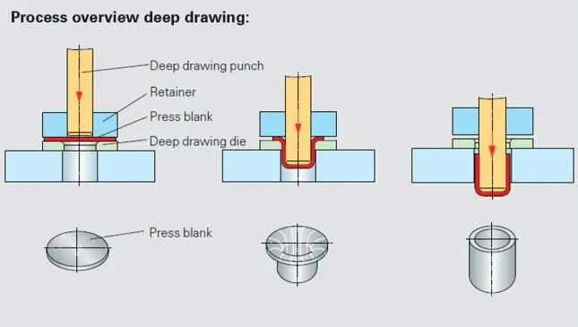
Deep Drawing:
The metal deep drawing process is an effective method of manufacturing of cups, cans and other similar deep drawing products. The deep drawings having two main categories.
- First- stage drawing: The blank shape of metal is placed on the die and contact with the punch. When the metal specimen is flat piece of sheet metal used in forming and finish the product. Initially the punch moves in downward direction. The outer rim of blank is subjected to pure radial drawing (drawing toward in vertical axes) between die and blank metal. The metal become a bend and sliding over die and also stretched between die and punch. The metal in vicinity of punch head and contact with it bend and slide over radii and stretch over punch head.
Redrawing: The components drawn from first stage again it is redrawn convert into more depth to form a cup shape in the die and punch. The second stage of drawing is called as redrawing.
Embossing:
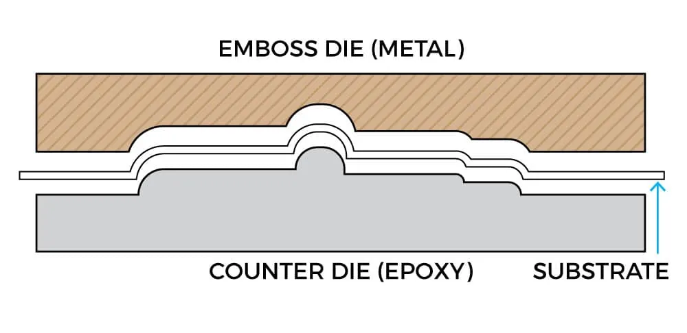
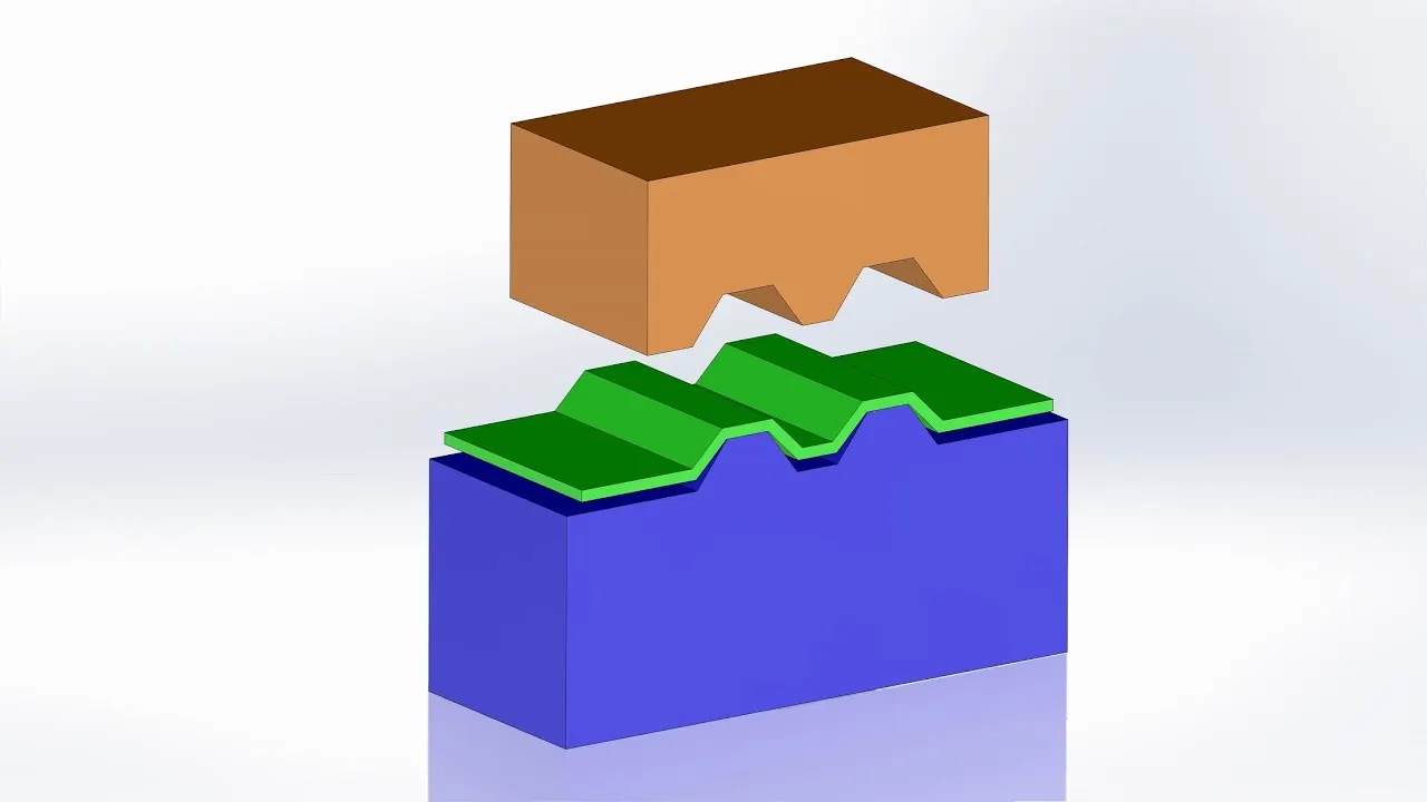
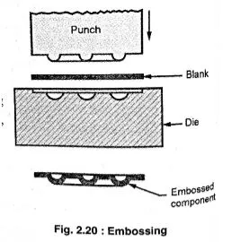
Embossing is a metal forming process for producing raised or sunken designs or relief in sheet materials by means of matched male and female roller dies, theoretically with no change in metal thickness or by-passing sheet or a strip of metal between rolls of the desired pattern. Metal sheet is drawn through the male and female roller dies producing a pattern or design on the metal sheet. Depending on the roller dies used, different patterns can be produced on the metal sheet.
Materials commonly used in the metal embossing process include:
- Aluminum alloys
- Steel alloys
- Zinc
- Copper
- Galvanized steel
- Brass
- Cold rolled steel
Metal Stamping Technologies
Metal Stamping:
The metal stamping process began during the industrial revolution as a cold forming means for producing frames and handlebars for bicycles. From its beginnings in Germany, it has grown into an essential part of modern industry for the production of parts and components for a wide variety of industries. The early auto industry transferred its parts production from forging to metal stamping because of the lower cost of the stamping process.
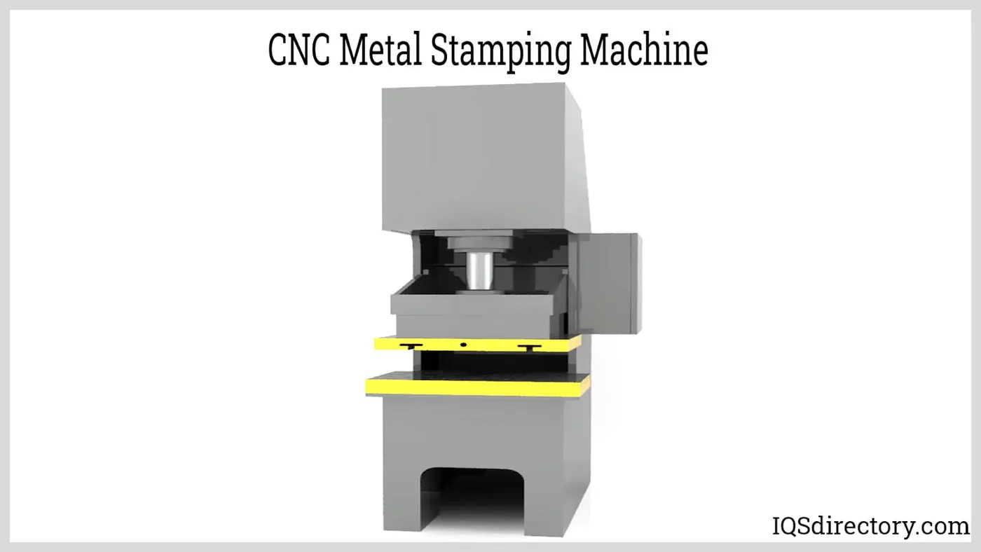
Metal stamping is a relatively simple process where rolled or sheet metal referred to as a blank, is placed in a press that has a die in the desired shape of the part. With force and compression, the die is pressed into the metal. After a predetermined amount of time, a partially completed part is removed. Though this may seem very easy to understand, in reality, there are several different steps that need to be taken that include trimming, finishing, and other procedures designed to produce the finished part.
Hemming:
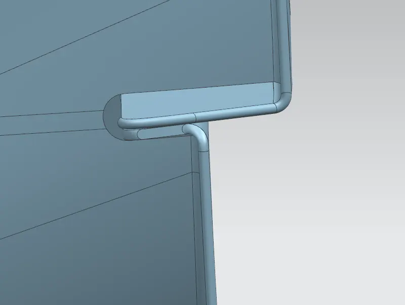
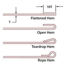
Hemming is a forming operation in which the edges of the sheet are folded or folded over another part in order to achieve a tight fit. Normally hemming operations are used to connect parts together, to improve the appearance of a part and to reinforce part edges.
In car part production, hemming is used in assembly as a secondary operation after deep drawing, trimming and flanging operations to join two sheet metal parts (outer and inner) together. Typical parts for this type of assembly are hoods, doors, trunk lids and fenders.
There are various types of hemming operations:
- Conventional die hemming: In conventional die hemming, the flange is folded over the entire length with a hemming tool.
- Roll hemming: In roll hemming, the hemming roller is guided by an industrial robot to form the flange.
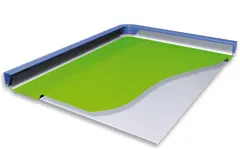
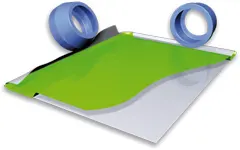
Open Hem: A Hem has a full round feature and a return flange. In open hem bend angle is equal to 180 degrees.
Tear drop Hem: In tear drop hem the bend angle is greater than 180 degrees.
Closed Hem: Hems without any inside radius are called as closed hem. Closed hems are not recommended if the hem geometry is to be painted or if the material used is SST or Aluminium.
Corner Relief
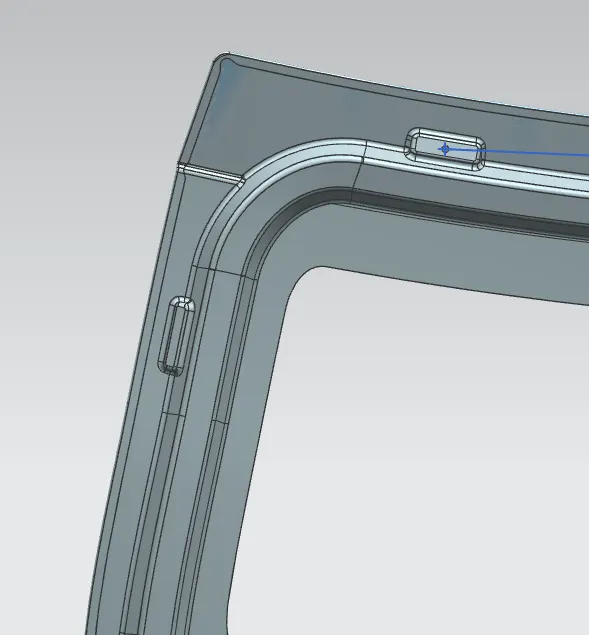
Corner relief has to be provided for sheet metal bending. In this case, before the hemming process to control the deformation of the sheet metal and to avoid any tear of the sheet metal during bending.
Blanking:
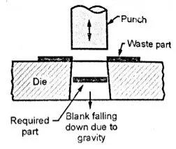
Blanking is a cutting operation of a flat metal sheet and the article punched out is known as blank. Blank is the required product of the operation and the metal left behind is considered as a waste.
Punching:
It is similar to blanking only the main difference is that, the hole is the required product and the material punched out from the hole is considered as a waste.
Spot welding:
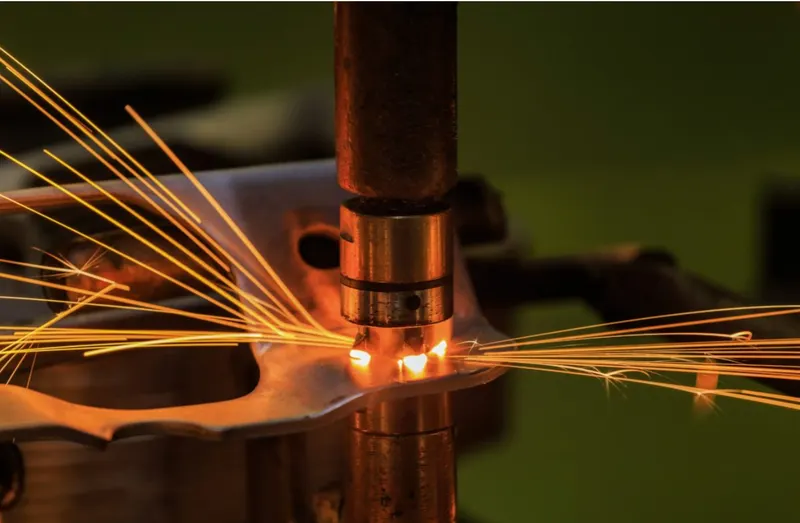
Spot Welding is a form of resistance welding also known as Resistance Spot Welding (RSW). Spot Welding involves using heat produced by resistance to an electrical current to join materials together. The current heats the materials to a point where they become malleable. The use of strong pressure bonds them together.
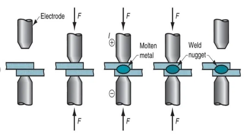
Another form of resistance welding is Projection Welding. This process involves fusing a fastener’s embossed or coined projections to the metal base material to form a weld. As the materials never melt, they do not intermix. This means the resulting weld is more like a forging of the materials.
Spot welding is only suitable for a small selection of base materials. Low carbon steel is the most suitable material for spot welding. This is because it is more resistant to electricity and has a lower thermal conductivity than the copper electrodes used to create the required electrical current.
High carbon steels and aluminium alloys can form brittle welds that don’t last with the spot welding process. Pure aluminium can qualify for spot welding but requires higher current levels. This is because it has a lower resistance to electricity than low carbon steel.
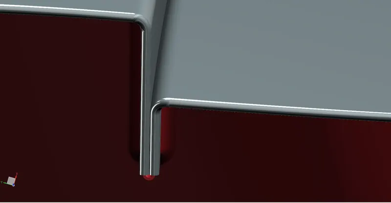
The outter panel upper and outter panel lower are joined through the spot welding .So there must be no gap between the outter panel upper and outter panel lower.
Design of Back door in NX CAD:
Door parts thickness is given below,
- Outer Panel - 0.75 mm
- Inner Panel - 0.75 mm
- Reinforcements - 1.5 mm
Parts Of the BackDoor
Inner Panel
Hinge Mounting Bracket ( LH & RH )
Gas Stay Bracket ( LH & RH )
Wiper Motor Support Bracket
Latch
Latch Reinforcement
Hinge reinforcement ( LH & RH )
Gas Stay Reinforcement ( LH & RH )
Given Data,
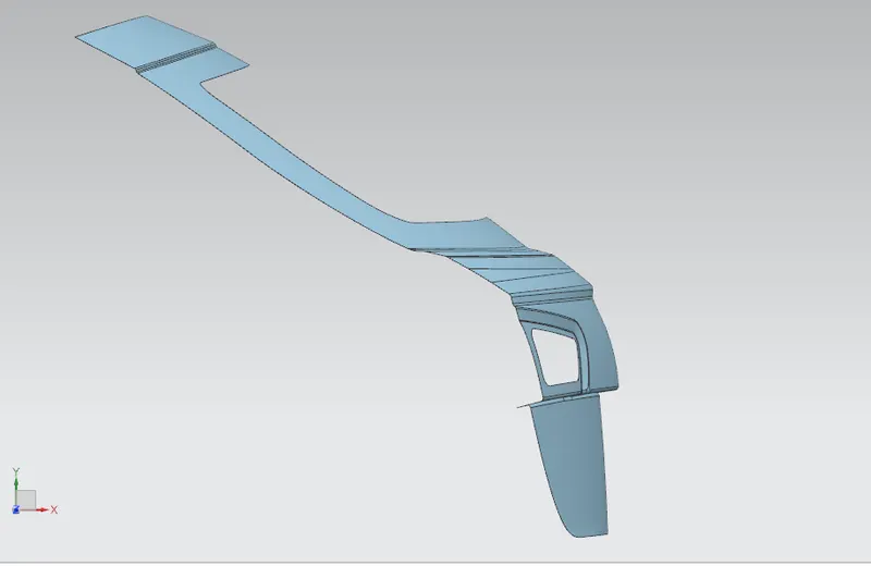
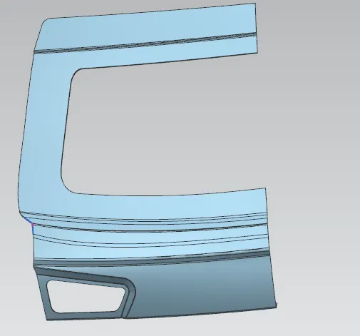
Given class-A surfaces has to be repaired according to the smoothness. After repairing the surfaces, the door is divided into two parts as Door Outer Upper and Door Lower Panel.
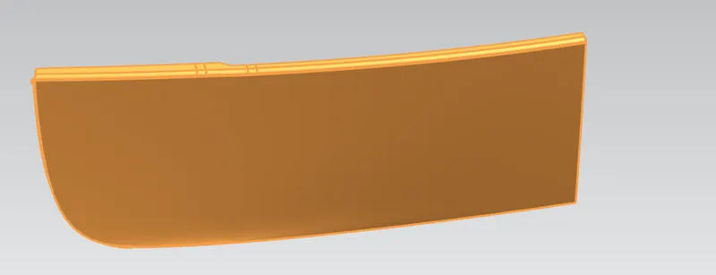
First, we need to create the Tooling direction for the Deep drawing operation. It shows that all the operations like embossing is done by considering this vector direction and it will help in manufacturing the part,
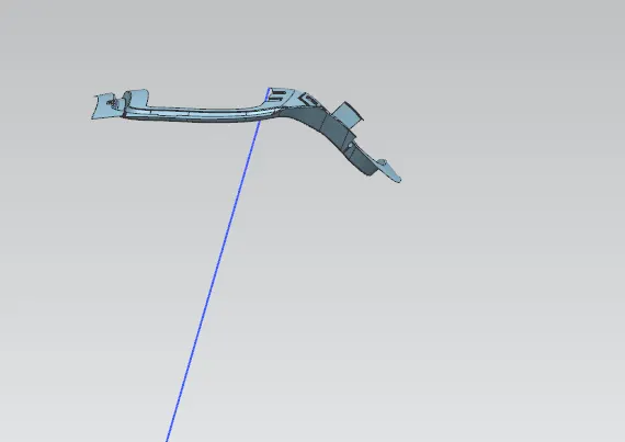
After that we have to create Sealing Flange by offsetting the outer panel to the specific distance.
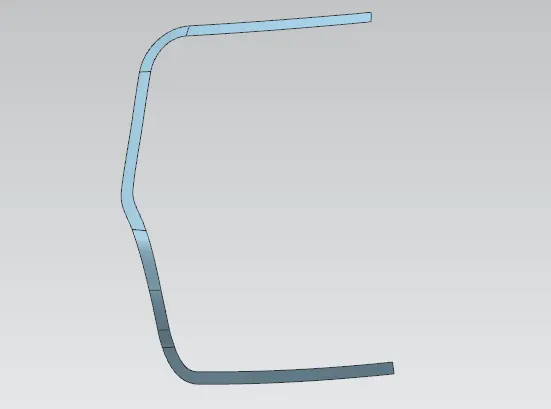
Then we will be creating the Back door inner panel flange by offsetting the outer surface at a distance considering the sheet thickness and thickening direction.
Then created the connecting flange to join the inner panel and sealing flange.
Then for the windshield panel mounting, windshield panel is created and joined with sealing flange.
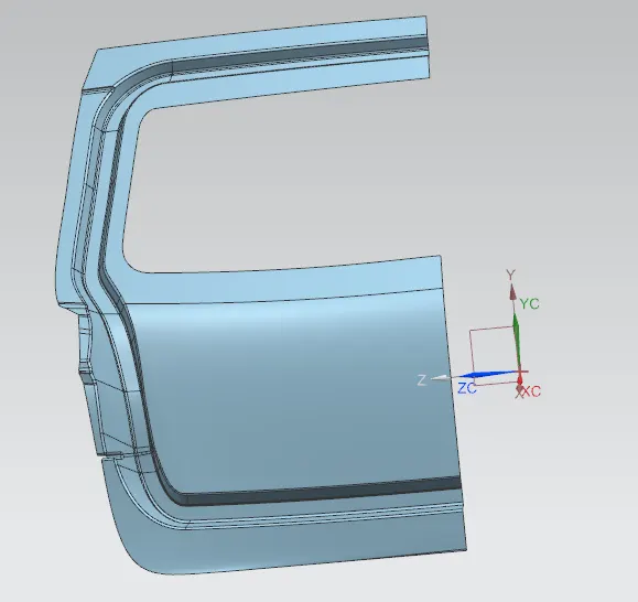
Then to improve the strength of the inner panel and to reduce the weight 'Y' type emboss and other cut-outs are created. Also, for Latch and Stricker mounting cut-out is created. This cut-out is also done on other side of the inner panel to maintain the centre of gravity of the Back door.
Parts Of the BackDoor
Inner Panel
Hinge Mounting Bracket ( LH & RH )
Gas Stay Bracket ( LH & RH )
Wiper Motor Support Bracket
Latch
Latch Reinforcement
Hinge reinforcement ( LH & RH )
Gas Stay Reinforcement ( LH & RH )
NNER PANEL
Inner door panel is a component which is use for strengthening the door assembly and it is one of the most important components on witch all accessories are mount like hinges, glass guide channel and gas stay.Back door inner panel is mounted with the the Roof.Inner is mounted with the outer panel with the help of hemming process.
- Materials used for the Inner panels are steels,Aluminum.
- For giving more strength to the inner panels by Adding extra reinforcements to strengthen the parts.
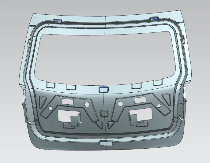
Above picture shows that the inner panel for Back door of a car.
In the Inner panel i used embosses,Outer panel and inner panel mounting area,space for Harness,Wind Glass Mount and fillets,No sharp corners.
Embossing
Embossing is a metal forming process for producing raised or sunken designs or relief in sheet material by means of matched male and female roller dies, theoretically with no change in metal thickness, or by passing sheet or a strip of metal between rolls of the desired pattern.
Materials commonly used in the metal embossing process include:
- Aluminum (All Alloys)
- Aluminum (T1/T2)
- Brass
- Cold rolled steel
- Copper
- Galvanized steel
- High strength, low alloy, steel
- Hot rolled steel
- Steel (All Alloys)
- Zinc
Cable Harness Gaps
I left some gap for Headlamp Harness and tailgate light harness cables.
Left some gap also dissipates the force when collision happens.
To much of cutting the inner panel leads to weaken the panel.
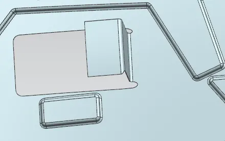
I provided two mounting Flanges for mounting the inner panel with outer stylish panel.
Two flanges is wnough strength for holding the outer and inner panels with the help of sealants.
In between inner panel and outer panel we providing sealants.
MASTIC SEALANTS
A mastic sealant is a type of liquid sealant that cures in an elastic state, thus making it flexible while holding the bond of the surfaces that has attached together. It adheres to just about any material making an all-purpose type of sealant.
- The main purpose of the outer panel is for the aesthetic looks. Thus we cannot use bolts or welding. This has to be done with the help of the hemming and mastic sealants. Mastic sealants are elastic compound that behaves like the rubber. It is placed between the outer and inner panel. Initially is it in paste form, but after the hot furnace bath it gets hardened thus joining the outer and inner panel. Mastic sealant has the tendency to increase the strength of the panel and has influence of 80mm diameter.
PROS
- One positive characteristic of mastic sealant is that it has a very smooth exterior while keeping its rigid form underneath.
- Surfaces do not have to be primed when using this type of sealant, and although applied thick, it adheres smoothly to any surface. It is important that the area to be joined or sealed be clean and dry, just like any other sealant on the market.
- Mastic sealant may be used outdoors as well because of its waterproof quality. It can be applied on rain duct leaks outdoors, for example.
- It is also favored for areas under high or low temperatures such as heater vents or drier vents and contains ultraviolet inhibitors to make sure that it is protected from damaging effects of the sun that will often weaken other types of sealants. That makes it a good choice for use on roofs, or any surface that is constantly exposed to sunlight. Most mastic sealants will also work well with metal because they do not corrode over time.
- it functions well in areas with mild vibration and heat, like heating ducts.
CONS
- Mastic sealant is not recommended for areas that have too much joint movement, or anything that will be moved a long length.
- It works well with constant pressure on it, but not constant movement.
- It also works best when applied thickly and is not recommended if only a thin layer is needed such as touch ups. Another sealant is a better choice for those types of repairs.
DRAFT ANALYSIS:
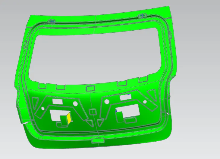
Draft analysis of inner panel is carried out through the tooling direction only.Only the green areas are acceptable and i worst cases yellow regions are accepted but the blue and red regions are never accepted.
The draft angle for aluminium casted panel is 2 to 3 degrees is enough but if it is steel then the angle is more than 7 degrees.
In this project i considered it as steel and used 7 degrees as draft angle and direction is choosen as tooling direction which is the deep drawn direction.
Hinge Reinforcement LH and RH:

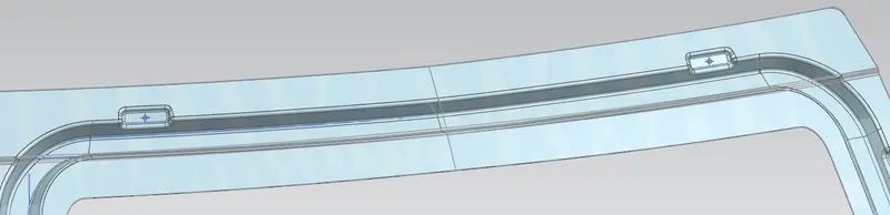
Gas Stay Reinforcement LH and RH:

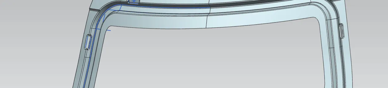
Wiper Hinge Reinforcement:
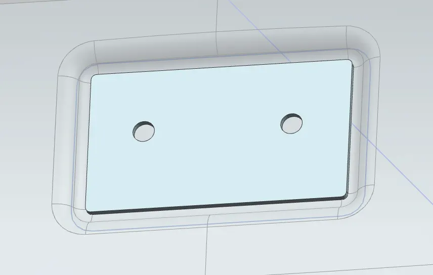
Latch and Striker Reinforcement:
Position of the hinge and Striker.
The hinges should be positioned on the hinge tentatively such that they lie on the same plane. The position of the hinge can also be decided based on the carry-over study.
From the axis of the hinges create a midpoint, from that midpoint draw a circle with a radius from the midpoint to the center of the striker. The circle created is called the trajectory circle. With the trajectory circle, it is to be checked that the striker is tangent to the trajectory circle if not then the position of the hinge should be moved accordingly such that the striker is tangent to the trajectory circle.
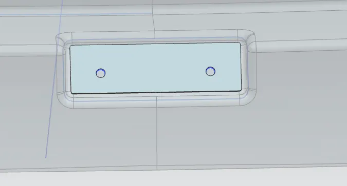
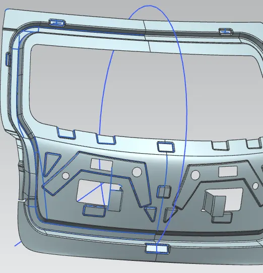
This is done because the latch where the striker strikes and locks the hood is positioned with respect to the trajectory circle. If the striker is not positioned accordingly then there will be difficulty in locking the back door.
Note: For all the closure components the position of the hinge and hinge axis is important and it influences the position and orientation of the striker.
Back Door Assembly
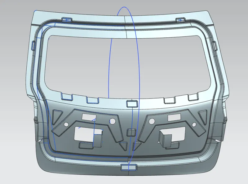
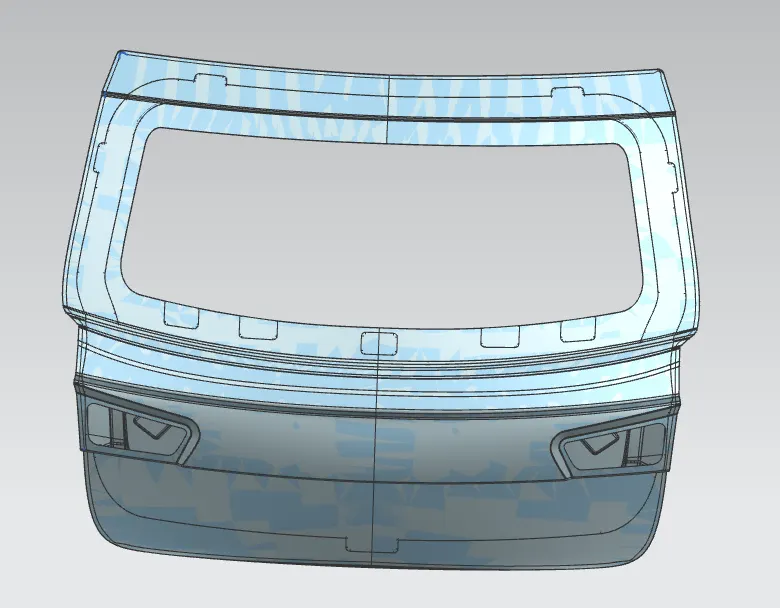
Conclusion:
The back door assembly is modeled following the engineering standards from the given styling surface.
1. Sealing Flange of length 25mm is maintained throughout.
2. Thickness for the reinforcement is 1.5mm.
3. Emboss are drawn with respect to the tooling axis so that they clear the minimum draft angle.
4. Corner relief is given to prevent unwanted deformation of the sheet metal at the corners while hemming.