Design, Modelling, Assembly and Rendering of American Chopper using Solidworks
INTRODUCTION
Choppers evolved from bobbers in the 1940's and 1950's. The term "chopper" simply means to chop parts off of or modify a motorcycle, however over the years it has come to represent a particular style of modified motorcycle, usually with a raked and extended front end, lowered rear suspension or no rear suspension, tall handlebars. The chopper was originally based on land speed record motorcycles and drag racing motorcycles, which had raked front ends, lowered suspension & frames, narrow front tires, small gas tanks and wide rear tires for traction. Originally it was a motorcycle version of the hot rods and lakesters from the 1950's.
OBJECTIVE
The project is to sketch and build a American chopper bike using solidworks.
PROCEDURE
1 - Designing of all parts of bike.
2 - Assembly of all designed parts.
3 - Sketch Decals
4 - Setting up Cameras and scenes
5 - Rendering
DESCRIPTION
Designing of all parts and components of the chopper are as follows.
- Transmission Belt
Transmission Belt in bikes are generally used to offer noise-free, smooth transmission for long distance riding. Since comfort, smoothness and less maintenance is more important here as compared to performance or fuel efficiency, the belt drive system lends itself well to the application. It is a loop of flexible material belt running over the pulleys or sprockets to link two rotating shafts for transmission of power from engine to gearbox.
Tools and features used to model belt are Sketch, trim, extrude and fillet. Two circles are sketched apart and then are joined by the line tangentially. The inner part of circles are trimmed and the whole sketch is extruded. Fillet the borders for smooth transmission.
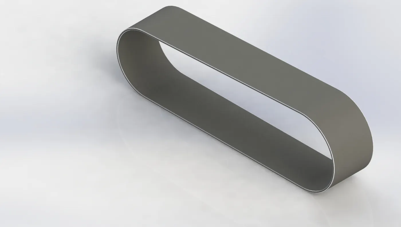
Transmission Belt
- Kick Stand
The Kickstand is usually a simple metallic part that touches the ground and allows the bike to stand.
Tools and features to model kickstand are sketch (2d drawing), Extrude , Extrude cut, loft, trim, dome, fillet. Kickstand model consists of lofted profiles with dome at one end.
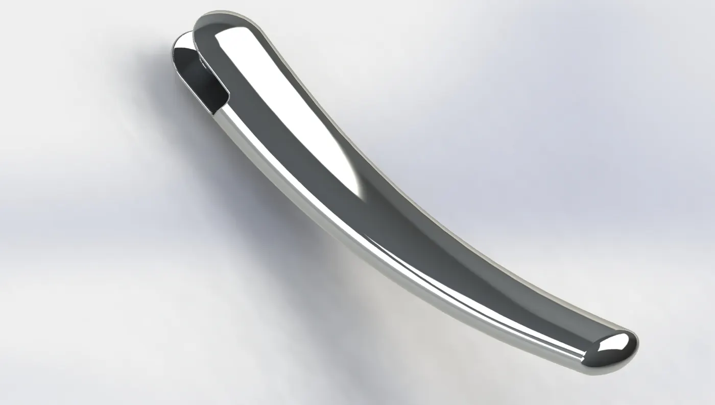
Kickstand
- Front Fender and Rear Fender
Front fender is located over the front wheel and Rear fender is located on rear wheel. Fenders are used protect the rider and some parts from the debris, mud, water etc. which are thrown by the tyres while riding.
Both front fender and rear fender are basically modelled with similar method. Tools and features use to model are sketch, Revolve, split, surface trim, extrude cut, shell etc.. Firstly, the sketch is revolved and then it is splitted or surface trimmed to get the required size. Then other features like fillet are used to avoid the sharp edges. Lastly shell is performed to get a convex hollow part. Only the shape and size vary in both the fenders .
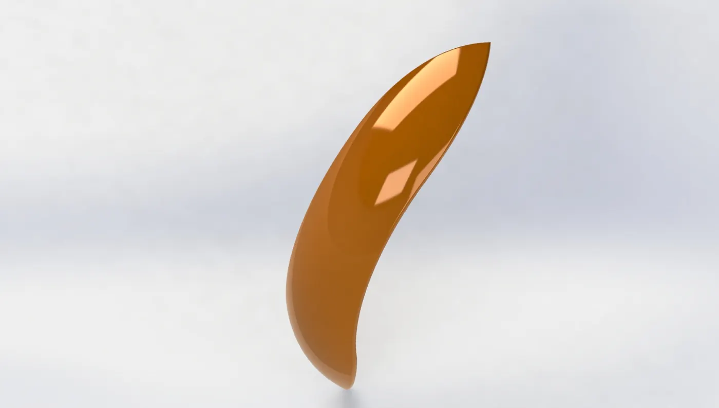
Front Fender
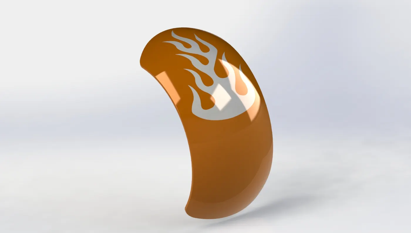
Rear Fender
- Chain
Chain is used to transmit the power from engine to the rear wheel. The chain has rollers which are moveable and can rotate.
Tools and features used for modelling chain are sketch, extrude, pattern. But first the pin/roller and the plate should be made and then the path or profile should be made over which the roller and plate link will be patterned. The profile is made by various curvature. So as the curvature varies the pattern feature is repeated until the end of the link matches with the start. After using pattern feature check whether the links are properly matched at the end, if not, Copy and constrain the link between last and first link.
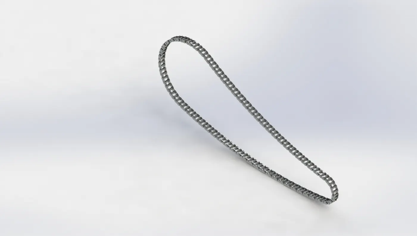
Chain
- Oil tank
Oil tank is just a hollow box in which oil is stored. This oil is then used by the engine for smooth working.
Modelling of oil tank is simple. Tools and features used are Sketch, surface extrude, surface trim, surface knit, shell and fillet. Basic process to design is sketching the required shape, then make a solid body by extruding, trimming unwanted and knitting. After solid shape is formed use shell feature to make it hollow inside. Fillet the edges for removing corners.
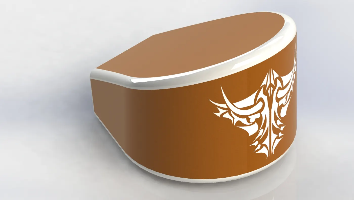
Oil Tank
- Pedal
Pedal is a part on which the riders rest his foot, and is also use to change the gear in manual bikes.
Tools and features used are sketch, extrude, revolve, dome, pattern, fillet, chamfer. First draw the basic shape of pedal in sketch and then extrude it. Then sketch the circles for the part where rider rest its foot. Use revolve, chamfer and fillet for aesthetic look and smoothing of part.
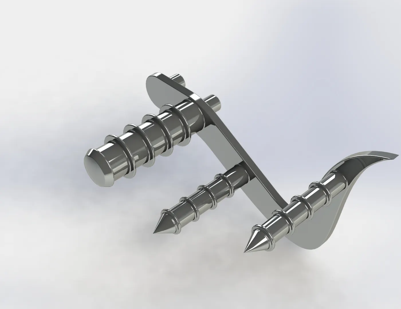
Pedal
- Front wheel and Rear Wheel
Wheels are circular part attached to rim and are filled with air. In this project front wheel is smaller than rear wheel. Brake pad and calliper is attached to the Front wheel and Rear wheel. Chain sprocket is attached to only rear wheel.
Tools and features used are extrude, extrude cut, revolve, revolve cut, pattern, fillet, mirror, chamfer etc. The front and rear both wheels are modelled similarly. First the rim and hub is made by using revolve feature and then for aesthetic look other features are used. Then the webbing of rim is done. After that the brake pad, calliper and sprocket is made.
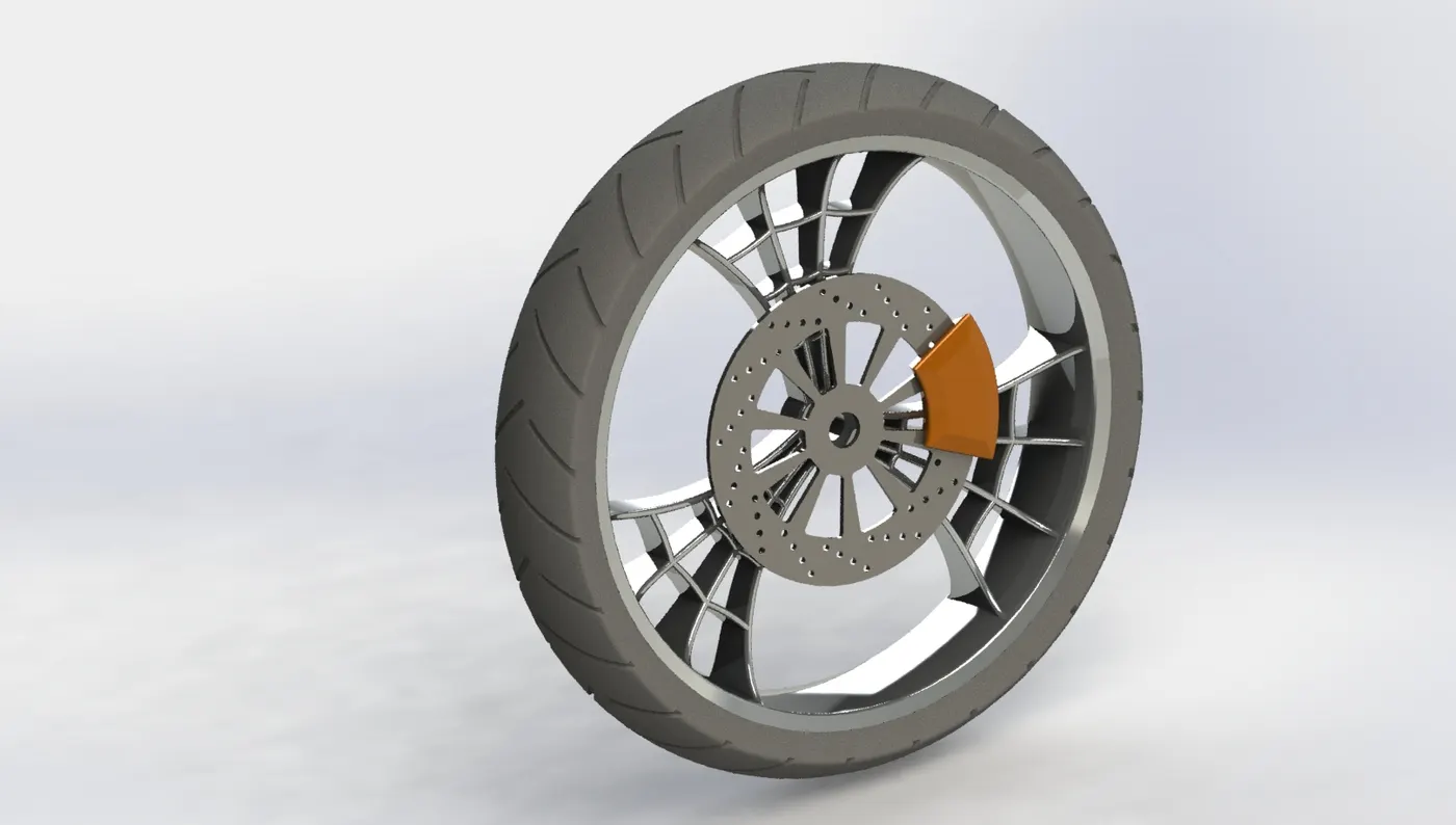
Front Wheel
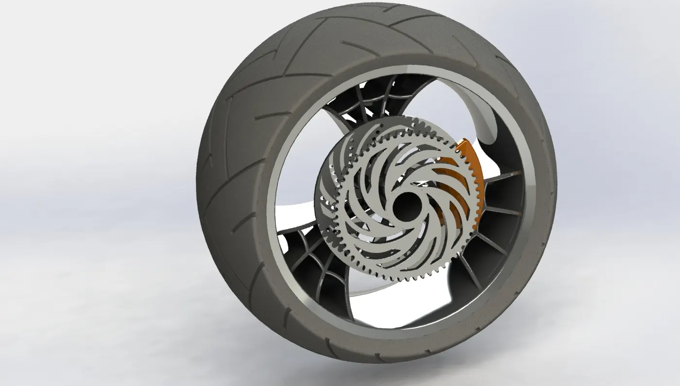
Rear Wheel
- Front fork
Fork holds the front wheel and is fixed to the chassis. American choppers have long forks and at extreme angles.
Tools and features used for modelling are Sketch, Extrude, revolve, sweep, Shell, Dome, mirror, pattern, projected curve. First model one fixed rod by using revolved feature. Then model the half of triple tree by extruding and then patterning the counterpart. Then part of the axle is extrude and revolved to model the light. After this the handle is made by sweeping the circular sketch along the projected curve. The grip, brake and brake wire are model similarly with the reference of projected curve. Everything modelled should be then mirrored and combined.
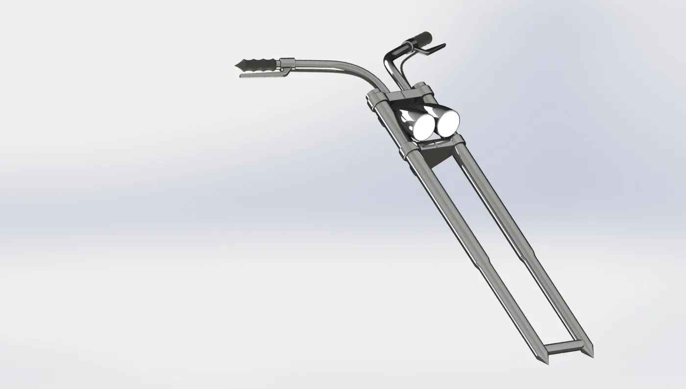
Fork
- Chassis
Chassis is the most vital part of the vehicle. The strength of the bike is decided by the chassis. Suspension, seat, handles, wheels etc. are attached to chassis.
Chassis is mainly model using curves. Tools and features used are Extrude, Extrude cut, Revolve, Revolved cut, Sweep, Dome, project curve, mirror, fillet, chamfer etc. Modelling starts from the tubes of chassis. Front side tubes and back side tube are modelled using projected curve. Then the back side plate is made. Similarly all tubes are created then the bottom plates are extruded from one tube to opposite tube. Then pedal is made using offset extrude. After all this is done fillet, chamfer, mirror etc. are done for creating final chassis model.
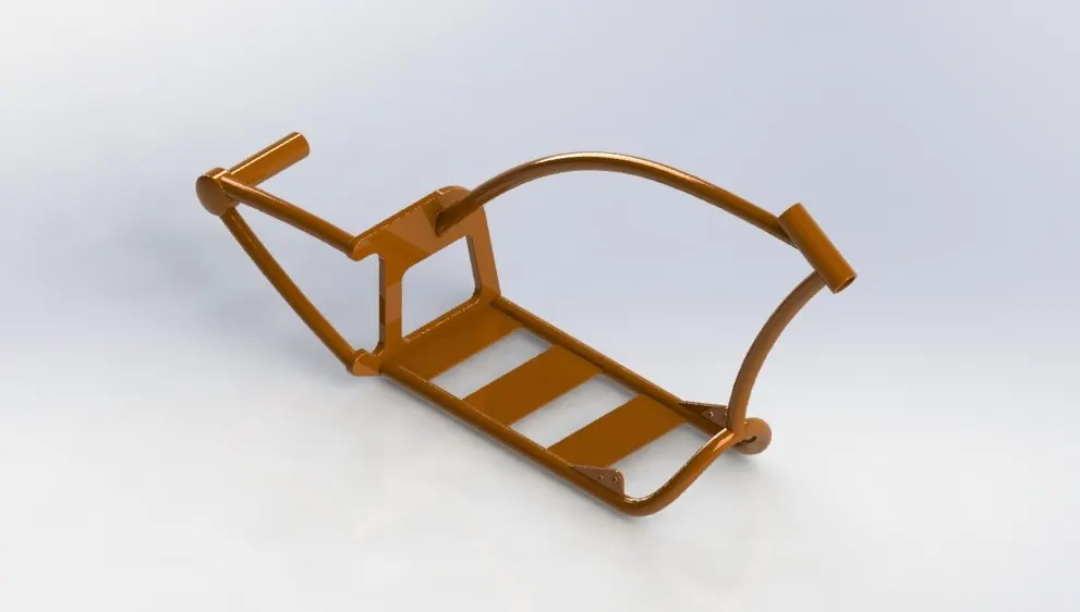
Chassis
- Engine
Engine is a powerhouse of vehicle. It converts chemical energy into heat energy and this heat energy does the work. This work done is transferred to rear wheel through chain and sprocket.
Tools and features used for modelling Engine are Sketch tools, extrude, extrude cut, chamfer, Projected curve, pattern, fillet, dome, sweep, chamfer etc. The modelling start with the gear housing and starter motor housing. This housing is made with the use of basic sketch tools and extrude feature. Then cylinder is made of polygon shape and cuts are made to show fins for cooling. The cylinder is then mirrored. After mirror is done the pipes are made which connects the cylinder using sweep feature. Then exhaust is made by using projected curve and sweep feature.
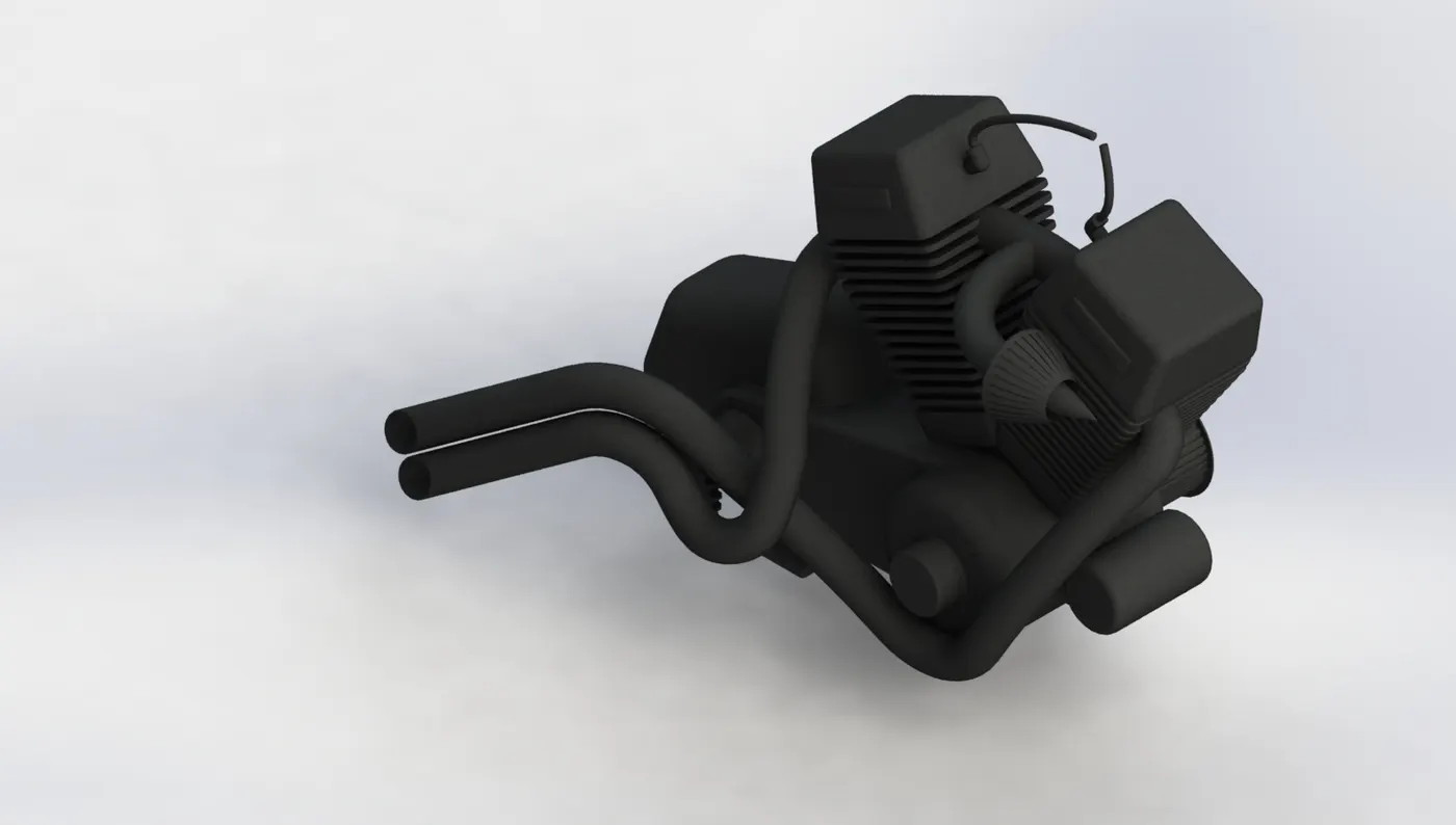
Engine
- Gas tank
Gas tank is the fuel tank which stores fuel and is of complicated shape. As it is top of the bike it is made stylish with great aesthetic look.
Modelling of gas tank is made using sketch tools, surface sweep, surface loft, Shell, surface knit, mirror, extrude cut etc. The start of modelling is from the basic shape of gas tank which is created using surface sweep and other tools. Then the end of gas tank which is bend in triangular shape is made using projected curve and surface loft. Similarly, the side surface is created using projected curve and surface loft. Then the seat is created by extruding. Then the bottom surface in created and closed tank is made. Then the cut-out is made for the tube of chassis. Finally the fillet is created to avoid sharp curves and then shelled to create hollow part inside.
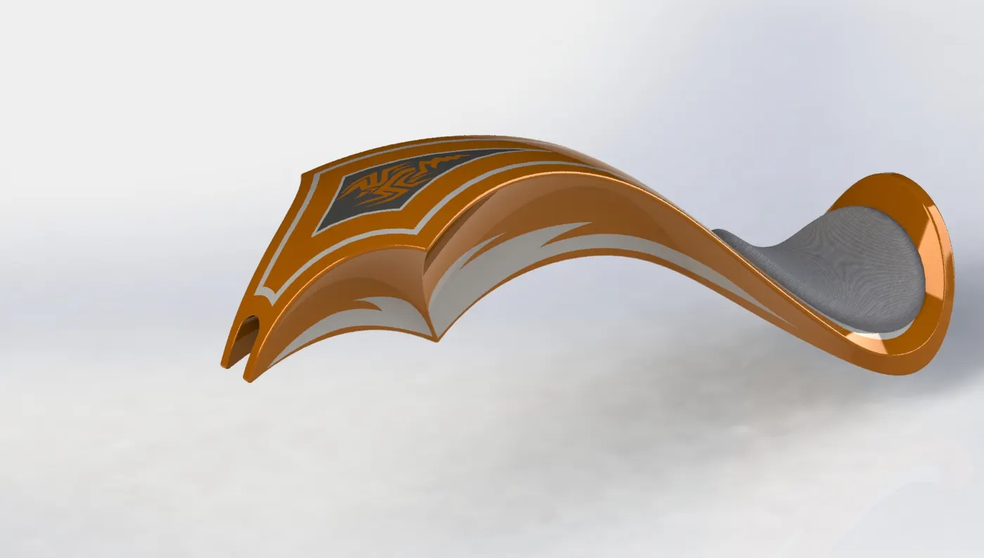
Gas Tank
Assembly
First step of assembly is done by adding all the created components into the assembly space. Then by making the vital part fixed in the space in this case the Chassis. Once the chassis is fixed then all the other parts are matted together using different types of mate like coincident, concentric, distance, colinear, width etc. Once all parts are matted and assembly is done, rendering can be started.
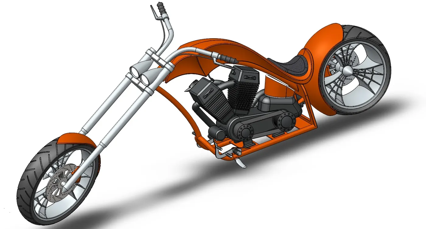
Assembly of Chopper
Rendering
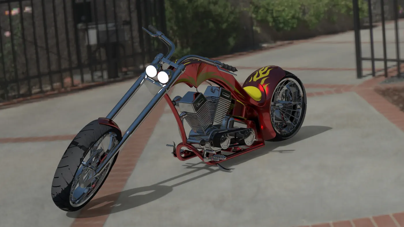
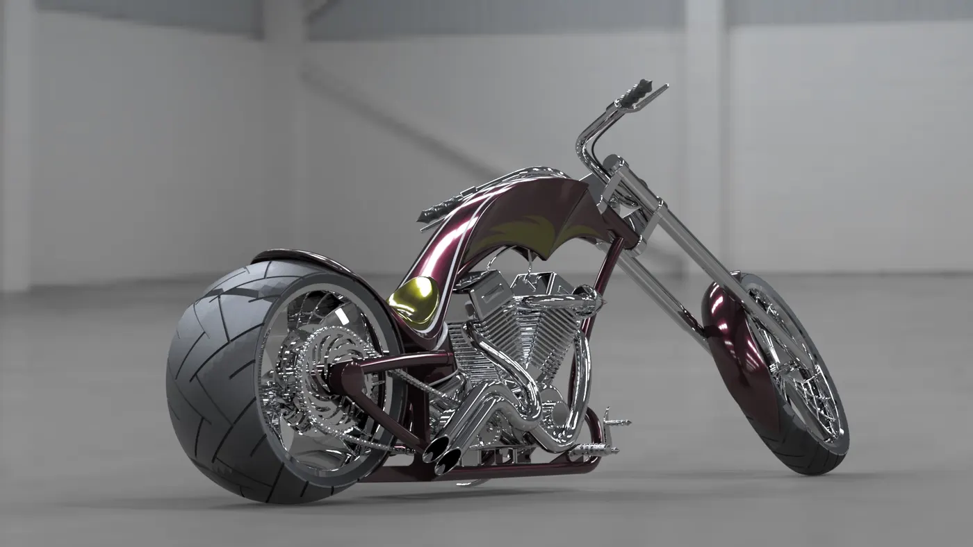
Photoview 360 or Solidworks visualize is use for rendering the models. Rendering is done to make the object realistic. Adding decals, Scenes, Environment, Light setup, appearance of any material etc. are rendering process. In this project, to render the bike a Plane white scene is added with daytime environment to obtain reflections of the parts. Different material are applied to the each object to give realistic appearance. Then the camera setup is done which shows the view from angle set in the camera. Add decals to the Rear fender and gas tank and proper mapping is carried out. Check for appropriate scenes and proper light setup to make the chopper realistic in final rendering.
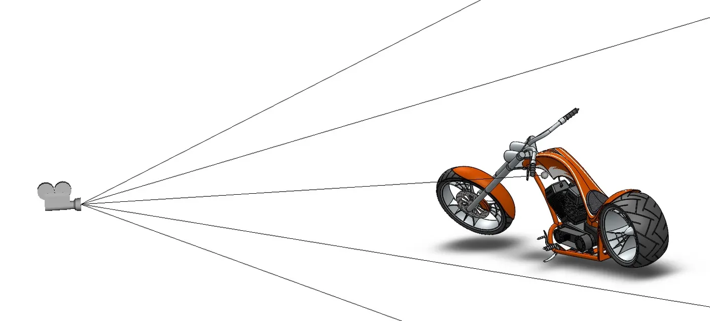
Camera Setup
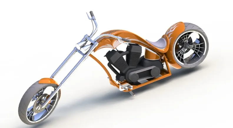
Adding Decals
Conclusion
In this project, Each part is designed individually and then given the required and suitable appearance. Then all parts are assembled to create a model of American Chopper with renders to get realistic look.