Advanced Sheet Metal Design Using NX Cad Challenge_8_Flattening and Forming.
Project Objective: In this Project, I am going to Explain Natural Data Files & Its Types and Design Complex Sheet Metal Parts using Flattening & Forming Commands in NX-Cad.
01.About Neutral Data File:
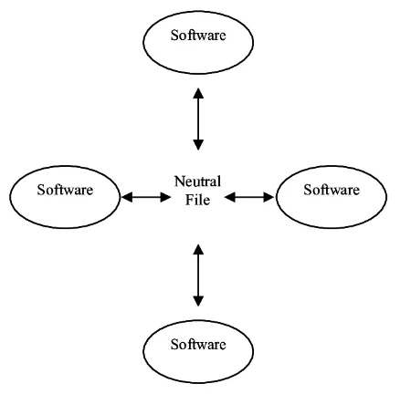
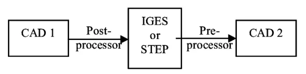
A Neutral file is a formatted text file containing information about parts and assemblies created in Siemens NX. The Siemens NX application formats part geometry data so that other software systems can easily read it and a wide variety of applications can use it. You can create neutral files from parts and assemblies.
01-1.Types of Neutral Data File:
- STEP
- QIF
- 3D PDF
- IGES
- STL
- ACIS
- PARASOLID
Stereolithography Files (File Extension: .STL)
USES:
STL files are universal 3D formats that focus on surface geometry and shapes but not for colors, textures, or other model attributes, which is good for rapid prototyping, 3D printing, and some CAM software.
However, it uses a triangulated mesh surface which is acceptable for visual representation, but not workable in CAD systems since most work in solids.
When complicated CAD is not required, STL files are acceptable in most basic situations.
PROS:
- Widely supported file format.
- Popular for 3D printing.
CONS:
- Describes surface geometry only — it is not precise B-rep.
- Very simple data model — no support for color, surface grouping, or even user-defined attributes.
IGES(file Extension:IGS,.IGES
USES:
Mostly used for surface geometry (although it can support solid models) and design work. Can often get translated with gaps between surfaces, missing faces, and even surfaces with wrong orientation. So it’s recommended to go with STEP or QIF or have a tool for repairing bad geometry and stitching surfaces.
PROS:
- It’s your grandfather’s CAD file.
- Ubiquitously supported.
CONS:
- IGES doesn’t support solid models, just surface geometry.
ACIS (File Extension: .SAT)
ACIS files are 3D solid and surface CAD files from Spatial, a Dassault Systemes division. It is a geometric modeling kernel compiled in C++ and used in CAD, CAM, CAE, and CMM.
PROS:
- The internal modeling language used by lots of downstream software.
CONS:
- Not a standard data format.
- Usually requires a custom translator to export to ACIS.
- Doesn’t support semantic PMI in any standard way.
PARASOLID (File Extension: .X_T)
USES:
It represents wireframe, surface, solid, and general non-manifold models. Most Parasolid files migrate 3D solids and/or surface data.
PROS:
- The internal modeling language used by lots of CAD and downstream software.
- Great CAD export option if you use NX or SolidWorks.
CONS:
- Not a standard data format.
- Uses some proprietary blend recipes, making some data inaccessible to non-Parasolid modelers.
02. Design Complex Sheet Metal Parts and apply Flattening and Forming Commands.
01. About Complex Sheet Metal Parts:
Sheet Metal is metal formed by an industrial process into thin, flat pieces. Sheet metal is one of the fundamental forms used in metalworking, and it can be cut and bend into a variety of Shape. Countless everyday objects are fabricated from sheet metal. Thicknesses can vary significantly, extremely thin sheets are considered foils pr leaf, and pieces thicker than 6 mm are considered plate and Steel or structural steel.
There are many different metals that can be made into sheet metal, such as aluminum, brass copper, steel, tin, nickel, and titanium.
Sheet metal is used in automobile and truck(lorry) bodies, airplane fuselages and wings tables, roofs for buildings (architecture), and many other applications.
Nx Sheet metal application has advanced features that can quickly convert solid models to sheet metal components, and create sheet metal parts that enclose other components. these advanced features create a surface model from a generic solid body by ripping edges, cleaning up geometry, and converting to a sheet metal body.
02. Part Navigators:
Sketch
Tab
Flange
Normal cut-off
Dimple
Hole
Unbend
Rebend
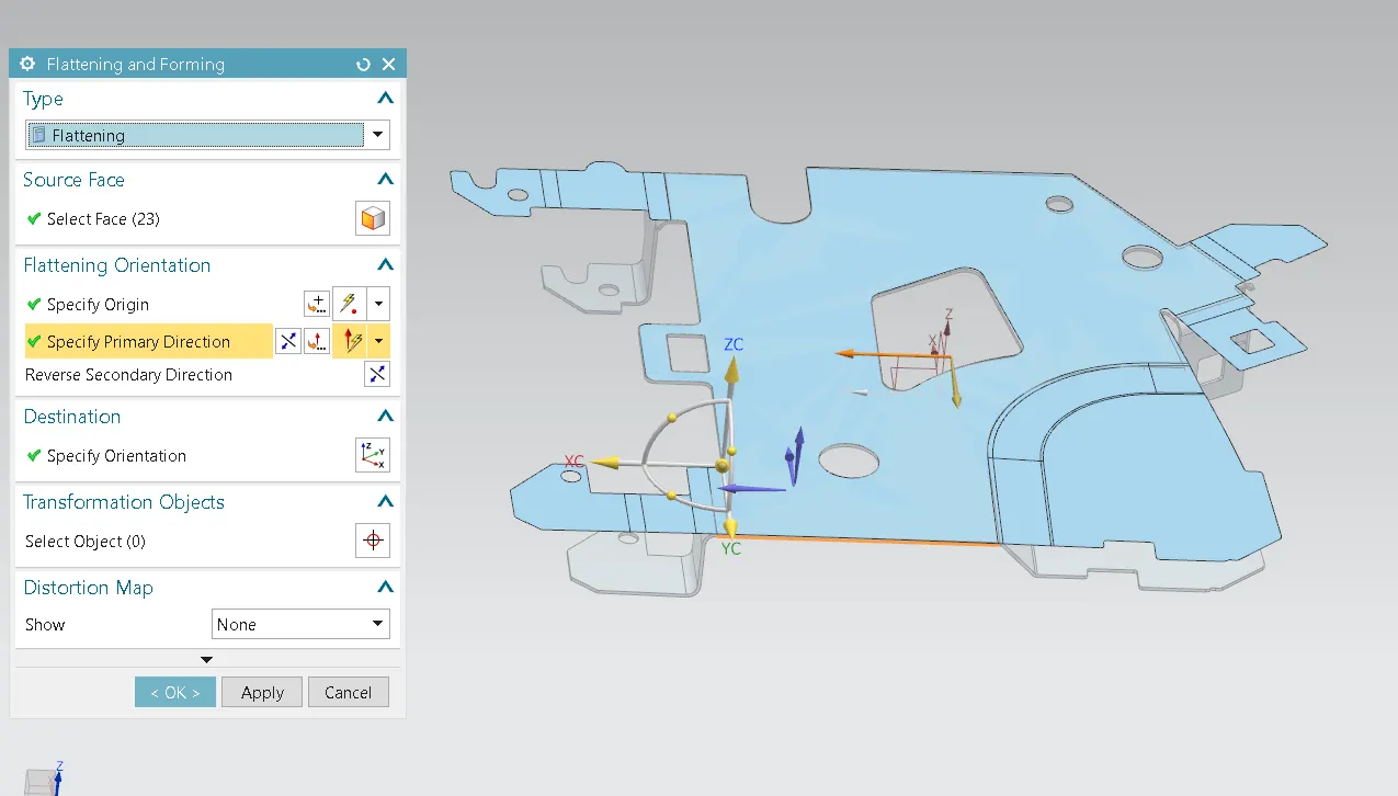
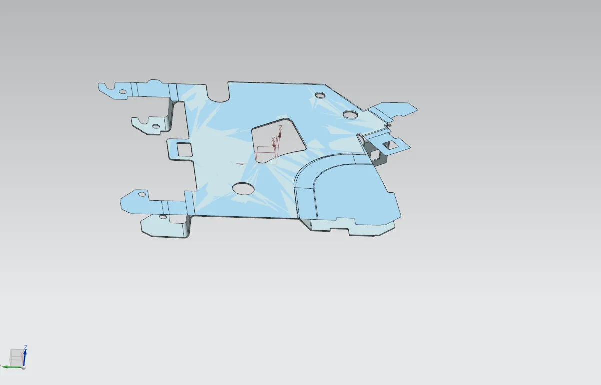
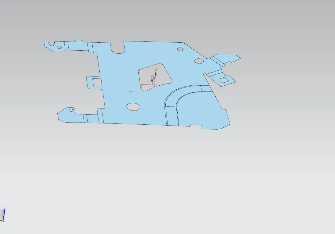
Flattening & Forming
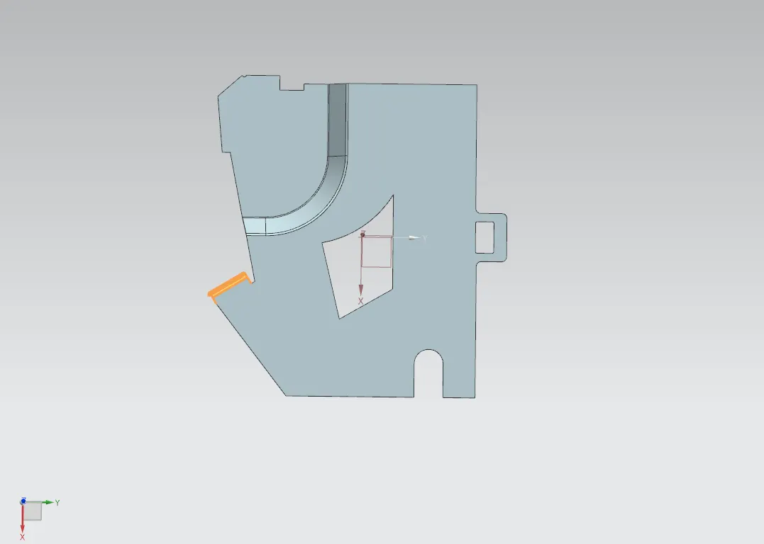
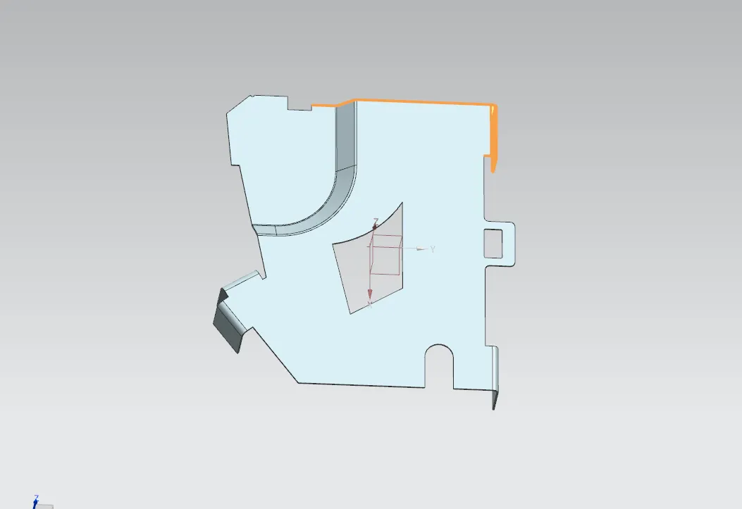
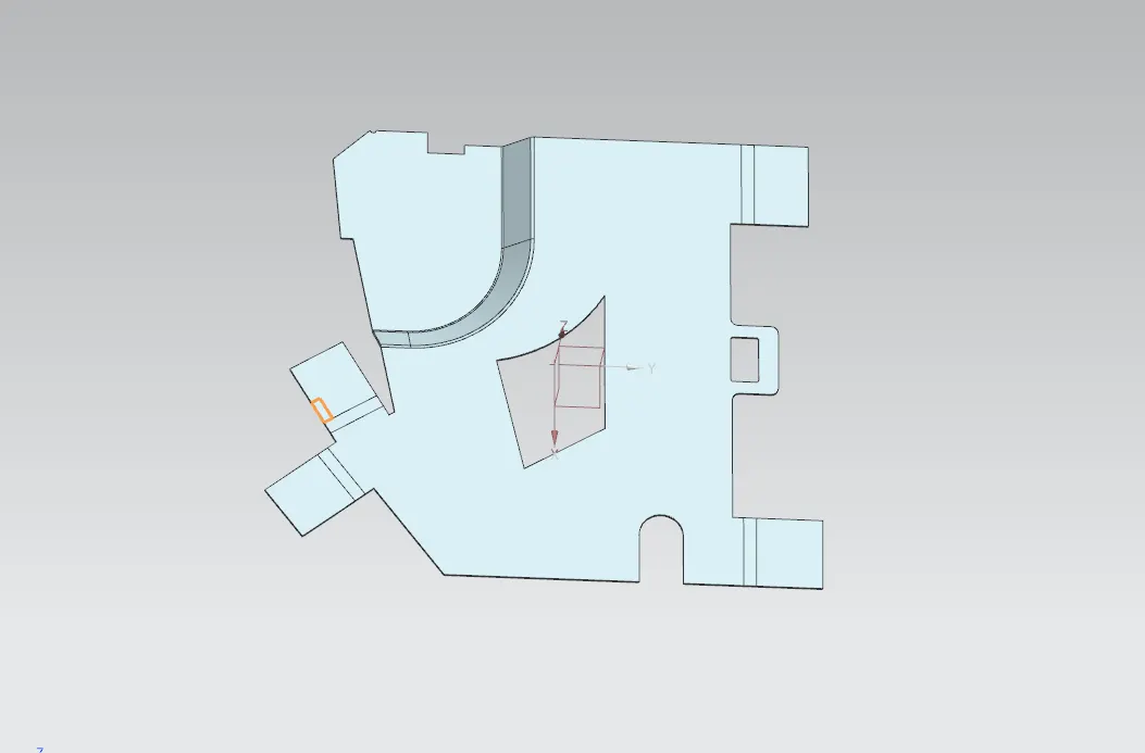
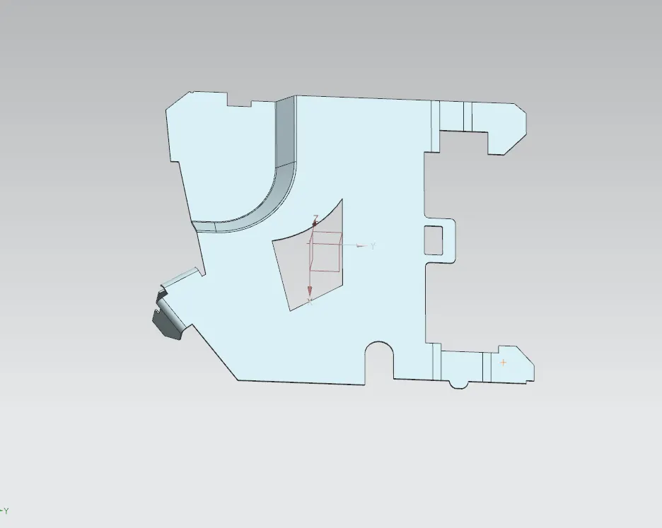
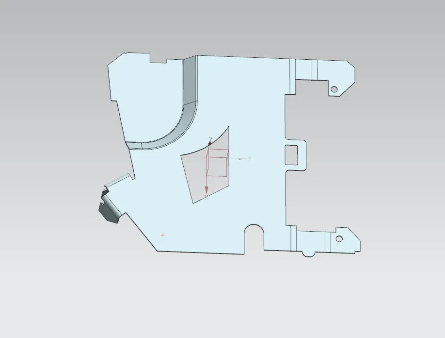
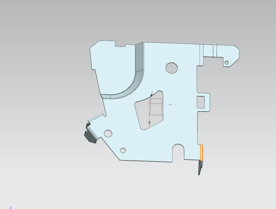
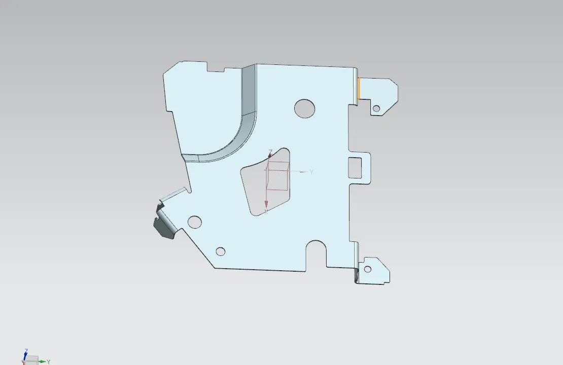
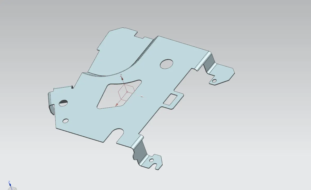
03. Design Process of Complex Sheet Metal Parts and Views:
04. Flattening and Forming:
05. Flate Patten:
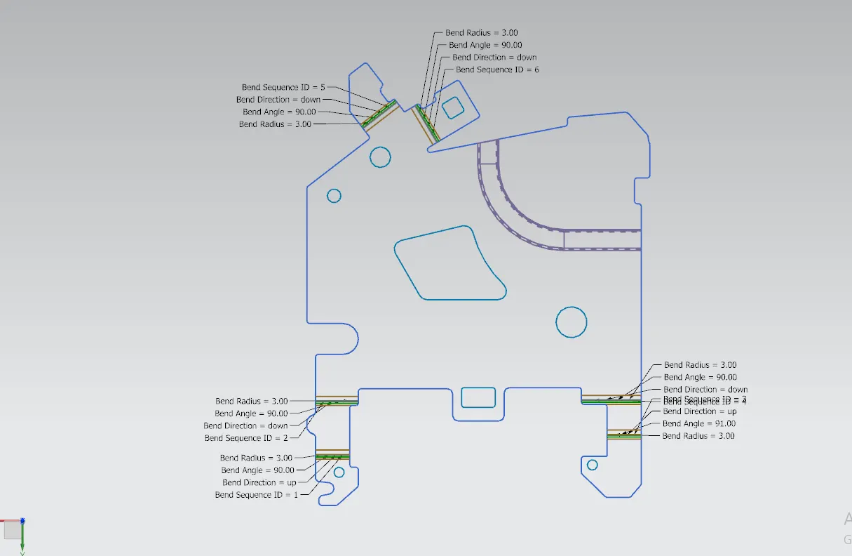
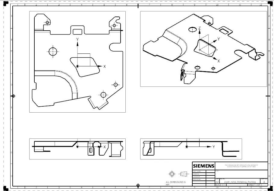
06. Drafting Views:
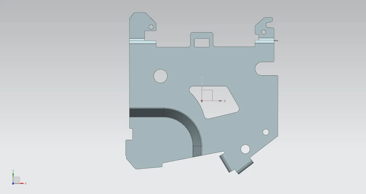
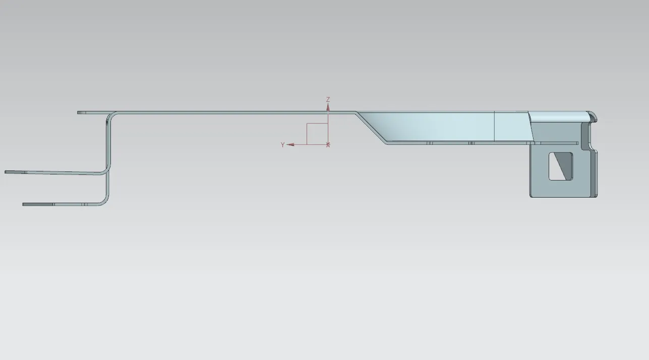
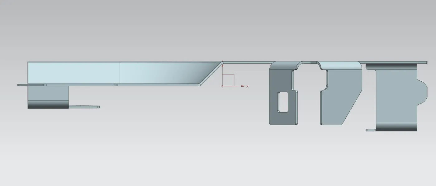
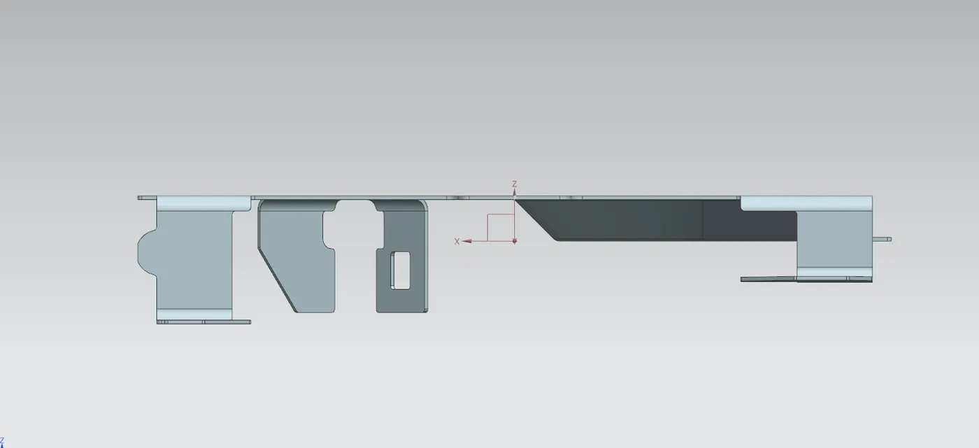
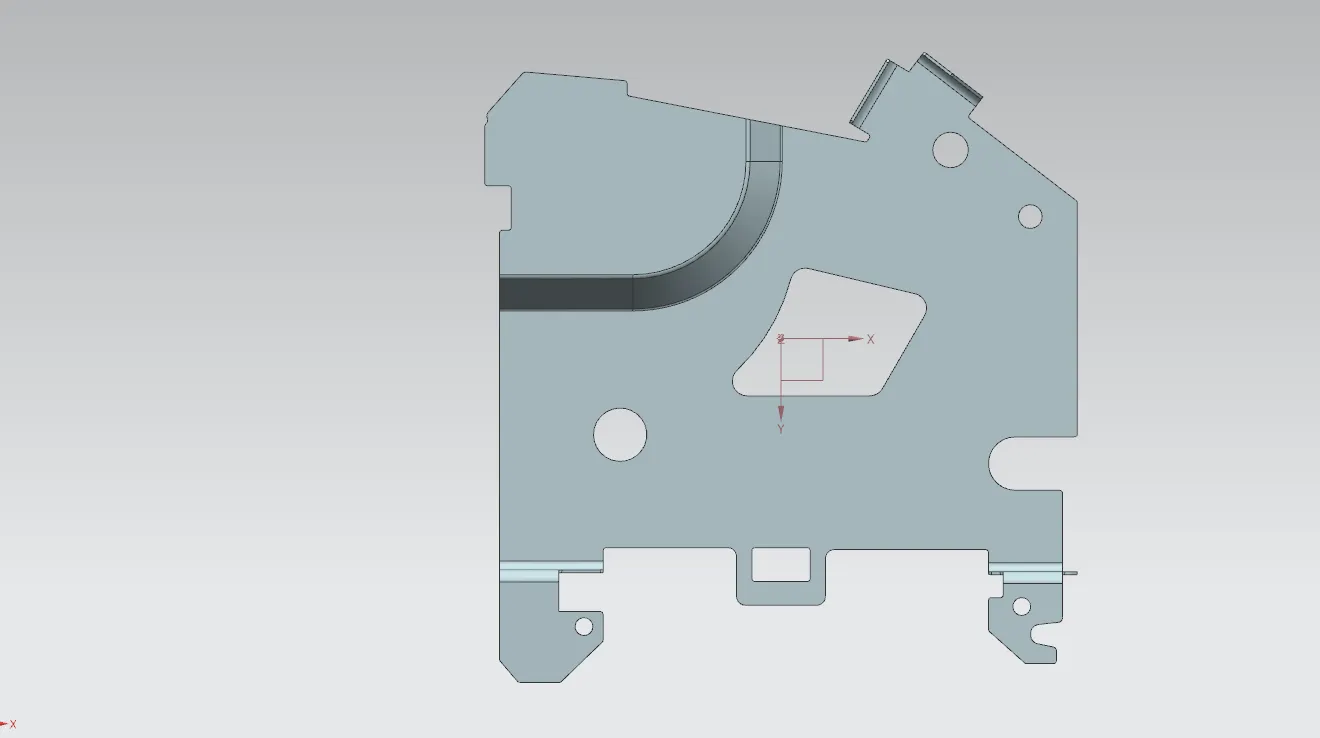
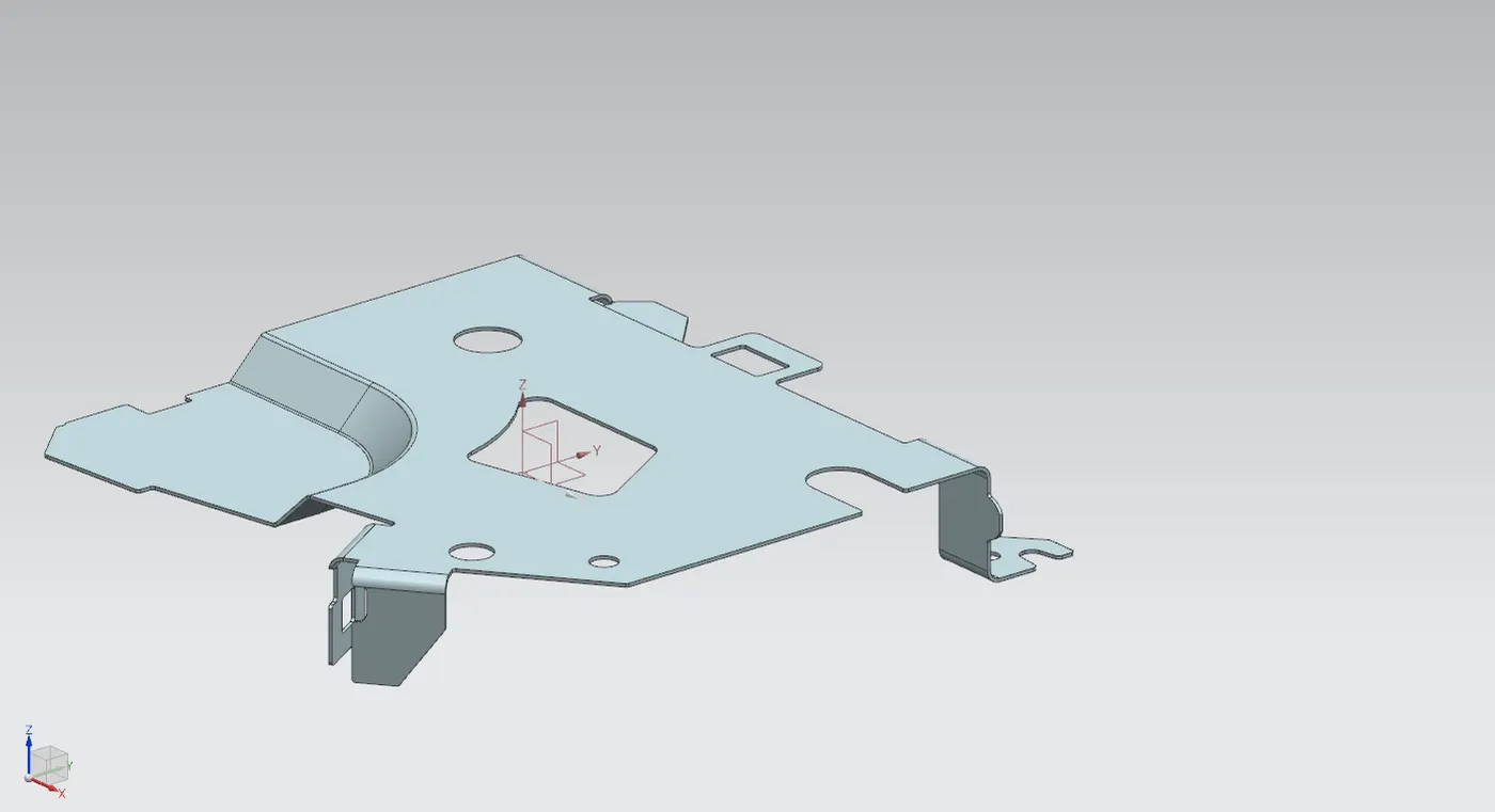
07. Final Design:
08. Google Drive Model Link:
https://drive.google.com/file/d/1_lTbEVVDpkDQFO3RfvVXh8qSgsodamS-/view?usp=sharing
09. Conclusion:
Thus, I have Studied about Natural Data Files & Its Types use in Nx-Cad and Designed the Sheet metal complex parts using Nx-Cad
Thanks & Regard
Rajnish Kumar