Cyclone Seperator Challenge
1.CYCLONE SEPARATOR CHALLENGE:
AIM:
To perform analysis on cyclone separator and calculate the separation efficiency and pressure drop by varying particle diameter and particle velocity.
INTRODUCTION:
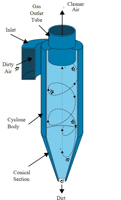
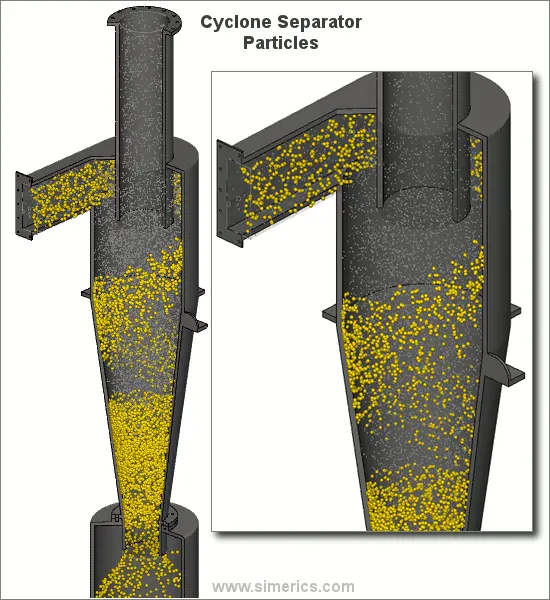
Cyclone separator or cyclones are the devices that employ a centrifugal forces generated by a spinning gas stream to seperate particle from carrier gas.
Cyclones are the devices built to remove particulate matter i.e., to seperate dust from gas or for product recovery. Not very effective on large particulate matter.They are inexpensive.
THEORY:
Cyclone separator is a pollution control devices known as precleaners which generally removes large pieces of particulate matter larger than 10micrometer.
The principle is the driving force behind cyclone separation is centrifugal force and the difference in specific gravity between the particle and the carrier gas
Some assumptions are common to all these models and can be consider reasonable enough to obtain a good compromise between accurate predictions and simplifications of equation.
- Particles are spherical.
- Particle motion is not influenced by presence of neighboring particles.
- Radial velocity of gas equals to zero.
- Radial force on particle is given by stoke's law.
EFFICIENCY CALCULATION:
Separation efficiency = (Trapped particle) / (Number of particle tracked)
PRESSURE DROP:
Pressure drop = Inlet pressure - Outlet pressure.
EMPIRICAL MODELS USED TO CALCULATE CYCLONE SEPERATOR EFFICIENCY:
1. Iozia and Leith model(1990):
Developed based on force balance.Modified version of Barth model(1956)
Assumptions:
Particle carried by the vortex endures the influence of two forces. i.e., centrifugal force Z & flow resistance W
Later core length z_c and core dia d_c were added for Iozia and leith model which is derived based on the statistial analysis of experimental data of cyclone with diameter of 0.25m.
`η = 1/(1 + (dpc + dp i)2)`
`eta`= Fractional particle collection efficiency
`d_(pc)`= diameter of particle collected with 50% efficiency in m
`d_(p i )`=diameter of particle in size range i(m)
2.Li and Wang model(1989):
Model includes particle bounce or re-entrainment and turbulent diffusion at the cyclone wall.
2D analytical experiment of particle discrete in cyclone is obtained.
Assumptions:
Radial particle velocity and radial concentration profile are not constant, for uncontrolled particles within cyclones.
Boundary condition with consideration of turbulent diffusion coefficient and particle bounce re-entrainment on cyclone wall are at
`η_i= 1 − exp{−λθ_1}`
where `θ1= (2π (S + L))/a`
Tangential velocity is related to radius of cyclone by uR^n= constant.
3. Koch and Licht Model (1977):
Theory recognised the inherently turbulent nature of cyclones and the distribution of gas residence time within cyclone.
Assumptions:
Tangential velocity of particle is equal to tangential velocity of gas flow. i.e., there is no slip in tangential distribution between particle and gas.
Tangential velocity is related to radius of cyclone by uR^n= constant.
`η_i= 1 − exp(−2((Gτ_iQ)/D^3(n + 1))^(0.5/(n+1)))`
where `G =((8K_c)/(K_a^2K_b^2))`
`n = 1 −(1 −(12D)^0.14/2.5)((T + 460)/530)^0.3`
4. Lapple model (1951):
Developed based on force balance without considering flow resistance.
Assumptions:
Particle entering cyclone is evently distributed across the inlet opening.
Particle that travels from inlet half width to wall in cyclone is collected with 50% efficiency.
`η_i=1/(1 + (d_(pc))/((d)^-_(p i)))^2`
where `d_(pc)=((9 µb)/(2π N_ev_i(ρ_p− ρ_g)))`
SOLVING AND MODELLING APPROACH:
GEOMETRY:
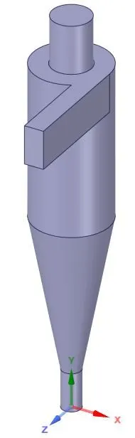
Carry out analysis model on fluid volume by extracting volume of edges.
BEFORE EXTRACTION AFTER EXTRACTION:

MESH:
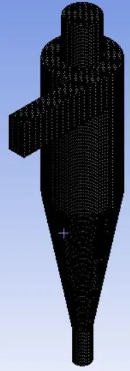
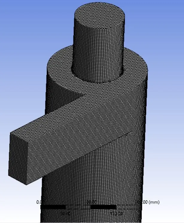
Body sizing has been made for given geometric model to be refined mesh and that to attract with main fluid domain that we mesh.
Named selection as Inlet 1 , Outlet 1, Outlet 2.
Structural mesh gives the best results, so cutcell meshing approach is used.
Element size = 6mm
Cell count = 499135
PREPROCESSING:
SETUP:
Steady state simulation is enabled as its time independent.
Model is in upright plane xy, such that gravity acts in -y direction. i.e., g= -9.81m/s^2
k-epsilon,RNG model.Because RNG enhances swirling flows.swirl dominated flows is enabled.
Here to remove particulate matter,method used is simulation using DPM.
In DPM,
Discrete
- Smaller particles interact with continuous phase.
- Discrete exchanges fluid mass,momentum and energy with continuous phase.
Uncoupled flow-Discrete phase will not have any interaction with continuous flow.
Coupled flow-discrete phase will have interaction with continuous flow.
Here small particles employedin cyclone seperator,it doesnot affects much.
Continuous
- Fluid flowing within fluid volume.
DPM interval - 10, It allows to control frequencies at particles attract.
Maximum number of time stepis to compute single particle projectory.
For steady state, time step given here is upto 6,00,000.
Specifying length scale and step length factor are to control time step.
Dividing length scale is with velocity of discrete particle and velocity of continuous particle.
Smaller value of time size gives accuracy.
Injection is created with anthracite material with varying velocities and diameter based on the cases.
Boundary Conditions:-
Inlet and wall:- Reflect
Outlet(Top):- Escape
Outlet(Bottom/dustbin) - Trap
Second order upwing method is more accurate spartial discontinuous for this type of problem.
Thus we have inlet/outlet , standard initialisation is done
Number of iteration = 600.
When calculation is done,particle history data file is exported to get datas of particle trapped, tracked,escaped and incomplete if any.
CASES GIVEN:
PART-1
Keeping velocity constant,varying diameter
| Velocity in m/s | Diameter in `mum` |
| 3 | 1 |
| 3 | 3 |
| 3 | 5 |
PART-2
Keeping diameter constant, varying velocity
| Velocity in m/s | Diameter in `mum` |
| 1 | 5 |
| 3 | 5 |
| 5 | 5 |
POST PROCESSING:
Particle history data file are imported to analyse the particles tracked,trapped and escaped particles.
Some of the particles are escaped at outlet 1 and few at outlet 2.
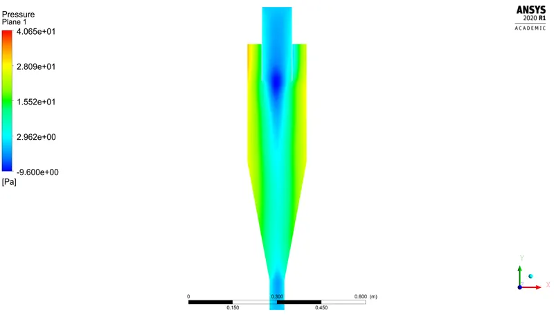
XY plane is created along the model to pressure drop.
Varying the dimension /cyclone seperator velocity to manage the efficiency outgoes.
Vortex core region are enabled to viewing particle activity.
Animation is made for visual purpose of removing particles of cyclone separator.
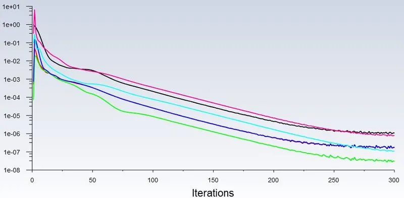
RESIDUALS:
Velocity = 3m/s Diameter = 1`mum`
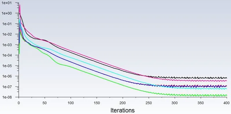
Velocity = 3m/s Diameter =3`mum`
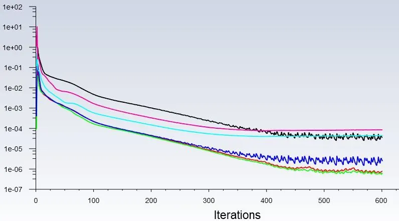
Velocity = 3m/s Diameter =5`mum`
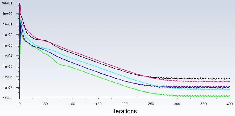
Velocity = 1m/s Diameter = 5`mum`
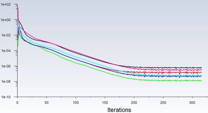
Velocity = 3m/s Diameter = 5`mum`
Velocity = 5m/s Diameter = 5`mum`
ANIMATION VIDEO:
Velocity = 3m/s Diameter = 1`mum`
Velocity = 3m/s Diameter =3`mum`
Velocity = 3m/s Diameter =5`mum`
Velocity = 1m/s Diameter = 5`mum`
Velocity = 3m/s Diameter =5`mum`
Velocity = 5m/s Diameter = 5`mum`
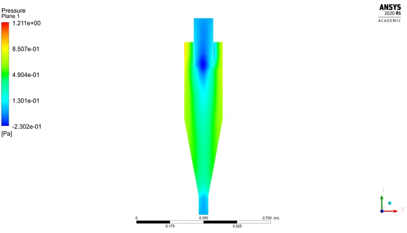
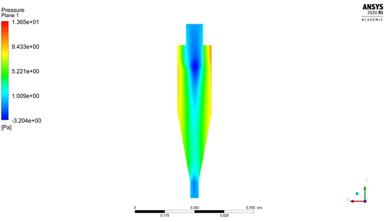
PRESSURE CONTOUR:
Velocity =1m/s , Diameter = 5`mum`
Velocity =3m/s , Diameter = 5`mum`
Velocity =5m/s , Diameter = 5`mum`
CALCULATION:
PRESSURE DROP = INLET PRESSURE - OUTLET PRESSURE
For case 1
Velocity =1m/s , Diameter = 5`mum`
Pressure drop = 1.17-0 = 1.14pascal
For case 2
Velocity =3m/s , Diameter = 5`mum`
Pressure drop = 12.67-0 = 12.67pascal
For case 3
Velocity =5m/s , Diameter = 5`mum`
Pressure drop = 37.3806-0 = 37.3806pascal
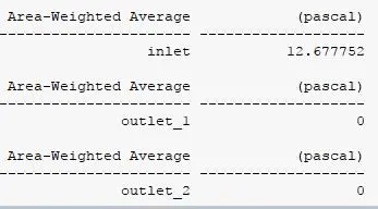
Here outlet pressure is 0, because given pressure gauge is 0 in setup.
ERROR RECTIFIED:

Due to more number of incomplete particle, it is rectified by improving maximum number of time steps and changes in momentum,turbulent kinetic energy rate.
RESULTS:
By varying particle diameter and particle velocity,Separator efficiency and pressure drop are obatined and mentioned below.
PART-1
| Velocity in m/s | Diameter in `mum` | Separator efficiency in % |
| 3 | 1 | 49 |
| 3 | 3 | 57.93 |
| 3 | 5 | 74.02 |
PART-2
| Velocity in m/s | Diameter in `mum` | Separator efficiency in % | Pressure Drop in pascal |
| 1 | 5 | 28.04 | 1.14 |
| 3 | 5 | 74.02 | 12.67 |
| 5 | 5 | 92.18 | 37.3806 |
The collection efficiency of cyclones varies as a function of density, particle size and cyclone design. Cyclone efficiency will generally increase with increases in particle size and/or density, inlet duct velocity,cyclone body length,number of gas revolutions in the cyclone,ratio of cyclone body diameter to gas exit diameter,inlet dust loading,smoothness of the cyclone inner wall.
Cyclone efficiency will decrease with increases in the parameters such as gas viscosity,cyclone body diameter,gas exit diameter,gas inlet duct area,gas density,leakage of air into the dust outlet.
Thus when the particle velocity and particle diameter increases,cyclone efficiency increases.
When the particle velocity increases, pressure drop also increases and even when particle diameter increases, pressure drop kept constant(no changes).