Cyclone Separator Challenge
INTRODUCTION
Cyclone separators also known as cyclones are devices that are used to separate particular matters from the air stream. These devices are widely used in the cement industry as dry scrubbers. It is used since it removes large size particulate matters. The particulate matters which is removed because of the large inertial it possesses. When the flue gases move inside the cyclone separator the gases and the particulate matters experience a centrifugal force like inside a centrifuge. The large-sized particulate matter which has higher inertia gets deposited and the gas which is free of particulate matter escapes out of the cyclone. It is important to note that the gas cyclone separator will be effective when the size of the particulate matter is high.
The wide use of cyclone separators owes to the fact that these devices have relatively simple construction, the economy in power and flexibility. The conventional method of predicting the efficiency of the cyclone separator was done using empirical methods. But now computational fluid dynamic simulations can be used for the performance prediction of such devices.
Choosing the right turbulence model for the simulation is very important, unrealistic results arise due to the poor choice of simulation. From the literature review, it is found that the standard `k -\epsilon` model is inaccurate in the prediction of swirl flows because of the generation of excessive turbulence viscosity and tangential velocities. Recent studies show that the use of Reynolds stress models can improve the predictability of the numerical solution. In this study, we have employed the RNG `k -\epsilon` model, with the swirl dominated flow for the calculations. The particulate matter is modelled using the discrete phase modelling technique.
THEORY
There are empirical models which are used for the prediction of cyclone efficiencies, the models that are found in the literature are Iozia and Leith model, Li and Wang model, Koch and Licht model and Lapple model.
The Iozia and Leith model assumes that a particle carried by the vortex endures the influence of two forces: a centrifugal force and a flow resistance. The collection efficiency `\eta_i` of particle diameter `d_{p i}` can be calculated from
\begin{equation}
\eta_{i}=\frac{1}{1+\left(d_{p c} / d_{p i}\right)^{\beta}}
\end{equation}
where `d_{pc}` is the cut particle diameter collected with 50% efficiency and `\beta` is the slope parameter derived based on the statistical analysis of experimental data of a cyclone with D = 0.25 m given as
\begin{equation}
\beta=0.62-0.87 \ln \left(\frac{d_{p c}}{100}\right)+5.21 \ln \left(\frac{a b}{D^{2}}\right)+1.05\left[\ln \left(\frac{a b}{D^{2}}\right)\right]^{2}
\end{equation}
The value of `d_{pc}` can be calculated using the below equation:
\begin{equation}
d_{p c}=\left[\frac{9 \mu Q}{\pi \rho_{p} z_{c} v_{t \max }^{2}}\right]^{0.5}
\end{equation}
The core length `z_c` and core diameter `d_c` can be calculated using the dimensions of the cyclones.
\begin{equation}
z_{c}=(H-S)-\left[\frac{H-S}{(D / B)-1}\right]\left[\left(d_{c} / B\right)-1\right] \quad \text { for } d_{c}>B
\end{equation}
\begin{equation}
z_{c}=H-S \quad \text { for } d_{c}<B
\end{equation}
\begin{equation}
d_{c}=0.47 D\left(\frac{a b}{D^{2}}\right)^{-0.25}\left(\frac{D_{e}}{D}\right)^{1.4}
\end{equation}
where `H` is the cyclone height, `S`is the cyclone gas outlet duct length, `D` is the cyclone body diameter, `B` cyclone dust outlet diameter, `a,b` is the cyclone inlet height and width, `D_e` is the cyclone gas outlet diameter.
The Li and Wang model includes the particle bounce and re-entrainment and turbulent diffusion at the cyclone wall. The model was developed based on the following assumptions:
The radial component of particle velocity and concentration profile for uncollected particles within the cyclone is not a constant.
The boundary conditions at the cyclone walls are,
\begin{equation}
c=c_{0}, \quad \text { at } \theta=0
\end{equation}
\begin{equation}
D_{r} \frac{\partial c}{\partial r}=(1-\alpha) w c, \quad \text { at } r=D / 2
\end{equation}
Where `c` denotes the concentration of the particles and `c_0` is the particle inlet concentration in `{kg}/{m^3}`.
The tangential velocity of the cyclone is related to the radius of the cyclone as `uR^n =constant`.
The concentration distribution in a cyclone is given as:
\begin{equation}
c(r, \theta)=\frac{c_{0}\left(r_{w}-r_{n}\right) \exp \left\{-\lambda\left[\frac{1}{K(1+n)} r^{1+n}\right]\right\}}{\int_{r_{n}}^{r_{w}} \exp \left\{\frac{1}{K(1+n)} r^{1+n}\right\} d r}
\end{equation}
where
\begin{equation}
K=\frac{(1-n)\left(\rho_{p}-\rho_{g}\right) d^{2} Q}{18 \mu b\left(r_{w}^{1-n}-r_{n}^{1-n}\right)}
\end{equation}
and
\begin{equation}
\lambda=\frac{(1-\alpha) K w_{w}}{D_{r} r_{w}^{n}}
\end{equation}
where `w` represents the radial component of velocity. The resultant expression for the collection efficiency is given by:
\begin{equation}
\eta_{i}=1-\exp \left\{-\lambda \theta_{1}\right\}
\end{equation}
where
\begin{equation}
\theta_{1}=2 \pi(S+L) / a
\end{equation}
The Koch and Licht model considers the inherently turbulent nature of the cyclone and takes into account the rescedence time of particles within the cyclone. It also takes an additional assumption that the tangential velocity odf the particle is equal to the tangential velocity of the gas stream, that is there is no slip between the gas stream and the particle in the tangential direction.
The equation of efficiency in the Koch and Licht model is :
\begin{equation}
\eta_{i}=1-\exp \left\{-2\left[\frac{G \tau_{i} Q}{D^{3}}(n+1)\right]^{0.5 /(n+1)}\right\}
\end{equation}
where
\begin{equation}
G=\frac{8 K_{c}}{K_{a}^{2} K_{b}^{2}}
\end{equation}
\begin{equation}
n=1-\left\{1-\frac{(12 D)^{0.14}}{2.5}\right\}\left\{\frac{T+460}{530}\right\}^{0.3}
\end{equation}
\begin{equation}
\tau_{i}=\frac{\rho_{p} d_{p i}^{2}}{18 \mu}
\end{equation}
where `K_a`, `K_b` and `K_c` are `a/D`, `b/D` and the volume constant of the cyclone, T the absolute temperature and `\tau` is the recedence time, and `i` is the subscript that denotes the n the particle interval.
The Lapple model was created based on the force balance without considering the flow resistance. The particles were assumed to be evenly distributed at the cyclone inlet. The 50% cut diameter developed by Lapple is
\begin{equation}
d_{p c}=\left[\frac{9 \mu b}{2 \pi N_{e} v_{i}\left(\rho_{p}-\rho_{g}\right)}\right]^{\frac{1}{2}}
\end{equation}
where `N_e` is the number of revolutions and
\begin{equation}
N_{e}=\frac{1}{a}\left[h+\frac{H-h}{2}\right]
\end{equation}
The efficiency of the collection of any size of the particle is given by
\begin{equation}
\eta_{i}=\frac{1}{1+\left(d_{p c} / \bar{d}_{p i}\right)^{2}}
\end{equation}
One of the most important parts in the analysis of a cyclone separator is modelling the particulate matter. In Ansys Fluent a method called Discrete Phase Modelling is used. The fluid phase is modelled by solving the Navier Stokes equation and the particulate phase which is discrete in nature is modelled using the Euler-Lagrange approach. The dispersed phase can also exchange mass, momentum and energy with the continuous phase. It is assumed that the volume of the discrete phase is less than 10% of the total volume. The trajectory of the discrete phase can be calculated by integrating the force balance on the individual particle in the Lagrangian reference frame.
The force balance equation is as shown below:
\begin{equation}
\frac{d u_{i}^{p}}{d t}=F_{D}\left(u_{i}-u_{i}^{p}\right)+g_{i}\left(\rho_{p}-\rho\right) / \rho_{p}+F_{i} / \rho_{p}
\end{equation}
where `u_i` is the fluid phase velocity, `u_i^p` is the particle phase velocity, `\rho`is the density of the fluid, `\rho_p` is the density of the particle and `d_p` is the diameter of the particle.
The interaction between the discrete and the continuous phase can be modelled in two ways the one-way coupling and two-way coupling. In one way coupling, the fluid phase interacts with the discrete phase via drag and turbulence and the discrete phase has no influence on the continuous phase. In two way coupling, the discrete phase also influences the continuous phase via source term for mass momentum and energy.
Tracking parameters are used to control the integration time, they are the maximum number of steps, length scale and step length factor.
GEOMETRY AND MESH
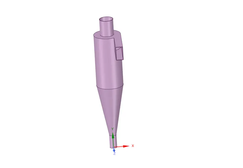
The geometry of the cyclone separator considered for this study is given below:
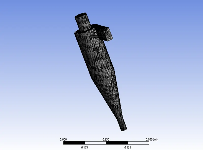
The mesh is shown below:
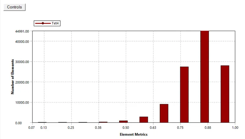
The mesh metric is shown below for the above mesh :
RESULTS AND ANALYSIS
An analysis of the cyclone separator model is carried out by varying the particle diameter from 1 to 5`\mum` in steps of 1 `\mu m` and calculate the separation efficiency in each case. The inlet velocity is kept as 3m/s.
Another set of analysis is carried out by varying the inlet velocity from 1 to 5 m/s in steps of 1 m/s and calculate the separation efficiency and pressure drop in each case.
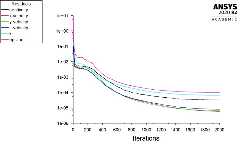
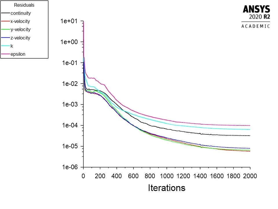
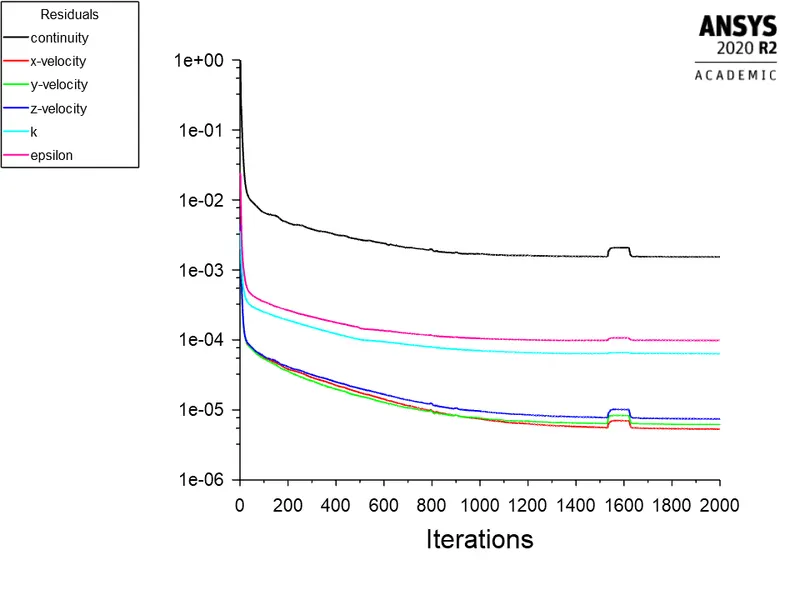
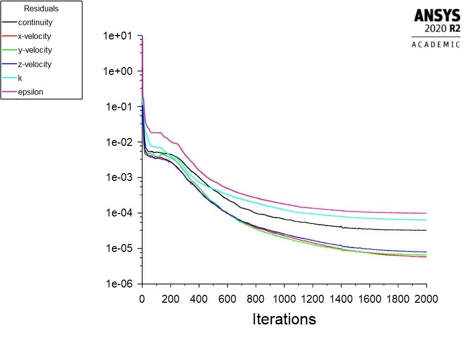
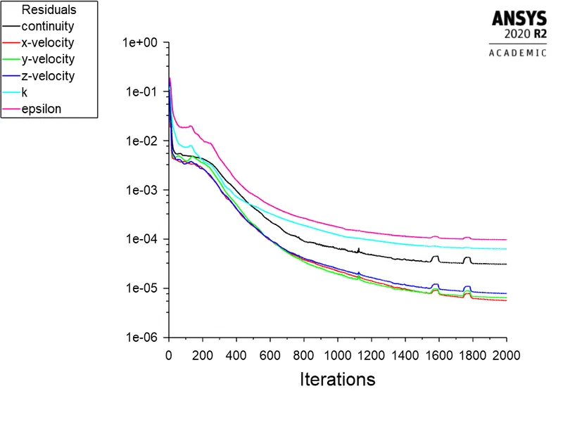
Simulations are run till convergence for all the cases for different particle size. The residual plots indicating the convergence is shown below for all the run cases.
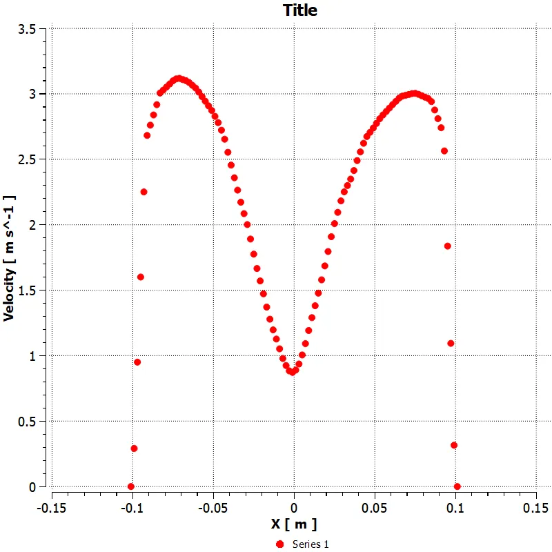
The velocity distribution for an inlet velocity of 3 m/s for a cyclone. The velocity at the midplane of the cyclone at a height of 0.55 m from the base is as shown below:
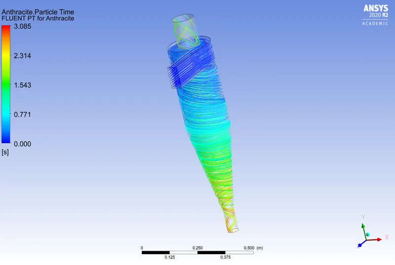
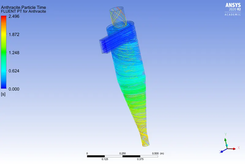
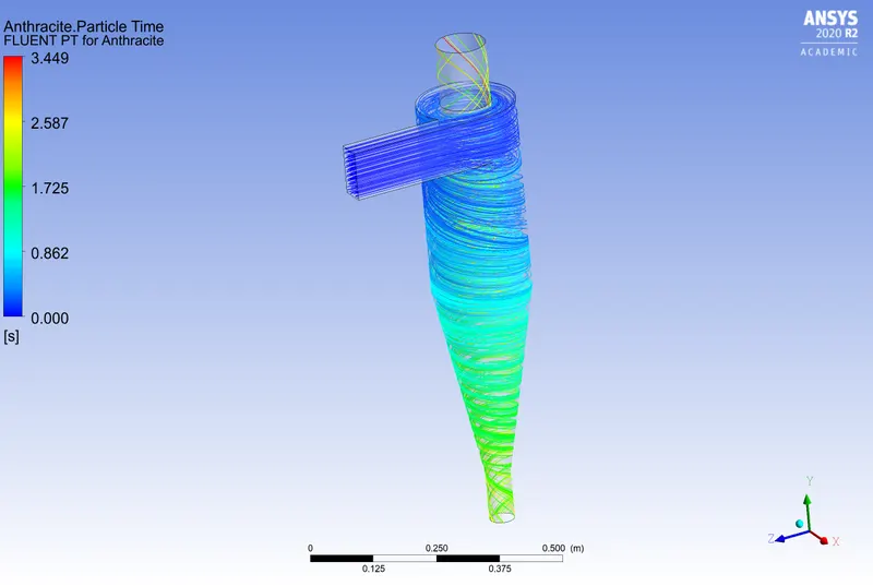
The particle track image for the different size of the particle is shown below:
The image for `1 \mu m` is given below:
The image for `2 \mu m` is given below:
The image for `3 \mu m` is given below:
The image for `4 \mu m` is given below:
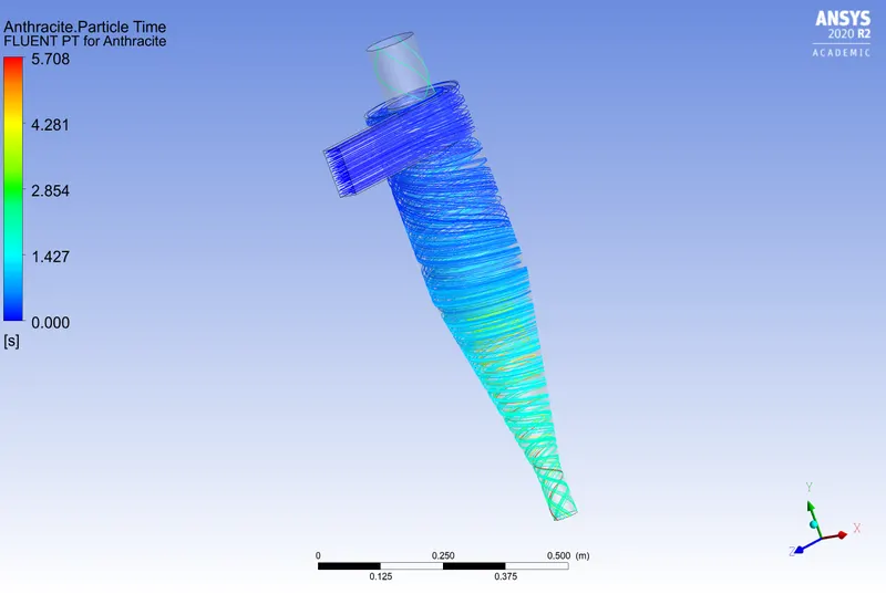
The image for `5\mu m` is given below:
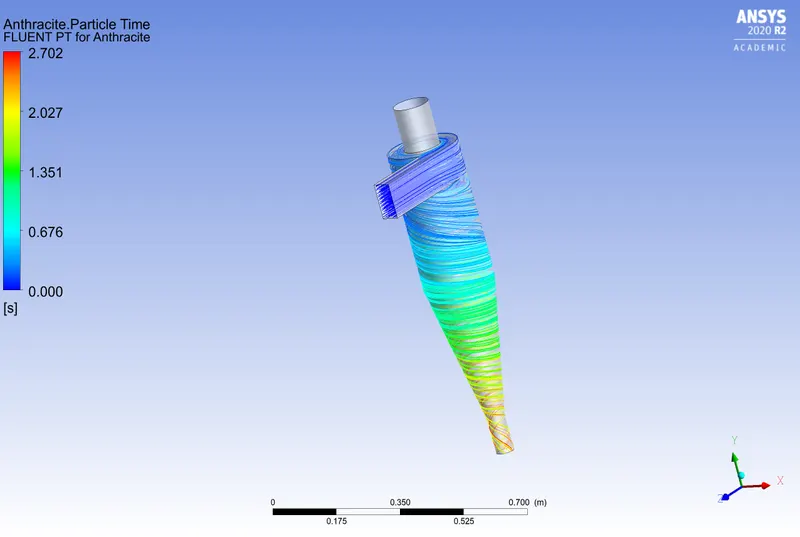
The number of particles tracked depends on the mesh resolution. In this current mesh, 124 particles are tracked. The efficiency can be calculated using the formula efficiency `\eta =` Trapped particles/Number of particles.
The results of the above simulation are tabulated in the tables shown below:
| Particle size | 1`\mu m` | 2`\mu m` | 3`\mu m` | 4`\mu m` | 5`\mu m` |
| Numbers Tracked | 124 | 124 | 124 | 124 | 124 |
| Escaped | 22 | 20 | 16 | 4 | 0 |
| Trapped | 32 | 99 | 108 | 120 | 124 |
| Incomplete | 70 | 5 | 0 | 0 | 0 |
| Efficiency | 25.8% | 79.83% | 87.09% | 96.77% | 100% |
It can be seen that as the size of the particle increases the separation efficiency also increases. It is because as the size of the particle increases the particles become heavier and it is easy to settle down. From the particle track images, it can be seen that as the particle size increases the particle that flies out through the top outlet reduces. It can be inferred that as the size of the particle increases the heavier it becomes and tries to settle down rather than to fly off.
The study must be carried out for a finer mesh to understand the effects more clearly. It can be inferred that increasing the length of the top outlet can reduce the number of particles that escape through the top and thus increase the efficiency of the separator. Further studies need to be carried out to understand the effect of different parameters on the efficiency.
Another set of simulations are carried out by changing the inlet velocity for a particle size of 5 `\mu m`. The same geometry and mesh are used for the study. The velocity is varied between 1 m/s to 5 m/s with a step size of 1 m/s. The findings from the study are tabulated below:
| Inlet Velocity | 1 m/s | 2m/s | 3 m/s | 4 m/s | 5 m/s |
| Tracked Particles | 124 | 124 | 124 | 124 | 124 |
| Escaped | 18 | 6 | 0 | 0 | 0 |
| Trapped | 106 | 118 | 124 | 124 | 124 |
| Incomplete | 0 | 0 | 0 | 0 | 0 |
| Efficiency | 85.4% | 95.16% | 100% | 100% | 100% |
| Inlet Pressure | 1.8059Pa | 7.86205Pa | 18.2947Pa | 33.1137Pa | 52.3087Pa |
| The pressure at lower outlet | 0 | 0 | 0 | 0 | 0 |
| The pressure at the upper outlet | 0 | 0 | 0 | 0 | 0 |
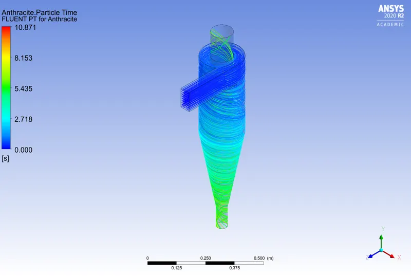
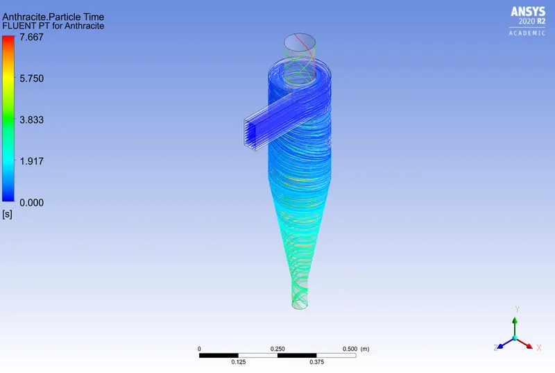
The particle track plot in the cyclone for different velocities is as shown below:
For inlet velocity = 1 m/s.
For inlet velocity = 2 m/s.
For inlet velocity = 3 m/s.
For inlet velocity = 4 m/s.
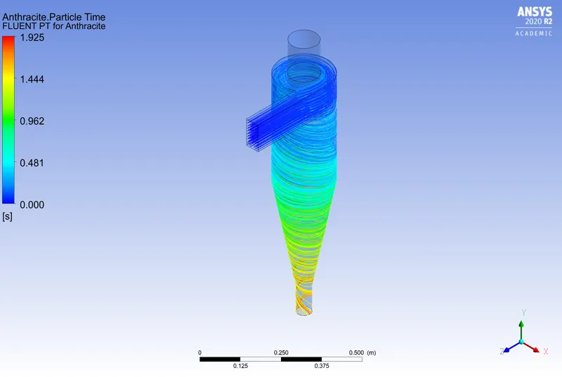
For inlet velocity = 5 m/s.
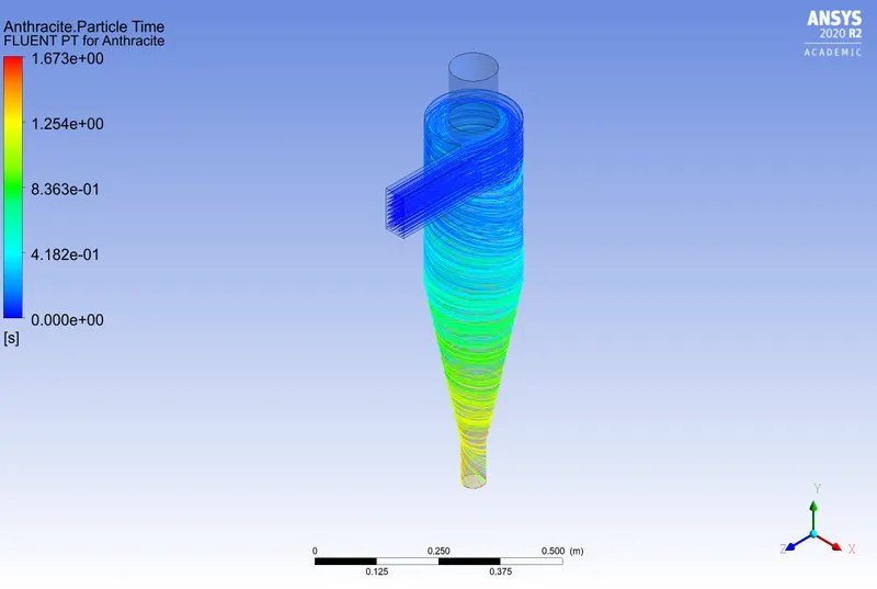
It can be seen that as the inlet velocity is increased, the maximum residence time of the particle can be reduced. The results of the study are
| Inlet velocity | 1 m/s | 2 m/s | 3 m/s | 4 m/s | 5 m/s |
| Residence time | 10.871 s | 7.667 s | 2.702 s | 1.925 s | 1.673 s |
As the inlet velocity increases it can be seen that the residence time of the particle decreases, this is because the particle can move much faster to settle down.
CONCLUSION
From the above study, it can be concluded that as the particle size increases, i.e when the particle size is greater than 2 `\mu m`the efficiency is increased. Or we can say that the cyclones are efficient for relatively large-sized particles.
It is also interesting to note that, as the inlet velocity increases the residence time of the particle decreases. That is the particulate matter settles faster as the inlet velocity is higher.
It is also seen that as the inlet velocity increases the pressure at the inlet becomes higher and therefore the pressure drop is higher as the inlet velocity is higher. As the inlet velocity increases the energy expended also increases.