Cyclone Separator Challenge
Aim: To perform steady-state analysis on Cyclone Separator using DPM(Discrete Phase model).
Introduction and Theory:
Cyclonic separation is a method of removing particulates from an air, gas, or liquid stream, without the use of filters, through vortex separation. When removing particulate matter from liquid, a hydrocyclone is used; while from gas, a gas cyclone is used. Rotational effects and gravity are used to separate mixtures of solids and fluids. The method can also be used to separate fine droplets of liquid from a gaseous stream.
A high speed rotating airflow is established within a cylindrical or conical container called a cyclone. Air flows in a helical pattern, beginning at the top (wide end) of the cyclone and ending at the bottom (narrow) end before exiting the cyclone in a straight stream through the center of the cyclone and out the top. Larger (denser) particles in the rotating stream have too much inertia to follow the tight curve of the stream, and thus strike the outside wall, then fall to the bottom of the cyclone where they can be removed. In a conical system, as the rotating flow moves towards the narrow end of the cyclone, the rotational radius of the stream is reduced, thus separating smaller and smaller particles. The cyclone geometry, together with the volumetric flow rate, defines the cut point of the cyclone. This is the size of the particle that will be removed from the stream with a 50% efficiency. Particles larger than the cut point will be removed with greater efficiency and smaller particles with a lower efficiency as they separate with more difficulty or can be subject to re-entrainment when the air vortex reverses direction to move in direction of the outlet.
Applications: Sawmills, Oil refining, Vacuum cleaners.
Models used to determine cyclone efficiency:
1. Iozia and Leith model
Iozia and Leith (1990) logistic model is a modified version of Barth (1956) model which is developed based on force balance. The model assumes that a particle carried by the vortex endures the influence of two forces: centrifugal force and flow resistance.
The collection efficiency `η_i`of particle diameter `d_(PI)`can be calculated from;
`η_i = 1 /(1+(d_ (pc)/d_(PI))^β`
Slope parameter expression is derived based on the statistical analysis of experimental data of cyclone with D = 0.25 m.
`d_(PI)`= Particle diameter
`d_(pc)` is the 50% cut size.
2. Li and Wang model
The Li and Wang model(1989) includes particle bounce or re-entrainment and turbulent diffusion at the cyclone wall. A two-dimensional analytical expression of particle distribution in the cyclone is obtained.
`η_i``η_i = 1-exp(-lambda*theta1)`
where,
`η_i`= Collection efficiency for a particle of any size
3. Koch and Licht model
Koch and Licht(1977) collection theory recognized the inherently turbulent nature of cyclones and the distribution of gas residence times within the cyclone. Koch and Licht describe particle motion in the entry and collection regions with the additional following assumptions:
- The tangential velocity of a particle is equal to the tangential velocity of the gas flow, i.e. there is no slip in the tangential direction between the particle and the gas.
- The tangential velocity is related to the radius of cyclone `uR^n` = constant.
`eta_i = 1- exp{-2*[(G*tau_i*Q*(n+1))/D^3]^(0.5/(n+1))}`
4. Lapple model
Lapple(1951) model was developed based on force balance without considering the flow resistance. Lapple assumed that a particle entering the cyclone is evenly distributed across the inlet opening. The particle that travels from inlet half-width to the wall in the cyclone is collected with 50% efficiency.
The efficiency of collection of any size of a particle is given by
`η_i = 1 /(1+(d_ (pc)/d_(PI))^2`
Modeling Approach:
Pre-Processing:
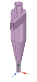
Step 1: Importing cyclone separator geometry into SpaceClaim
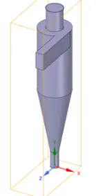
Extracting fluid volume for analysis:
Step 2: Meshing
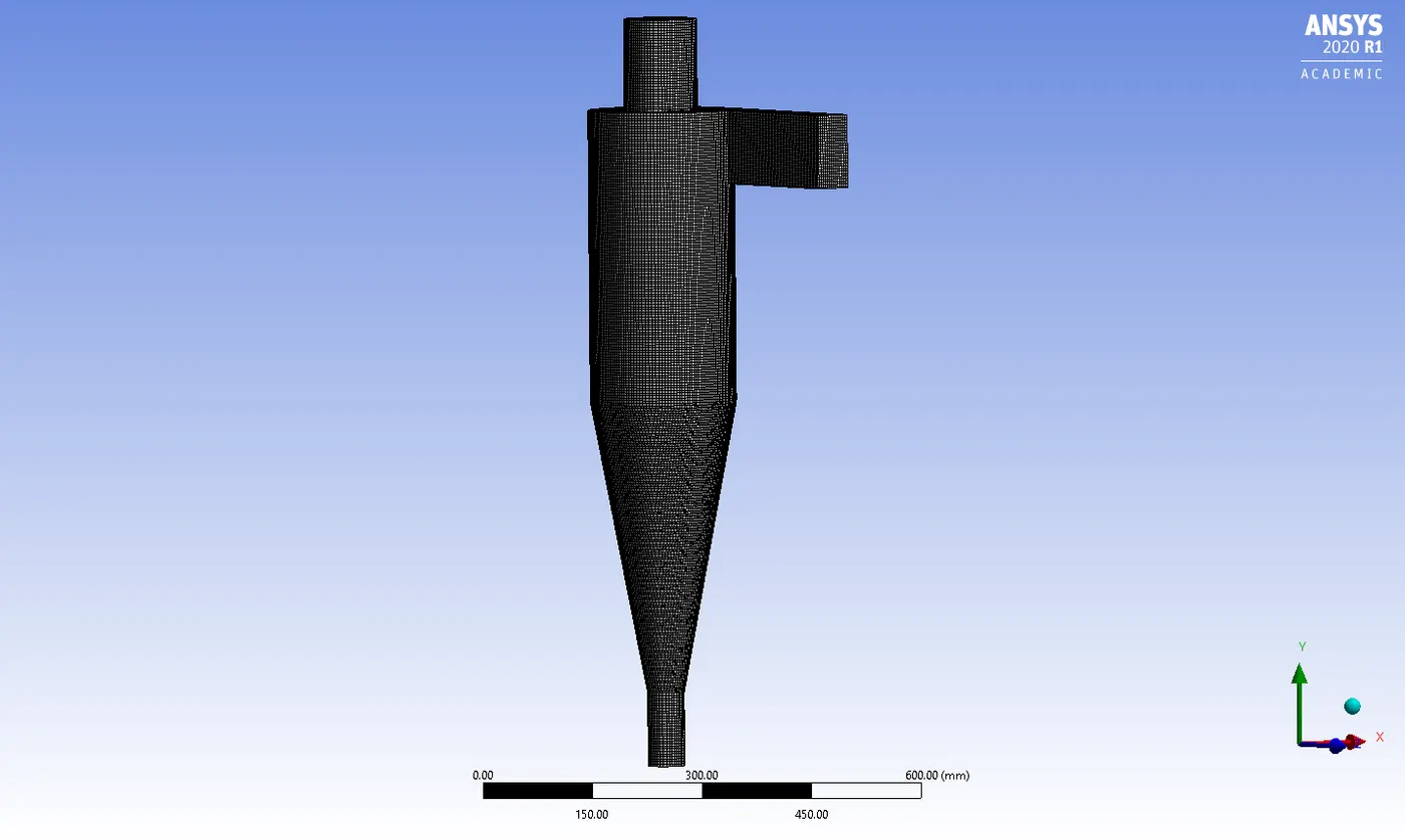
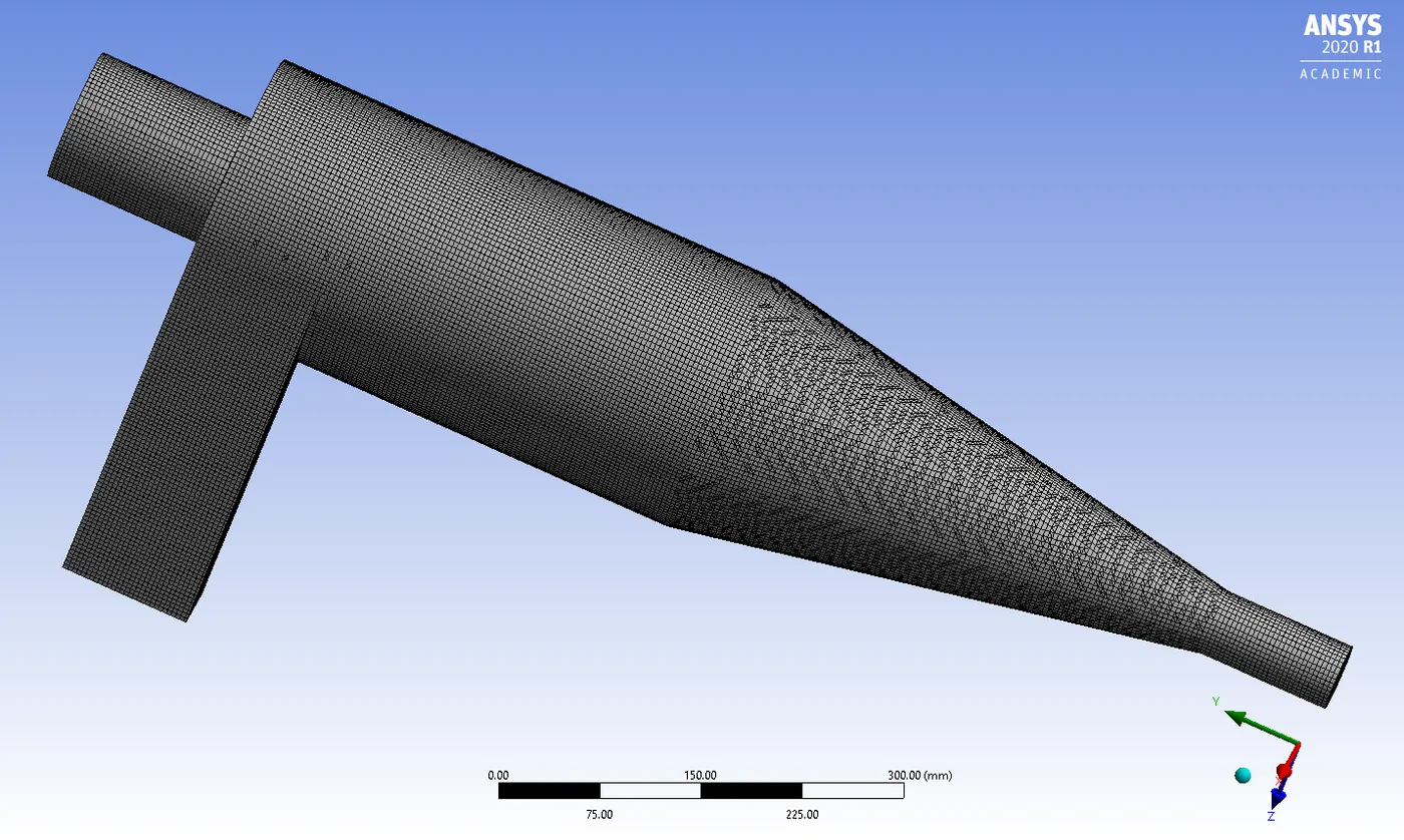
A Cut-cell Assembly meshing was employed to create a structured mesh with a body sizing of 5mm.
Statistics of mesh:

The mesh created is depicted below:
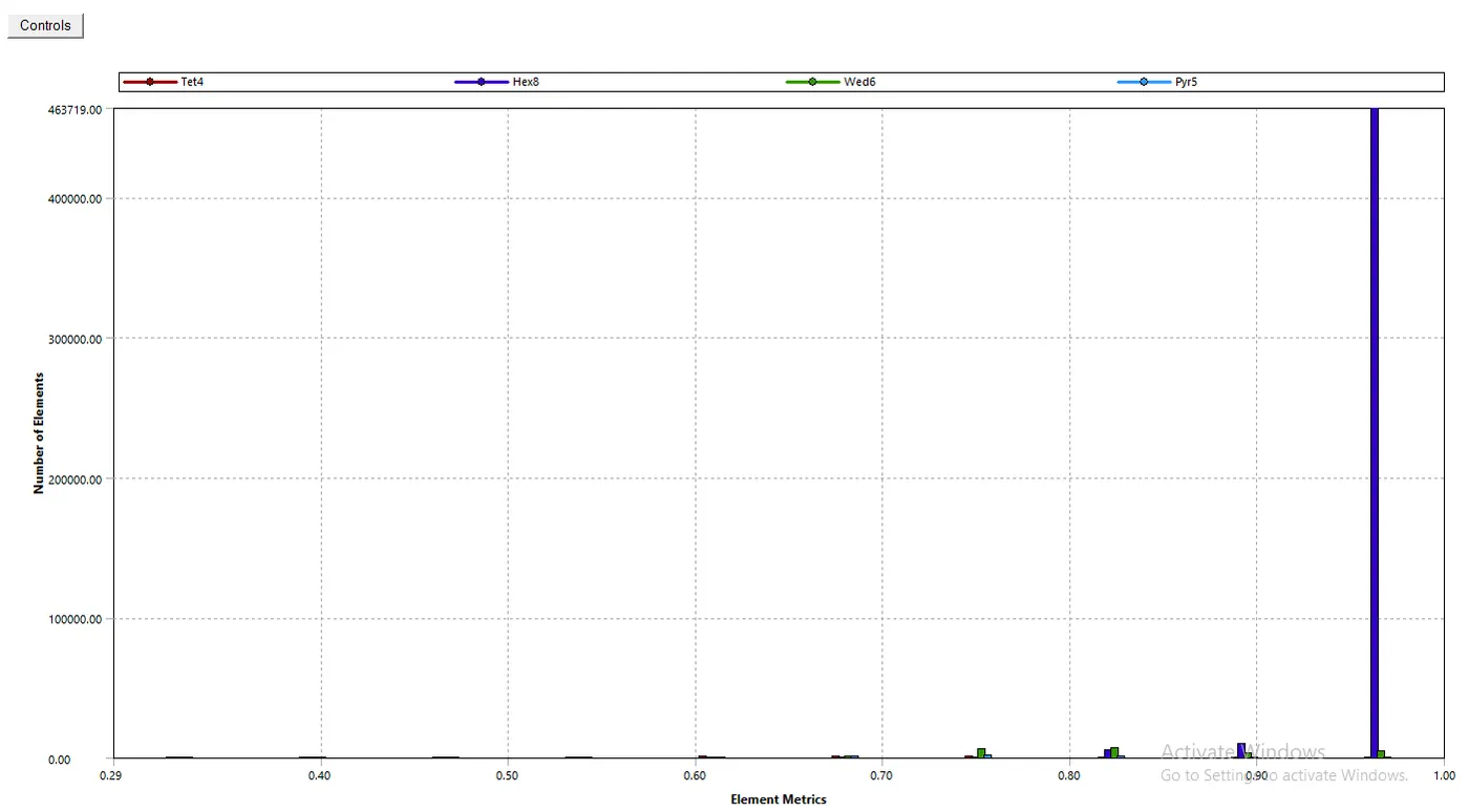
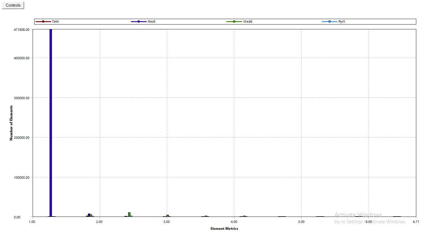
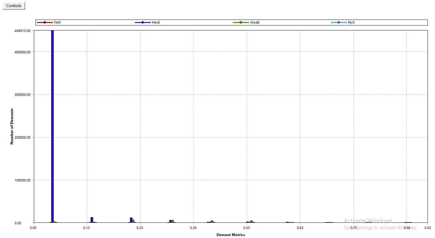
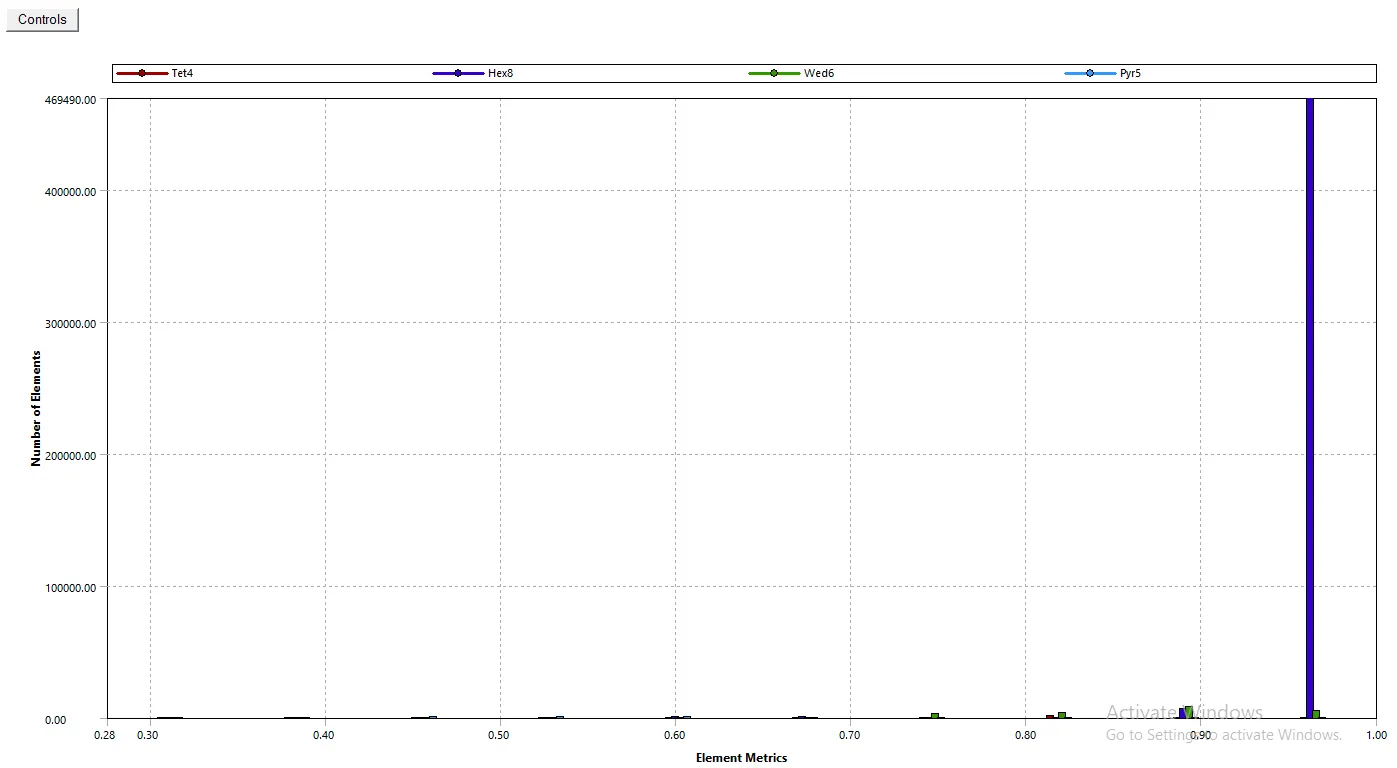
Mesh Quality:
1. Element Quality

2. Aspect Ratio

3. Skewness

4. Orthogonal Quality

Step 3: Solving using Fluent:
Pressure-based solver with absolute velocity formulation, and steady-state.
Gravity enabled with value 9.81 `m/s^2`
Viscous model:
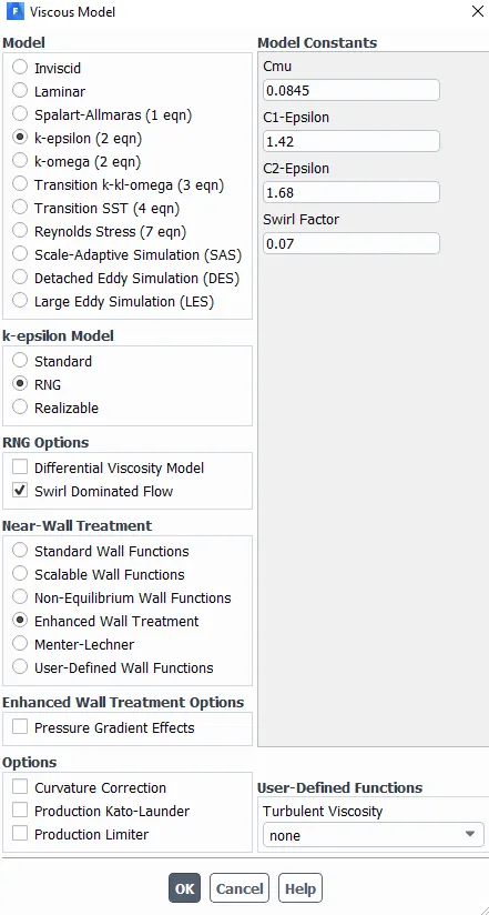
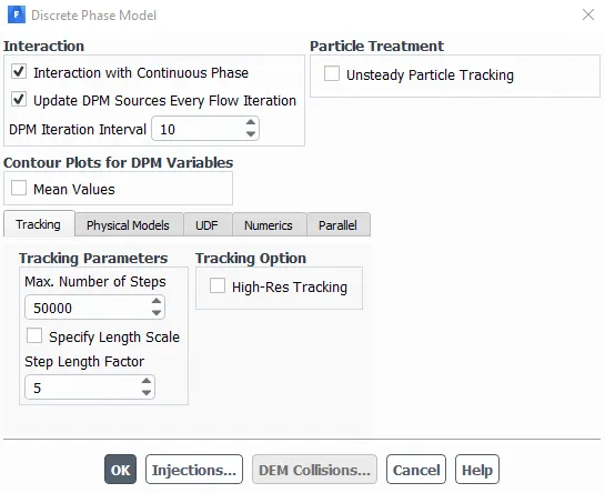
DPM properties:
Injection properties:
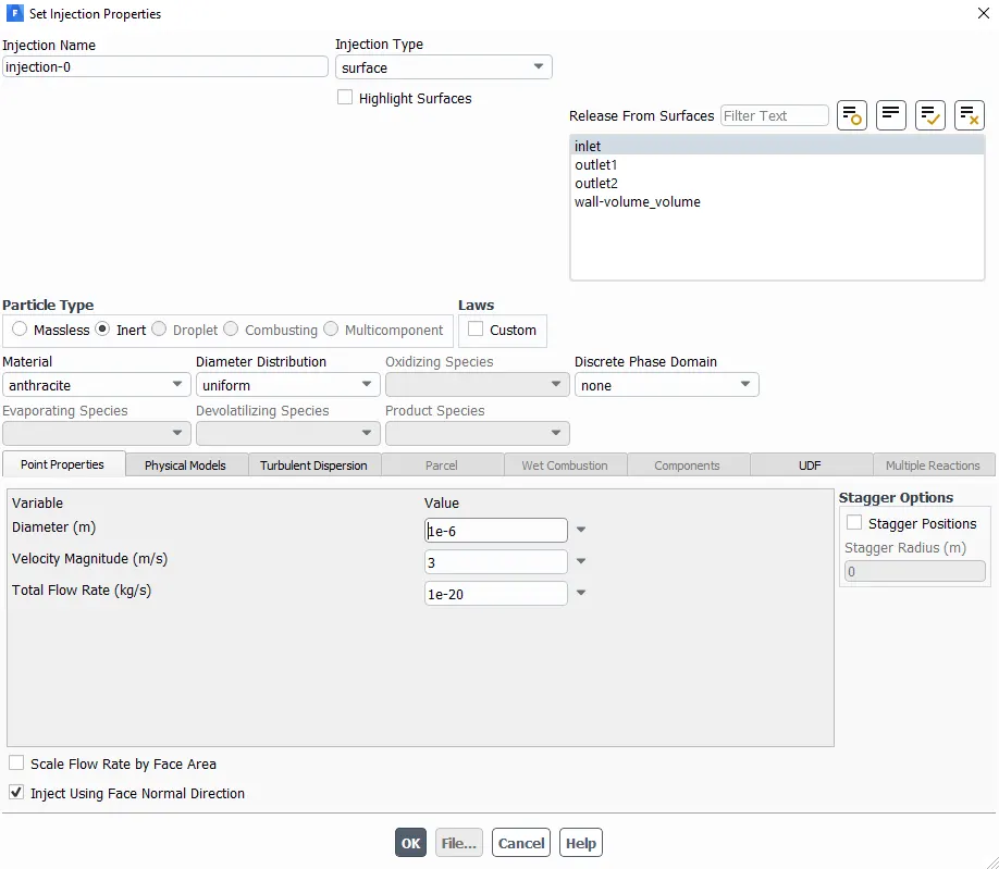
The diameter and velocity of particles were changed according to analysis requirements.
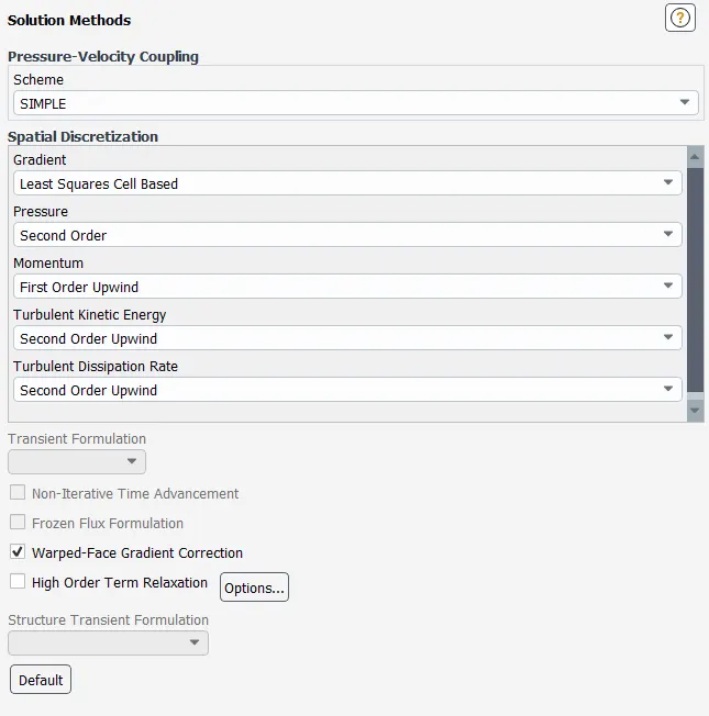
Solution Method:
For this particular simulation, we will be varying particle diameter and flow speed to get useful characteristics such as separation efficiency and pressure drop across the separator.
Case I: Varying Particle diameter
1.1. Particle diameter= 1 `mum`, flow speed= 3m/s
1.2. Particle diameter= 3 `mum`, flow speed= 3m/s
1.3. Particle diameter= 5 `mum`, flow speed= 3m/s
Case II: Varying flow speed
2.1. Particle diameter= 5 `mum`, flow speed= 1m/s
2.2. Particle diameter= 5 `mum`, flow speed= 4m/s
2.3. Particle diameter= 5 `mum`, flow speed= 5m/s
Residuals:
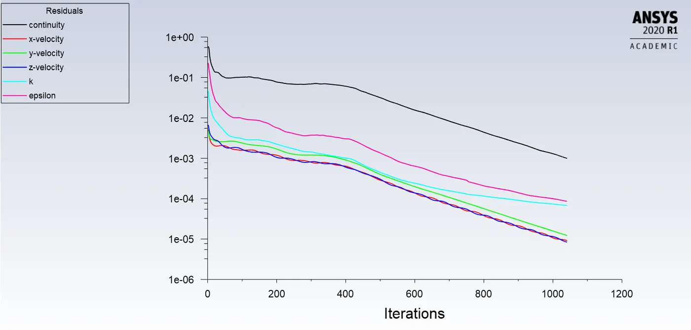
Case 1.1.
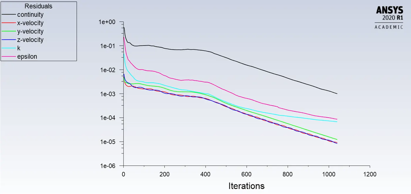
Case 1.2.
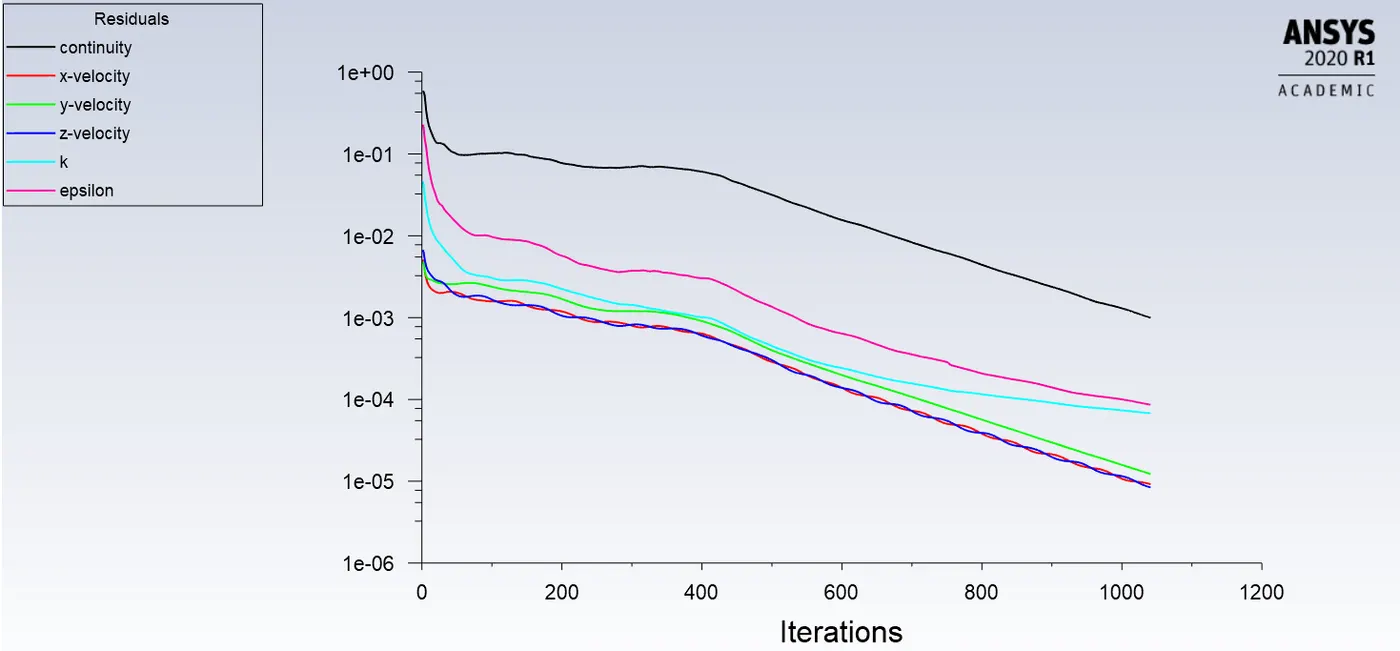
Case 1.3.
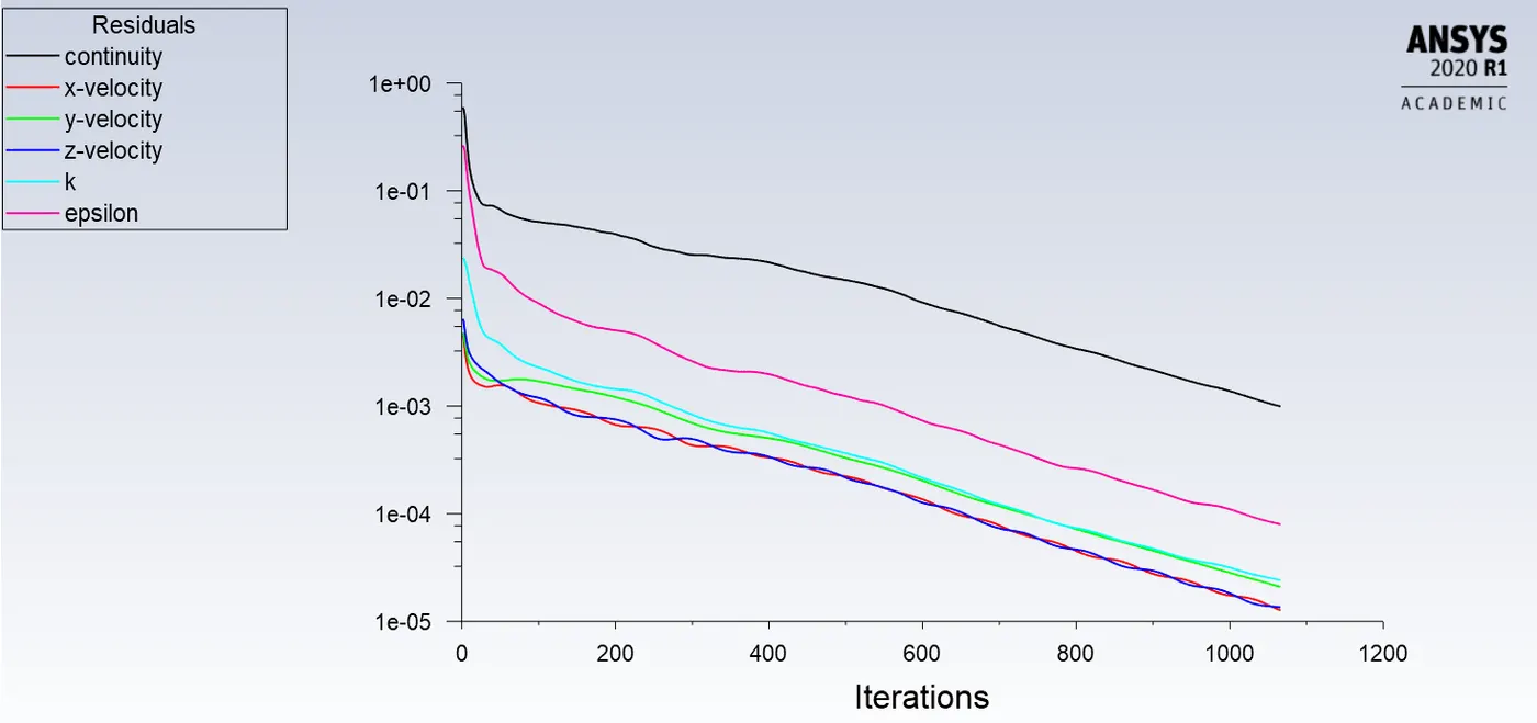
Case 2.1.
Case 2.2.
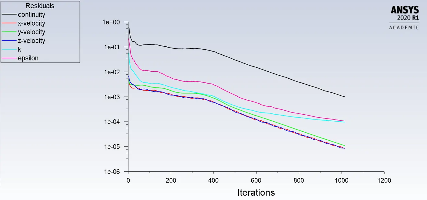
Case 2.3.
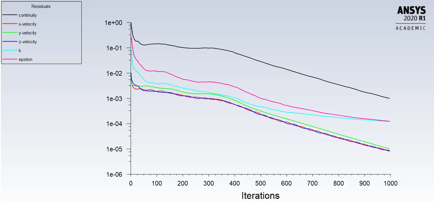
The residuals are dying down hence we can say that the solution is converged.
Results:
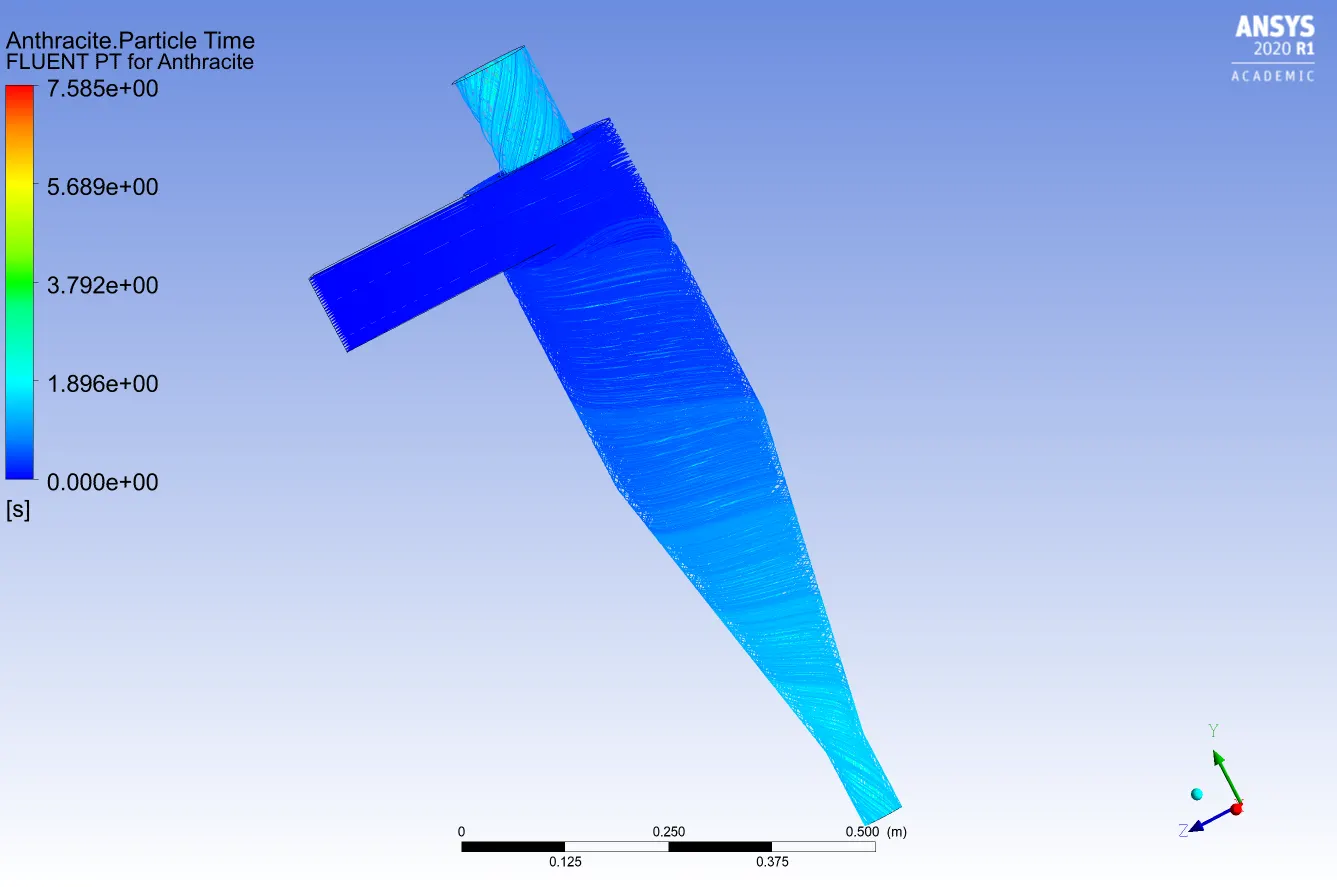
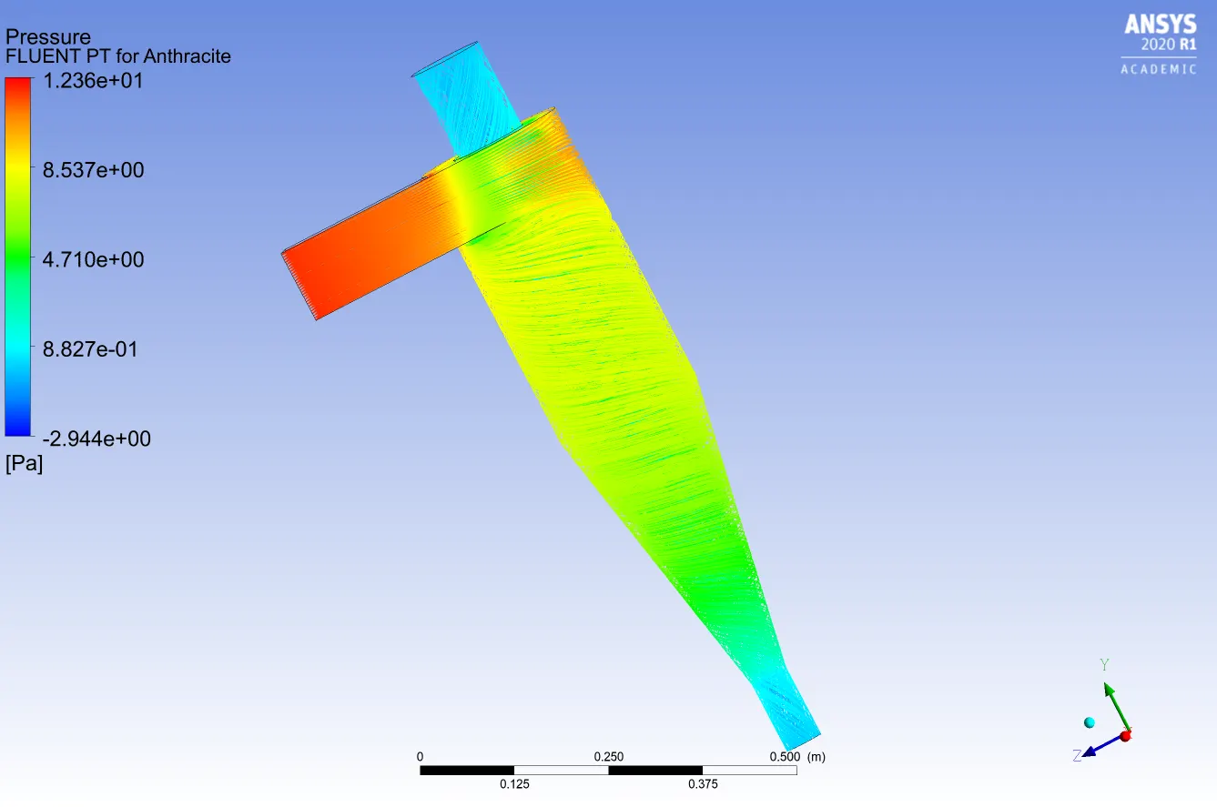
Case 1.1.
Anthracite Particle residence time:
Pressure contour:
Separation Efficiency = Trapped particles/No. of particles tracked.

Separation Efficiency = 216/435 = 49.65%
Pressure drop = Inlet Pressure - Outlet Pressure
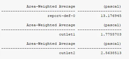
Note: Pressure values are gauge pressure
Pressure drop = Inlet Pressure - Outlet Pressure(top outlet/outlet 1) = 11.401 Pa
Case 1.2.
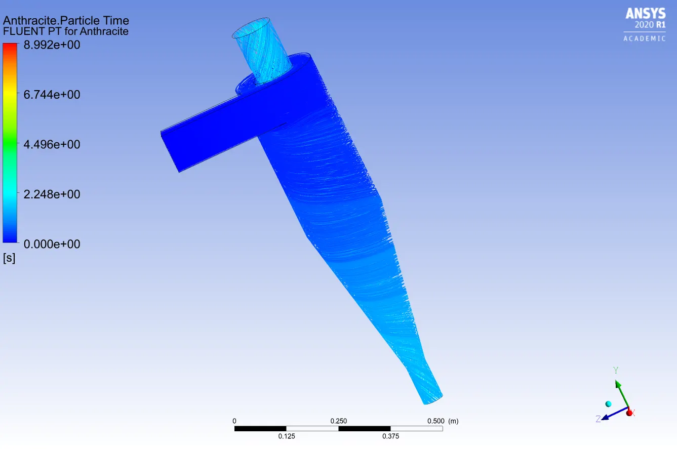
Anthracite Particle residence time:
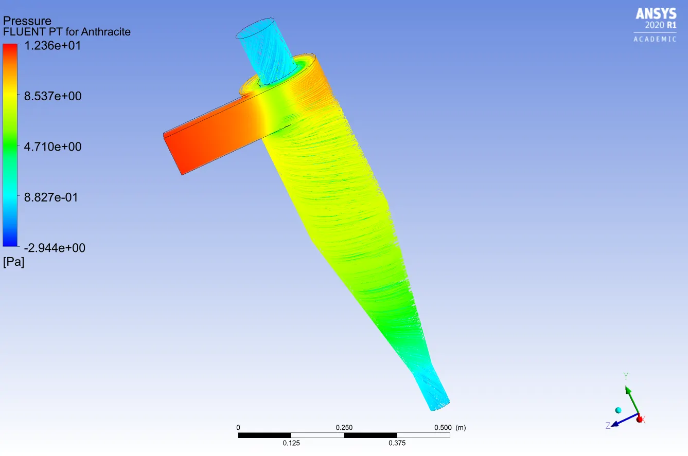
Pressure contour:
Separation Efficiency = Trapped particles/No. of particles tracked.

Separation Efficiency = 241/435 = 55.4%
Pressure drop = Inlet Pressure - Outlet Pressure
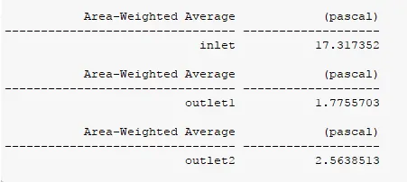
Note: Pressure values are gauge pressure
Pressure drop = Inlet Pressure - Outlet Pressure(top outlet/outlet 1) = 15.54 Pa
Case 1.3.
Anthracite Particle residence time:
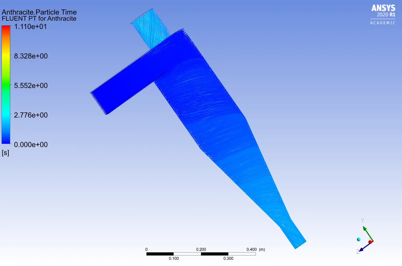
Pressure contour:
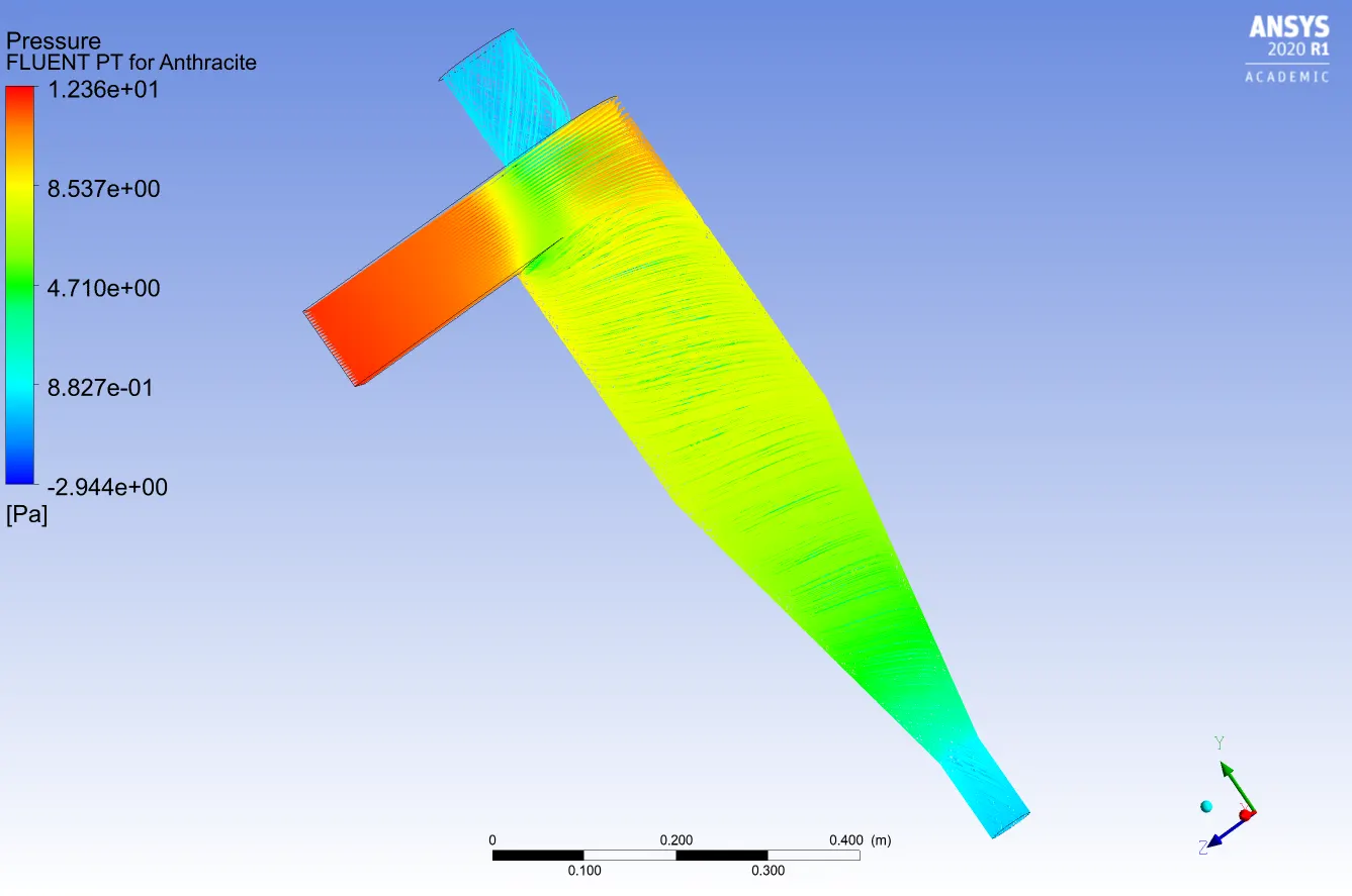
Separation Efficiency = Trapped particles/No. of particles tracked.

Separation Efficiency = 299/435 = 68.73%
Pressure drop = Inlet Pressure - Outlet Pressure
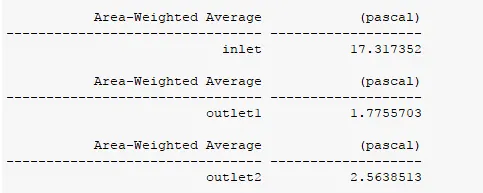
Note: Pressure values are gauge pressure
Pressure drop = Inlet Pressure - Outlet Pressure(top outlet/outlet 1) =15.54 Pa
Case 2.1.
Anthracite Particle residence time:
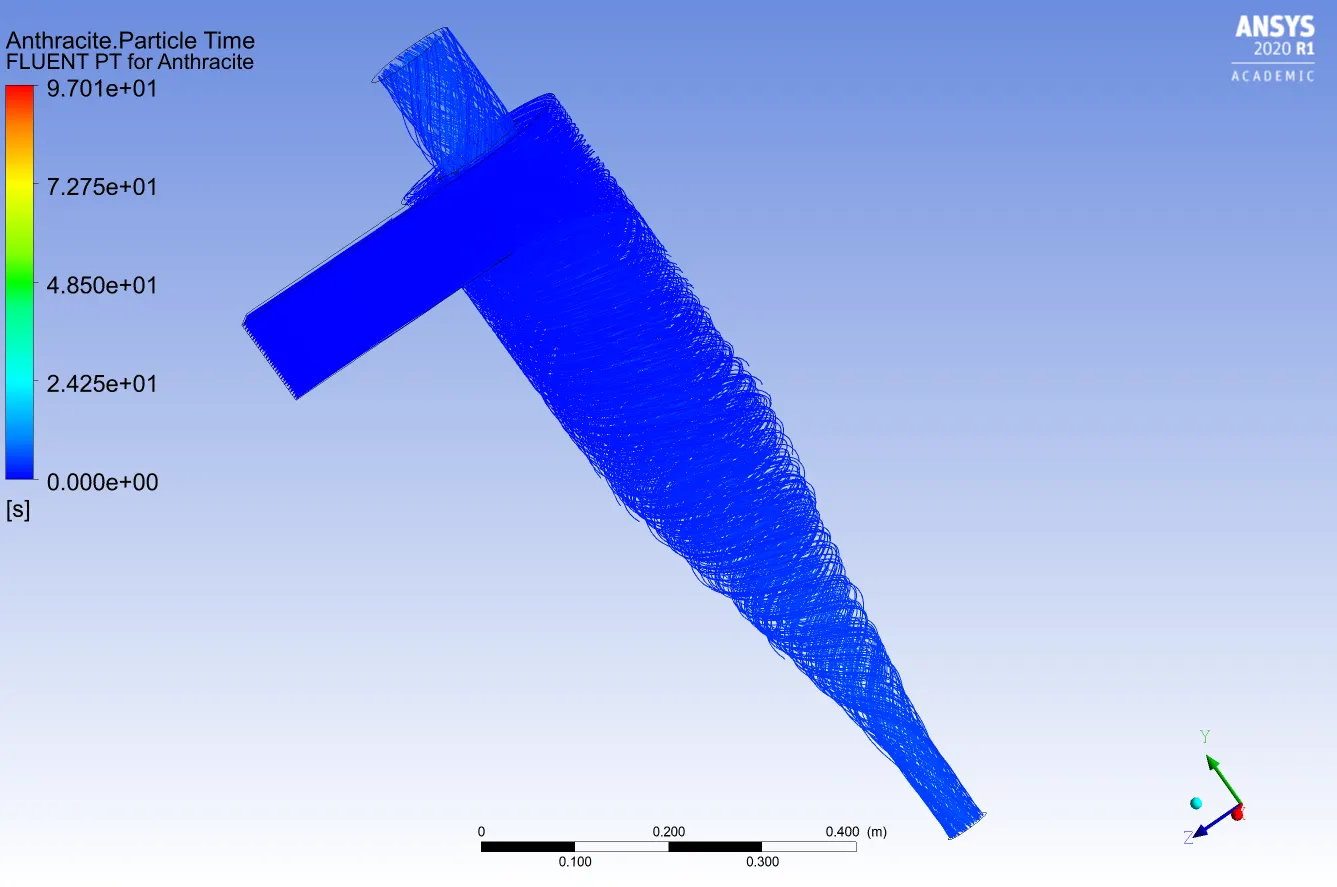
Pressure contour:
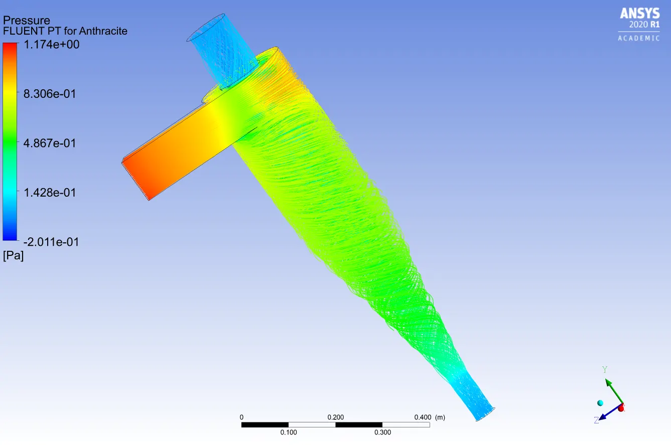
Separation Efficiency = Trapped particles/No. of particles tracked.

Separation Efficiency = 133/435 = 30.57%
Pressure drop = Inlet Pressure - Outlet Pressure
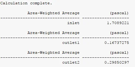
Note: Pressure values are gauge pressure
Pressure drop = Inlet Pressure - Outlet Pressure(top outlet/outlet 1) = 1.54 Pa
Case 2.2.
Anthracite Particle residence time:
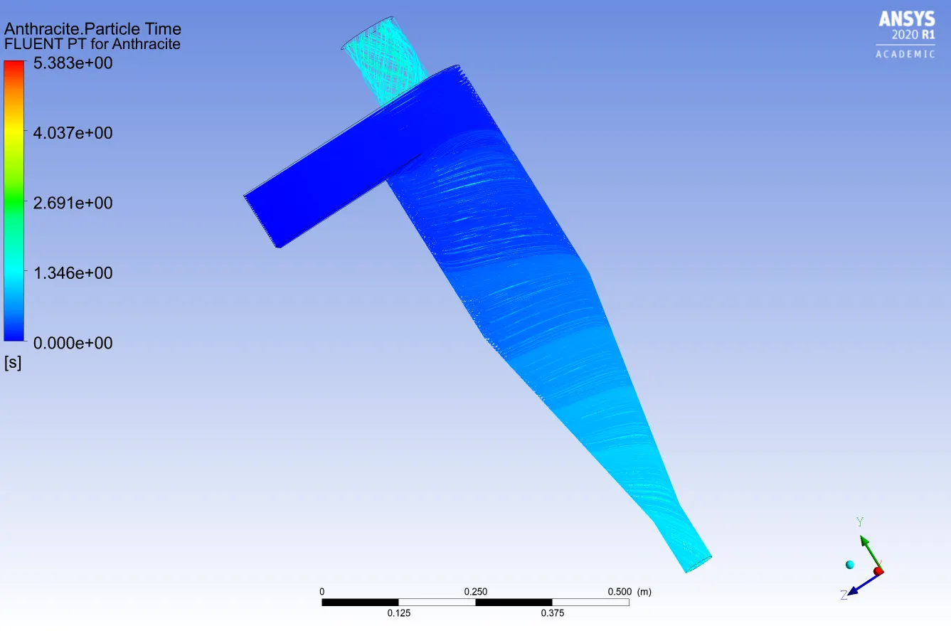
Pressure contour:
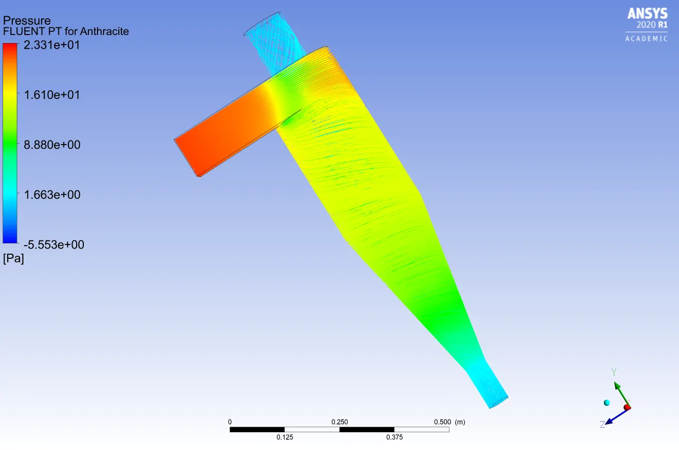
Separation Efficiency = Trapped particles/No. of particles tracked.

Separation Efficiency = 334/435 = 76.78%
Pressure drop = Inlet Pressure - Outlet Pressure
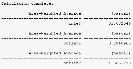
Note: Pressure values are gauge pressure
Pressure drop = Inlet Pressure - Outlet Pressure(top outlet/outlet 1) = 28.398 Pa
Case 2.3.
Anthracite Particle residence time:
Pressure contour:
Separation Efficiency = Trapped particles/No. of particles tracked.
Separation Efficiency = 334/435 = 76.78%
Pressure drop = Inlet Pressure - Outlet Pressure
Note: Pressure values are gauge pressure
Pressure drop = Inlet Pressure - Outlet Pressure(top outlet/outlet 1) = 28.398 Pa
Conclusion:
1. Separation Efficiency depends on both the particle diameter and velocity of the particles. Increasing both the parameters increases separation efficiency.
2. Increasing velocity has a greater impact on separation efficiency than particle diameter.
3. Pressure drop is almost constant with increasing particle diameter but increases rapidly with increasing velocity.
4. Outlet 1(top) has less pressure than Outlet 2(bottom) because clean air with fewer particulates is sucked out through the top which has to be at lower pressure for the air to flow.