Cyclone Separator Challenge
#AIM:
* At a velocity of 3 m/s for both fluid and particle vary the particle diameter from 1 `mu m` to 5 `mum` and calculate the efficiency in each case.
* To vary the fluid and particle velocity from 1 m/s to 5 m/s for a particle diameters of 5 `mum` and calculate efficiency and pressure drop in each case.
* To briefly explain different models used to measure the cyclone efficiency.
#INTRODUCTION:
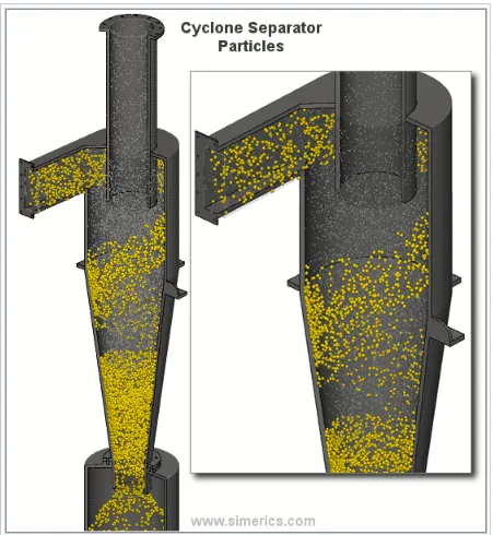
Cyclonic separation is a method of separating the solid particles from liquid, air, gas stream through vortex without using any filters. Separation of solid particles from liquid is carried out using hydrocyclone. Cyclone separators are also called as cyclones. Generally they have one inlet through which the contaminated fluid enters the cyclone chamber, contaminated fluid in the sense fluid with solid particle and it has 2 outlets, 1 outlet of collecting the solid particles which is usually present in the bottom of the cyclone separator and the other one at the top of the cyclone separator through which the cleaned fluid exits. The geometry of cyclone separator is such that it has a wide section in the top portion which becomes narrow as we move down.
The fluid which is contaminated with solid particle is called the continuous phase and the solid particles which is spread on the fluid is called discrete phase. As the fluid moves through the cyclone separator the swirling motion of fluid makes the denser solid particle difficult to stick with the fluid phase also because that these solid particles hits the walls of the cyclone separator it looses its momentum and hence falls into the outlet at the bottom from where it is being collected.
A general illustration of a cyclone separator is shown below,
Most of the cyclone separators are very much effective in removing particulate matters which are of size more than 10 `mum`. But there are certain high eficiency cyclone separators which are capable of removing particle of size between 2-5 `mum`. But generally a cyclone separator is said to be efficient in removing particles which are of size more than 10 `mum`. For paticles of size more than 200 `mum` cyclonic separation is not a good to go option in such cases gravity settling chambers and momentum separators are good options.
A cyclone separator is generally able to remove 50-99% of the solid particles in the contaminated fluid. This efficiency mainly depends on size of the particulate matter, smaller the particulate matter it is difficult to remove the particles. There are several advantages of using a cyclone separator, first thing it is easy to install also there is no need for any maintainence since a cyclone separator does not have any moving parts. It collects the solid particles dry hence it becomes easy removal of solid particles from the cyclone separator. As there are these advantages cyclone separator also have certain disadvantages. First thing standard cyclones are not able to handle fine particles, second cyclone separators cannot handle sticky particles.
Cyclone performance is usually described using cut diameter, collection efficiency and pressure drop.
* Cut diameter: It is defined as the size of particles collected with 50% collection efficiency. It indicates the size range of particels that a cyclone separator can collect. The cut diameter is usually expressed using the formula as given below.
`d_(pc) = ((9*mu*B_(c))/(2*pi*N*v_(i)*(rho_(p)-rho)))^(1/2)`
where `mu -` viscosity (Pa*s).
`B_(c) -` Inlet width (m).
`N -` effective number of turns (5-10 for common cyclone)
`v_(i) -` inlet gas velocity (m/s).
`rho_(p) -` particle density (Kg/m^3).
`rho -` gas density (Kg/m^3).
* Cyclone efficiency: There are different empirical models that are developed to define the cyclone efficiency. Cyclone efficiency in general is defined as ratio of particle of a particular size that is being trapped or collected by the cyclone separator to that of same size particle entering into the cyclone. Below are some of the models that are used to measure cyclone efficiency.
1. Iozia and Leith model:
This model is developed based on the force balance. The model assumes that since the particle are carried by the vortex, it is mainly influenced by 2 forces namely the centrifugal force Z and a flow resistance W. The collection efficiency `eta_(i)` of particle diameter `d_(p)` can be calculated from
`eta_(i) = 1/(1+(d_(pc)/d_(p))^beta`
where `d_(pc) -` Cut diameter at 50% efficiency (m). (given by barth)
`d_(p) -` Particle diameter (m).
`beta`is an expression for slope parameter derived based on the statistical analysis of experimental data of a cyclone with D = 0.25 m which is given as
`beta = 0.62-0.87-log(d_(pc)/100)+5.21*log((a*b)/D^2)+1.05*[log((a*b)/D^2)]^2`
where, a - Cyclone inlet height (m).
b - Cyclone inlet width (m).
`d_(pc) =[(9*mu*Q)/(pi*rho_(p)*z_(c)*v_(tmax)^2)]`
where `Z_(c)` is core length and `d_(c)` is core diameter are given as,
`Z_(c) = (H-S)-[(H-S)/((D/B)-1)]*[((9*d_c)/B)-1]`, for `d_(c) > B`
where `B -`Cyclone dust outlet diameter(m).
`H -`Cyclone height (m).
`S -` Cyclone gas outlet duct length (m).
`D -` Cyclone body diameter (m).
`Z_c = H-S`, for `d_c < B`
`d_c = 0.47*D*((a*b)/D^2)^-0.25*(D_(e)/D)^1.4`
where `D_e -`Cyclone gas outlet diameter (m).
2. Li and Wang model:
This model considers turbulent diffusion and re-entertainment at cyclone wall. A two dimensional analytical equation is developed to express the distribution of particles inside the cyclone. The model is developed based on following assumptions:
* The radial particle velocity and radial concentration is not constant for uncollected particles within the cyclone.
* Boundary conditions with the consideration of turbulent diffusion coefficient and particle bounce re-entertainment on the cyclone wall are:
`C = C_0` at `theta = 0`
`D_r*(delc)/(delr) = (1-alpha)*w*c` at r =D/2
where `C_0 -` Particle inlet concentration (Kg/m^3)
`D_r -` Radial turbulent diffusion coefficient.
`w -` Radial particle velocity (rad/s).
`alpha -` Particle bounce or re-entertainment coefficient.
* The tangential velocity is related to the radius of the cyclone by `u*R^n = constant`
The concentration distribution in a cyclone is given as:
`C(r,theta) =( c_0*(r_w-r_n)*exp{-lamda*[1/(k*(1+n))*r^(1+n)]})/(int_(r_(n))^(r_(w))exp{(1/(K*(1+n)))*r^(1+n)}*dr`
where `n -` Cyclone vortex exponent (0.5 < n<1).
`K -`Cyclone configuration and operating condition constant.
`lamda -`Characteristic value
Where `K = ((1-n)*(rho_p-rho_g)*d^2*Q)/(18*mu*b(r_w^(1-n)-r_n^(1-n))`
`Q -`Volumetric gas flow rate (m^3/s).
`r_(w) and r_(n) -` Radial dimensions (m)
`r_w = D/2` , `r_n = D_e/2`
where `lamda = ((1-alpha)*K*w_(w))/(D_(r)*r_(w)^n`
`D_r -`Radial turbulent diffusion coefficient.
`w_w -`Radial particle velocity (rad/s).
The resultant expression of the collection efficiency for particle of any size is given as
`eta_(i) = 1-exp{-lamda*theta_(i)}`
where `theta_i = 2*pi*(S+L)/a`
S - Cyclone gas outlet duct length (m).
L - natural length (m).
3. Koch and Licht model:
This model recognized inherently turbulent nature of cyclones and the distribution of gas residence times within the cyclone. Following assumptions are made in the model
* The tangential velocity of a particle is equal to the tangential velocity of the gas flow, i.e there is no slip between the particles and gas in the tangential direction.
* The tangential velocity is related to the radius of the cyclone by: `u*R^n = Constant`
efficiency `eta_(i) = 1-exp{-2*[(G*tau_(i)*Q)/D^3*(n+1)]^(0.5/(n+1))}`
where `G =(8*K_c)/(K_a^2*K_b^2)`
`n = 1-{1-((12*D)^0.14)/2.5}*{(T+460)/(530)}^0.3`
where `tau_i = (rho_p*d_p^2)/(18*mu)`
G is a factor related to the configuration of the cyclone, n is related to the vortex and `tau` is the relaxation term.
4. Lapple model:
Lapple model was developed based on force balance without considering the flow resistance. Assumptions made to develop the model includes:
* Each particle entering the is evenly distributed across the inlet.
* The particle that travels from half width of inlet to the wall is collected with 50% efficiency.
The empirical relationship developed to calculate the cut diameter,
`d_(pc) = ((9*mu*B_(c))/(2*pi*N*v_(i)*(rho_(p)-rho)))^(1/2)`
`mu -` viscosity (Pa*s).
`B_(c) -` Inlet width (m).
`N -` effective number of turns (5-10 for common cyclone)
`v_(i) -` inlet gas velocity (m/s).
`rho_(p) -` particle density (Kg/m^3).
`rho -` gas density (Kg/m^3).
Efficiency of collection of any size of particle is given by
`eta_i = 1/(1+((d_(pc))/d_(p))^2)`
* Pressure drop:
Determining pressure drop across a cyclone separator is important because it affects the performance parameters of the cyclones. Pressure drop in a cyclone is mainly because of inlet and exit losses and friction and kinetic energy losses. Normally the most significant pressure drop occurs in the body due to swril and energy dissipation. Pressure drop in a cyclone can be empirically given as,
`DeltaP =(0.0027*q^2)/(k_c*D_c^2*B_c*(L_c/D_c)^(1/3)*(Z_c/D_c)^(1/3)`
Where `q -`Volumetric flow rate.
`B_c -` inlet width (m).
`H_c -`inlet height (m).
`D_c -` outlet diameter (m).
`Z_c -`Cone length (m).
`L_c -` Cylinder length (m).
`Kc -`a dimensionless factor of cyclone inlet vanes.
`K_c = 0.5`for cyclones without vanes.
`K_c = 1.0` for cycone vanes that do not expand the entering gas or touch the outer wall.
`K_c = 2.0` for cyclone vanes that expand the entering gas and touch the outer wall
# SIMULATIONS:
* Geometry:
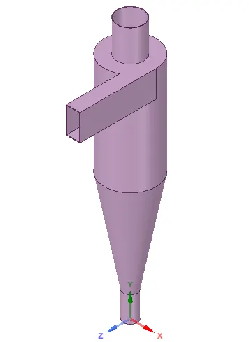
The cyclone separator geometry is opened in spaceclaim and the fluid volume is extracted using the prepare option. Three edges viz inlet and 2 outlet's are selected to extarct the fluid volume. Cyclone separator geometry used is as shown below,
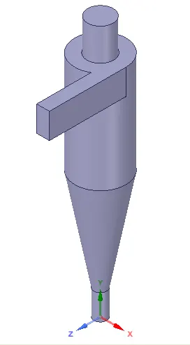
Fluid volume is extracted using the above geometry, extracted fluid volume is as shown below,
* Meshing:
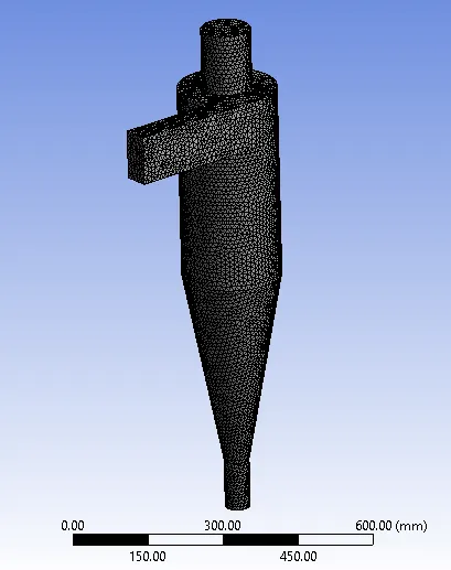
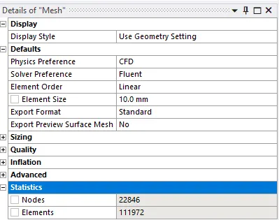
Extracted fluid volume is opened in the meshing module of the ansys workbench. Patches are inlet, outlet_1 for the top outlet through which the gas flows out, outlet_2 the bottom outlet through which the solid particles are collected. After providing names to the patches, mesh is applied on to the geometry. Normal tetrahedral meshes are applied. Cut cell method can be used to insert hexahedral meshes, but ansys R2 (academic) does not have cut cell feature hence Normal tetrahedral mesh is opted. Element size of 10 mm is provided for which total 111972 number of cells are generated. Meshed fluid volume looks as followw,
Below is the snip showing total number of cells,
Below is the mesh metrics of the mesh generated,
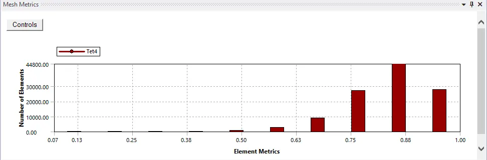
Element metrics is almost 13%, which is good enough to proceed further with the simulation.
* Solver setup:
teady state simulations are performed using a pressure based solver gravity is set to -9.81 m/s^2 in y-direction, since the fluid is predominantly flowing in y-direction. RNG K-ε viscous model with swirl dominated flow is used. Since the flow of fluid through the cyclone separator involves formation of swrils, the above mentioned viscous model can capture the results well.
As stated in the introductory part the fluid entering through the inlet will be contaminated with solid particles. The fluid is called the continuous phase and the solid particles are called the discrete phase. So in the fluent solver Discrete phase modelling is used so as to include the 2 phases. Under discrete phase model interaction with continuous phase option is selected and rest all parameters are left default.
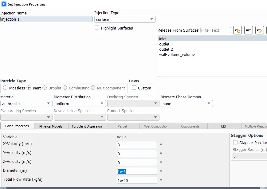
One of the important parameters that we have to define in discrete phase modelling is the injection modelling. Under injections options we can set the injection properties. Under injection properties we can set the solid particle material, type of injection viz surface injection, single injection etc. also we can set the velocity of solid particle entering through the inlet.
For this simulation Anthracite is used as solid particle and surface injection is used and inlet is used as the patch through which surface injection is taking place. X component of the Velocity is set for the solid particle. Injection can be saved using any suitable name. Particle type is selected as inert.
a snip of the injection parameter window is shown below,
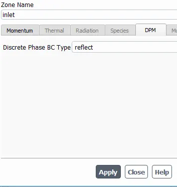
Boundary condition set of inlet as velocity inlet and here the fluid velocity is entered. In this simulation both fluid and particle velocity is considered same. Also the discrete pahse BC type of inlet is set as reflect. A snip of the DPM tab is given below,
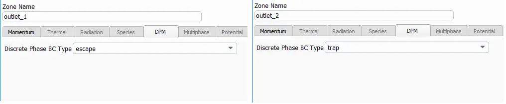
Outlet boundary's are set as pressure outlet and the discrete phase BC type is set as escape for outlet_1 (Top outlet) and trap for outlet_2 (Bottom outlet), snip of the same is provided below
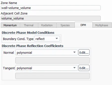
For walls BC is set as no slip and discrete phase BC is set as reflect.
Simulations are ran mainly 2 cases:
1. For a inlet velocity of 3 m/s (for both fluid and solid particle) simulations are run by varying the particle diameter from 1 `mu m` to 5 `mu m`and calculating separation efficiency:
a) Particle diameter = 1 `mum`:
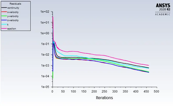
* Residual plot:
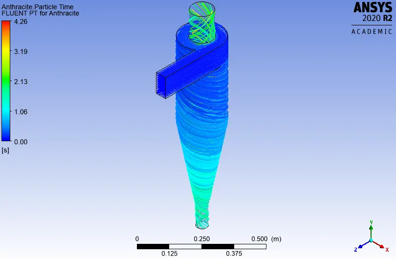
* Anthracite particle time contour:
* Particle_Data:

Separation efficiency = Number of particle trapped/Number of particle tracked
therefore Separation efficiency = 41/124*100 = 33.06 %
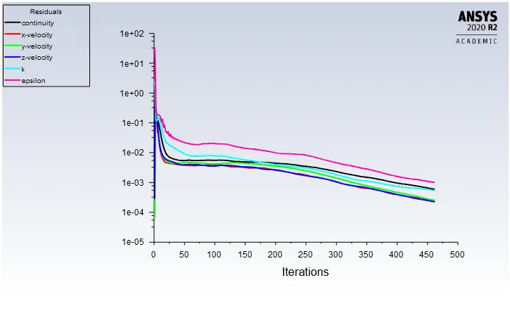
b) Particle diameter = 2 `mu m`:
* Residual plot:
* Anthracite particle time contour:
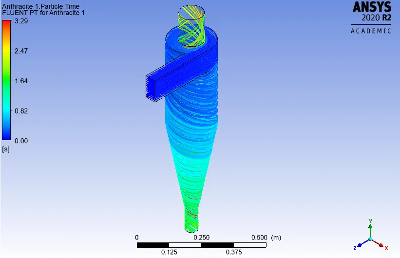
* Particle_Data:

Separation efficiency = 98/124*100 = 79.03 %
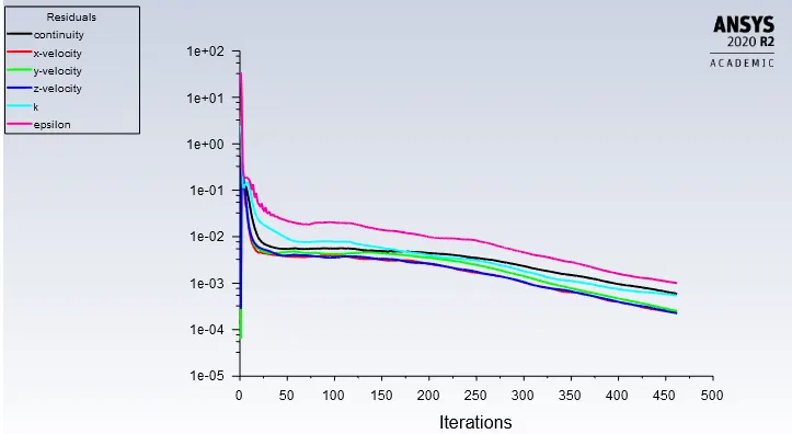
c) Particle diameter = 3 `mu m`:
* Residual plot:
* Anthracite particle time contour:
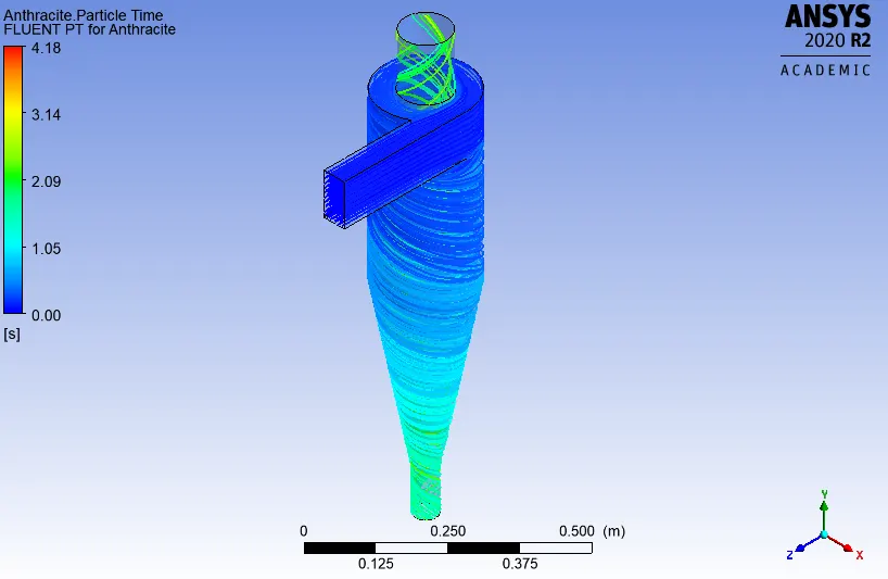
* Particle_Data:

Separation efficiency = 100/124*100 = 80.64 %
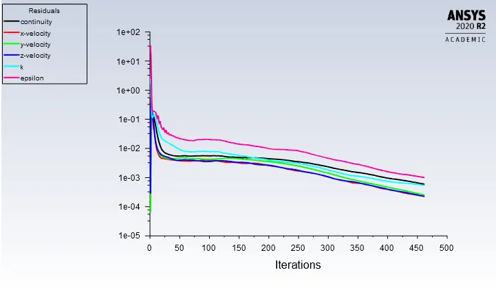
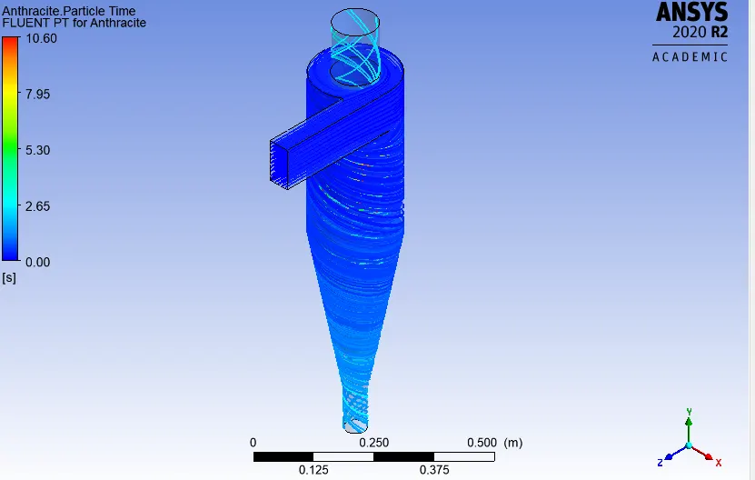
d) Particle diameter = 4 `mu m`:
* Residual plot:
* Anthracite particle time contour:
* Particle_Data:

Separation efficiency = 114/124*100 = 91.93 %
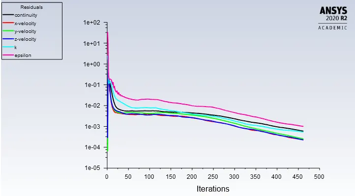
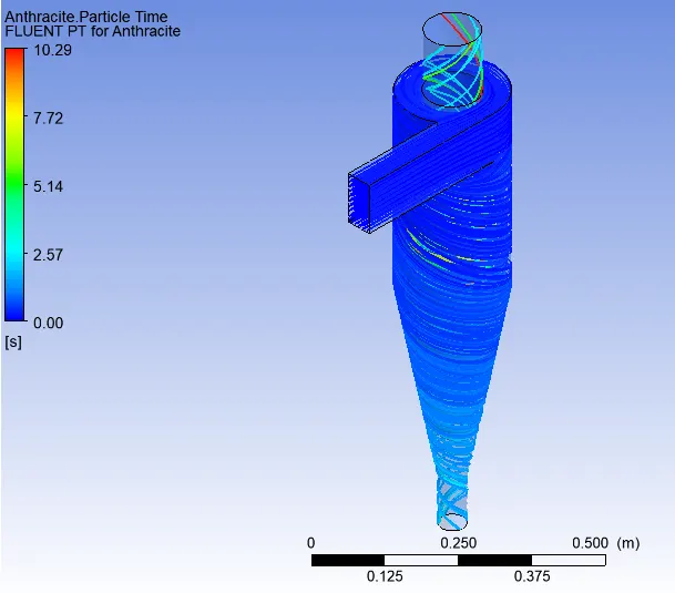
e) Particle diameter = 5 `mu m`:
* Residual plot:
* Anthracite particle time contour:
* Particle_Data:

Separation efficiency = 114/124*100 = 91.93%
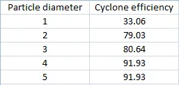
Above result is summarised in table below,
2. For particle diameter of 5 `mu m` to run the simulation for varying velocity of 1 m/s to 5 m/s (Same for both particle and fluid) and hence calculating the separation efficiency and pressure drop:
a) Velocity = 1 m/s:
* Residual plot:
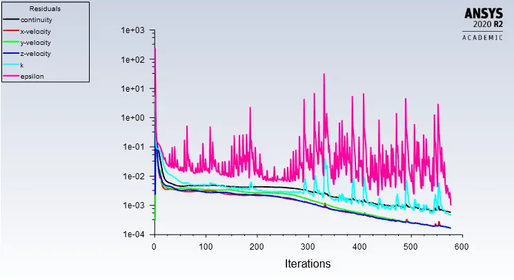
* Anthracite particle time contour:
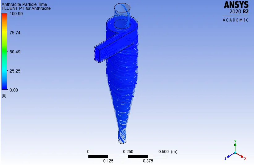
* Particle_Data:

Separation efficiency = 6/124*100 = 4.83%
* Total pressure at inlet and outlet's:
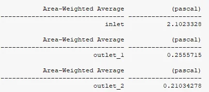
pressure drop = 2.102-0.2103 = 1.8917 Pa.
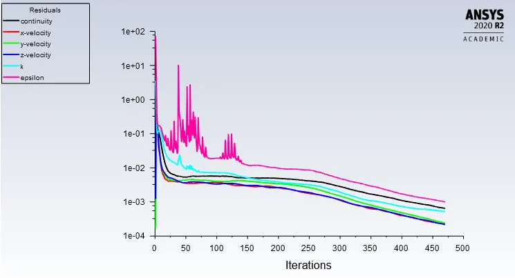
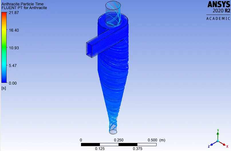
b) Velocity = 2 m/s:
* Residual plot:
* Anthracite particle time contour:
* Particle_Data:

Separation efficiency = 51/124*100 = 41.12%
* Total pressure at inlet and outlet's:
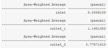
pressure drop = 8.5849-0.7787 = 7.8062 Pa.
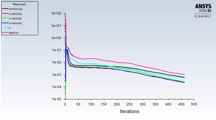
c) Velocity = 3 m/s:
* Residual plot:
* Anthracite particle time contour:
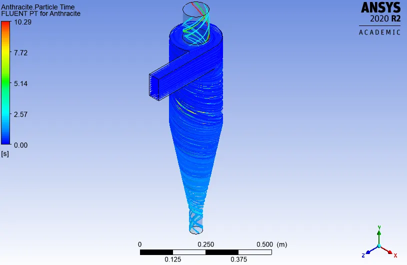
* Particle_Data:

Separation efficiency = 114/124*100 = 91.93%
* Total pressure at inlet and outlet's:
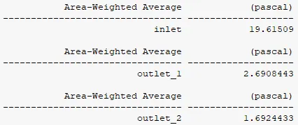
pressure drop = 19.615-1.692 = 17.923 Pa.
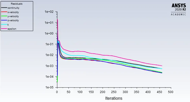
d) Velocity = 4 m/s:
* Residual plot:
* Anthracite particle time contour:
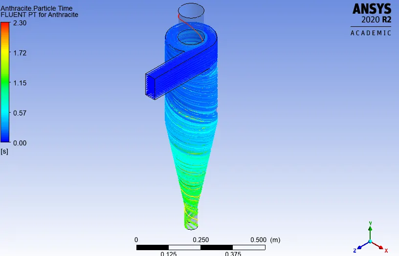
* Particle_Data:
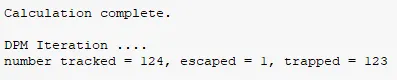
Separation efficiency = 123/124*100 = 99.19%
* Total pressure at inlet and outlet's:
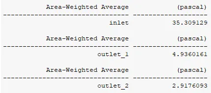
pressure drop = 35.309-2.917 = 32.392 Pa.
e) Velocity = 4 m/s:
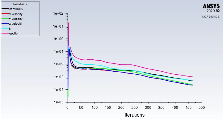
* Residual plot:
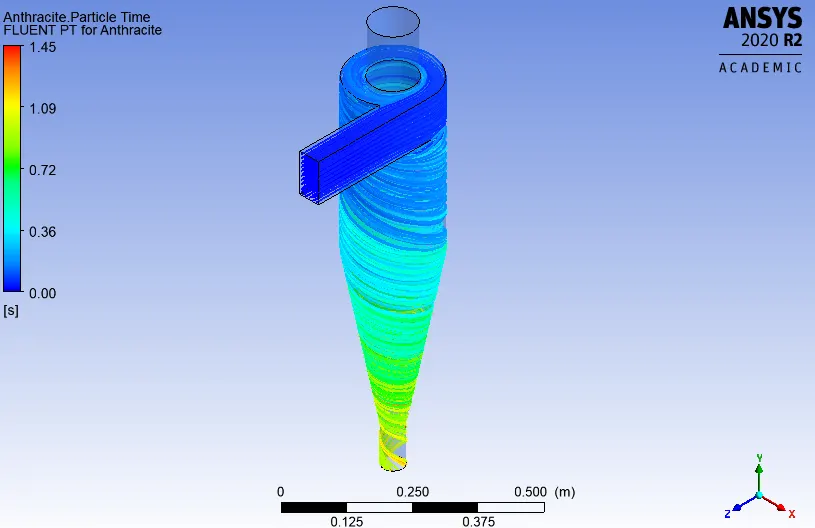
* Anthracite particle time contour:
* Particle_Data:
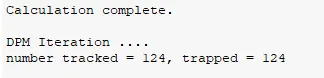
Separation efficiency = 124/124*100 = 100%
* Total pressure at inlet and outlet's:
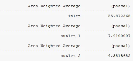
pressure drop = 55.872-4.381 = 51.491 Pa.
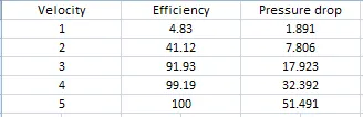
Above result is summarised in table below,
#CONCLUSION:
* From first case we can clearly observe that as the particle diameter increases the efficiency is also increasing. Increase in efficiency is not linear but for the given size of cyclone separator efficiency as high as 91% can be achieved for a particle diameter of 5 `mu m` entering with a velocity of 3 m/s.
* From second case we can clearly observe that as velocity increases both efficiency and pressure drop increases. 100% efficiency can be achieved for the given size of cyclone separator in filtering out particle of size 5 `mu m` at a velocity of 5 m/s.