Cyclone Separator Challenge
Objective:
- To perform analysis on cyclone seperator and calculate the seperation efficieny and pressure drop.
- To study different emperical formulas used to calculate the cyclone seperator efficiency.
- To perform an analysis on cyclone seperator model and understanding its working.
- To understand the effects of velocity and particle size on cyclone seperator efficieny and pressure drop.
Introduction:
Cyclone sperators are seperation devices that remove the particulate matter from flue gases using th eprinciple of inertia. Cyclone seperators are one of the many air pollution control devices known as pre cleaners since they easily remove the larger peices of particulate matter. A large number of cycloner can be operated in parallel and thus the system can be called as multicyclone.
Working:
Cyclone sperators work as a centrifuge and with the continous feed of dirty air. In a cyclone seperator the dirdy gases are fed into a chamber which thus creates a spiral vortex, similar to tornado. The lighter particle in the tornado have less inertia and so it is easier for them to get influenced by the inertia and travel them up. Other than lighter particles heavy particvles have higher inertia and are nopt easily influenced by the vortex. Since the particles with large particle have difficulty following the high speed motion the particles hit the wall and thus drop down the collection hopper. These chambers are shaped like inverted cones to promote the collection of the particles at the bottom of the container. The cleaner flue gases escapes out the tp of the chamber.
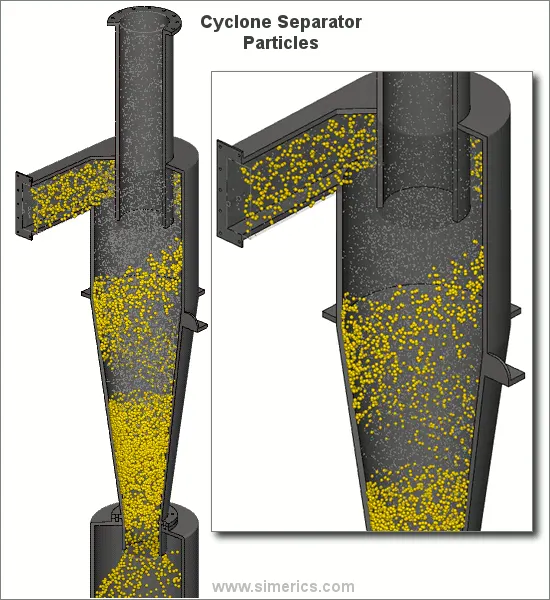
Generally cyclones can be seperate particles larger than that of 10microns in diameter. However there do exist some high efficiency cyclone seperator that are said to effective on particle size upto 2.5 microns. However these cyclones are not effective on large particle sizes. For the particulate sizes larger than that of the 200 microns in size gravity settling chambers or momentum seperators are better option for seperation.
Out of all the seperation devices the cyclone are most inexpensive ones. They are generally used as pre treatment before the flue gases enters more effectiove pollution control devices. Thus trhe cyclone seperators are used as the rough seperators before the flue gases reaches the final filteration stage.
Effectiveness
Cyclone seperators generally remove particles in between the range of 50-99% of the particles in the flue gases but it depends upon the size of the paricles. If the particles are lighter in weight and have less diameter, lower level of particles are seperated from the. Thus cyclones work best on the particles with the larger particle sizes.
There are various advantages of installing a cyclone seperator ranging from their low cost and low maintainence. This is due to the simple design and the lack of the moving parts in the device. Further the removed particles is collected in a box when dry which can is very easy to dispose. Other han this tthses machines are very compact and take very less storage area. Apart from the advantages there are various disadvantages of the cyclone ranging which are the standard models of the cyclone are not able to seperate the particulate matter lower than the size of the 10 microns. Further these cyclone are not capable of hadling sticky and tacky materials.
There are various empherical models for the cyclone seperator efficiceny;
4.1 lozia and leith model:
This method is modified barth model which is developed with the help of the force balance. This model assumes that two forces are applied on the particle in the vortex one is centrifugal force(Z) and the second is the flow resistance(W). The collection efficinency `etaunderset(i)()` of the paricle diameter `dunderset(p i)()` can be calculated from teh given formula:
`etaunderset(i)()=frac{1}{1+(frac{dunderset(pc)()}{dunderset(p i)()})^beta`
`beta` here is the expression for the slope parameter derived based on teh satistical method of experimental data of a cyclone with D=0.25m is given by:
`beta=0.62-0.87ln(frac{dunderset(pc)()}{100})+5.21ln(frac{ab}{D^2})+1.05[ln(frac{ab}{D^2})]^2`
wgere `dunderset(pc)()`is given by the 50% cut size of teh barth
`dunderset(pc)()=[frac{9muQ}{pirhounderset(p)()Zunderset(c)()(vunderset(tmax)())^2}]^0.5`
where core length `Zunderset(c)()` and the cre diameter `Zunderset(c)()`is given by
`Zunderset(c)()=(H-S)-[frac{H-S}{(frac{D}{B})-1}][(frac{dunderset(c)()}{B})-1], dunderset(c)()gtB`for
`Zunderset(c)()=H-S`
`dunderset(c)()=0.47D(frac{ab}{D^2})^(-0.25)(frac{Dunderset(e)()}{D})^1.4`
4.2 Li and Wang Model
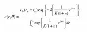
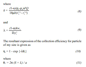
This model includes the particle bounce and re intermaintmentand the turbulent dffusion ant the cyclone wall. A two dimensional model is obtained and tehe model is based on the following assumptions:
The radial particle velocity and the radial concemtration profile are not constant for the uncollected particles within the cyclone.
Boundary conditions with the consideration of the turbulesnt diffusion coefficient and particle bounce reintraintment on the cyclone walls are:
`c=cunderset(a)(), at theta=0`
`Dunderset(r)()frac{delc}{delr}=(1-alpha)wc, atr=D/2`
the tangential velocity is related to the cyclone by:
`muR^n=constant`
4.3 Koch and Litch Model:
This theory recognised the inherently turbulent model of cyclones and the distribution of the gas residence within the cyclone. They described the particle motion in the entry and the collection regions with the following assumptions:
The tangential velocity of the particle is equal to the tangential velocity of teh flue gas.
A force balance and the equation on the particle collection yeilds the following grade efficicency:
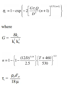
G is a factor related to teh configuration of the cyclone, n is related to the vortex and tau is related to teh relaxation term.
4.4 Lapple Model:
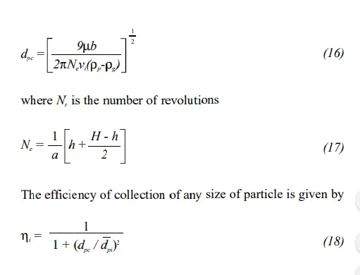
It was developed based on the force balance without considering teh flow resistance. It is assumed that the particle in the cyclone is evenly distributed across the opening. The particle that travels from teh inlet to teh half width to the wall in teh cyclone is collected with 50% efficiency. The semiempherical relationship developed by the lapple to calculate the 50% diameter is given by:
Cyclone Seperator Simulation:
- Modeling
- Meshing
- Pre-processing
- Setting up Physics
- Post processing
1.) Modeling of the Cyclone Seperator
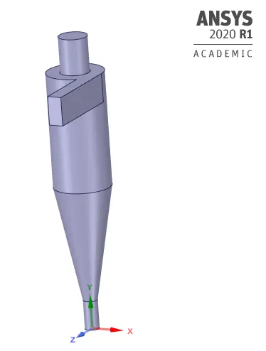
The CAD model for the cyclone is first prepared in any CAD software which then can be imported in the spaceclaim.
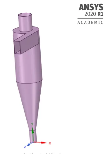
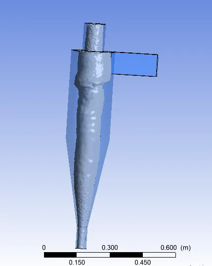
The volume is then extracted from this model after minor repairing the model by removing the extra edges. The extracetd volume can be seen below:
2.Meshing
After extravting the volue th e model is than imported to mechanical modile for meshing here the mesh size is set as 6mm and the rest of the parametrs are kept default and the mesh is then generated as shown below:
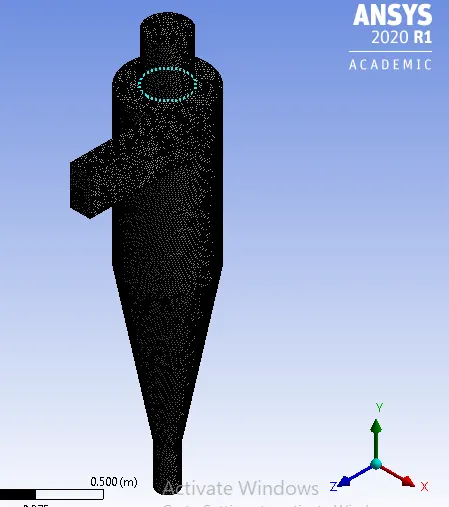
The different faces are then given there names in the body and can be see below:
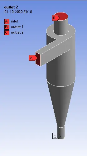
The numer of nodes are 89541 and the elemnts for this mesh are 459543. The mesh quality can be seen below:
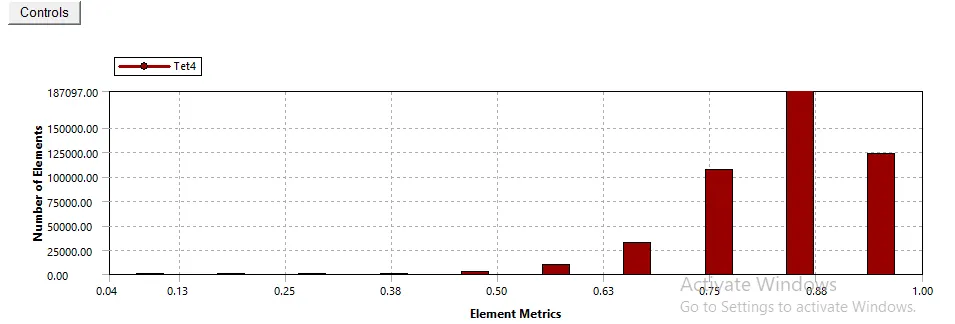
Here it can be seen that the maximum particles rae in 0.88 percent range thus the mesh hasd quite good quality and will lead to less number of errors.
3. Setting up Physics and Solving:
The following steps were performed for setting up the physics in the fluent setup:
The mesh was checked
Upon getting no errors the solver was setup as pressure based solver with steady state and teh gravity was enabled with the value of -9.81 in the y direction.
Viscous Model: k-epsilon model(RNG-swirl dominated flow)
Discrete Phase Modeling was turned on and the interaction with continous phase was turned on and DPM was updated at every flow iteration.
Surface injection was created with anthracite as the injected particle. The diamter was provided in range of 1microns to 5 microns as per the case.
Boundary Conditions:
Inlet: 1-5m/s DPM: Reflect
Outlet 1: Gauge Pressure: 0, DPM: Escape
Outlet 2: Gauge Pressure: 0, DPM: Trap
Walls: DPM Reflect
Methods:
Momentum: First Order Upwind
Turbulent Kinetic Energy: Second Order Upwind
Turbulent Dissipation Rate: Second Order Upwind
Initialisation: Standard
Compute from: Inlet
The simulation is then started for teh around 500 iterations and it sis checked weather the solution has converged.
Post Processing:
We analysed the efficiency of the cyclone seperator for the various particle sizes ranging from 1 microns to 5 microns for the inletr velocity of 5m/s.
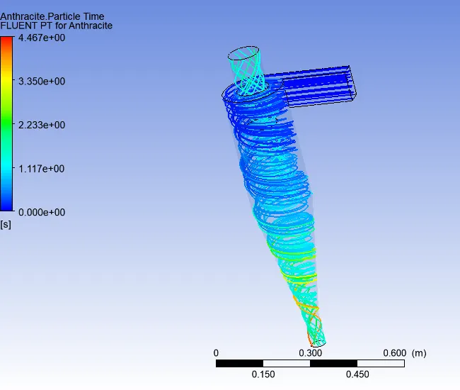
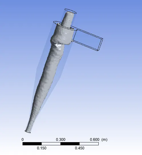
The results for the cyclone of with the particle dia of 1 micron can be seen below:
1. Particle time
2. Vortex
The animation for the particle can be seen here https://drive.google.com/file/d/1Uy_S9raD02lvG_mIMmB4RK3N_B74QIvU/view?usp=sharing.
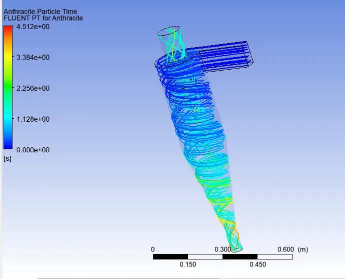
The results for the cyclone of with the particle dia of 2 micron can be seen below:
1. Particle time
2. Vortex
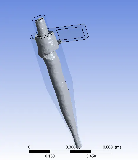
The animation for the particle can be seen here https://drive.google.com/file/d/1IwJmI_KNV2t4BkCvpS_8pmz2HIF0L_DI/view?usp=sharing
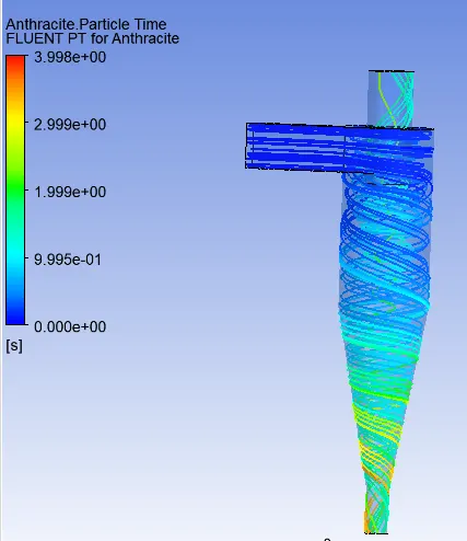
The results for the cyclone of with the particle dia of 3 micron can be seen below:
1. Particle time
2. Vortex
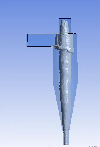
The animation for the particle can be seen here https://drive.google.com/file/d/1KMQKJkhtBJvlGGlYNSuiTLo6ilsXxwNg/view?usp=sharing
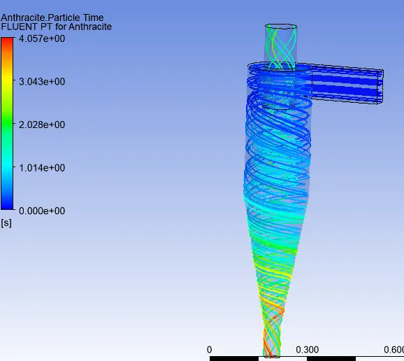
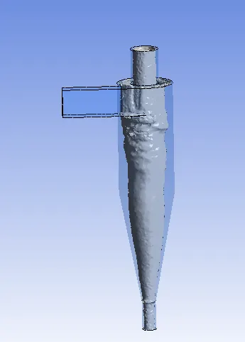
The results for the cyclone of with the particle dia of 4 micron can be seen below:
1. Particle time
2. Vortex
The animation for the particle can be seen here https://drive.google.com/file/d/19XaYnZDbB9Mfp-BQYgfHyLS5WCkCDvmA/view?usp=sharing
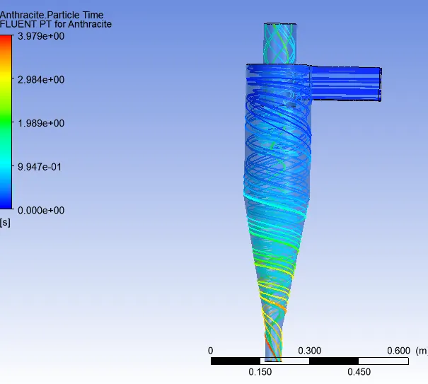
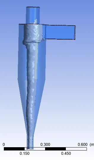
The results for the cyclone of with the particle dia of 5 micron can be seen below:
1. Particle time
2. Vortex
The animation for the particle can be seen here https://drive.google.com/file/d/12StaTYm36IduSvXU4AbFt-yyQN6-cs52/view?usp=sharing.
The particle seperation efficiency can be seen below:
|
Particle Size (microns) |
Tracked | Escaped | Trapped | Incomplete | Efficiency | Mass Flow at Inlet (kgs^-1) | Mass Flow at Outlet 1 (kgs^-1) | Mass Flow at Outlet 2 (kgs^-1) |
| 1 | 350 | 159 | 187 | 4 | 0.534 | 0.018375 | 0.0140526 | 0.0043238 |
| 2 | 350 | 148 | 196 | 6 | 0.56 | 0.018375 |
0.0140526 |
0.00432332 |
| 3 | 288 | 116 | 171 | 1 | 0.59 | 0.018375 | 0.014011 | 0.00436404 |
| 4 | 288 | 95 | 193 | 0 | 0.67 | 0.018375 | 0.014011 | 0.00436404 |
| 5 | 288 | 136 | 151 | 1 | 0.52 | 0.018375 | 0.014011 | 0.00436404 |
Case II Effect of Velocity
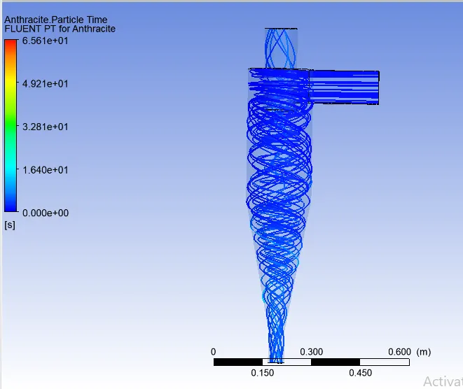
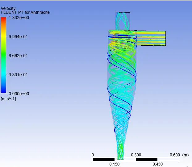
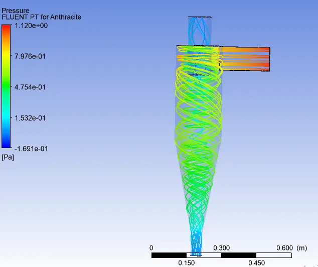
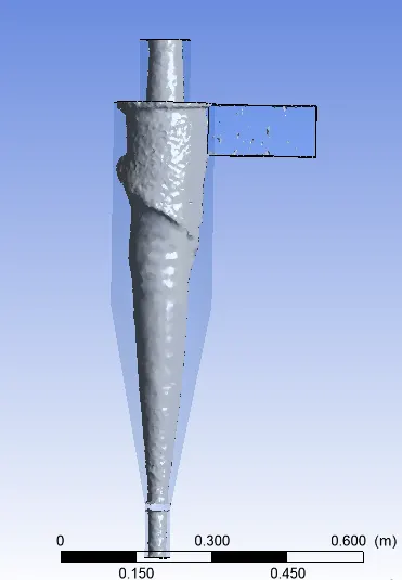
In this case we will check the effect of velocity on a acyclone seperator keeping the particli size as common. The velocity will limit from 1ms to 5ms.
The results for the velocity of 1ms and 5 microns can be seen below:
1 Particle Time
2. Velocity
3. Pressure:
4. Vortex
The animation for this simulation can be seen here https://drive.google.com/file/d/1YYmoyMc3RWNnRW788mEoLuQZ-7_9rPWb/view?usp=sharing
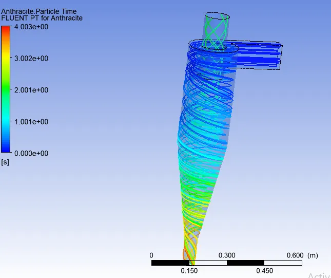
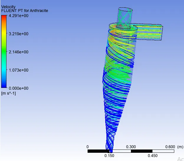
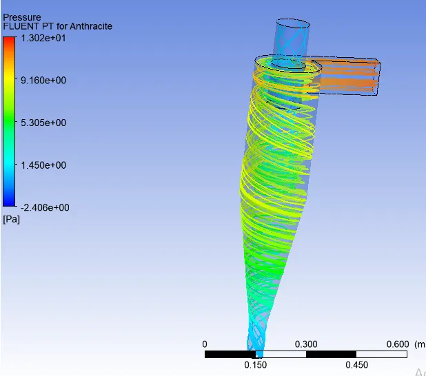
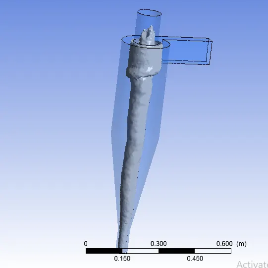
The results for the velocity of 3ms and 5 microns can be seen below:
1 Particle Time
2. Velocity
3. Pressure:
4. Vortex
The animation for this simulation can be seen here https://drive.google.com/file/d/14H9shRJIrr98-2GJ2QwobIpVOF021Gib/view?usp=sharing
The results for the velocity of 4ms and 5 microns can be seen below:
1 Particle Time
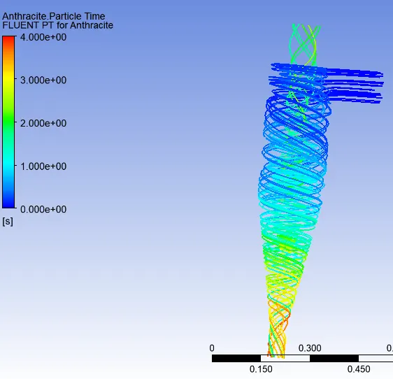
2. Velocity
3. Pressure:
4. Vortex
The animation for this simulation can be seen here https://drive.google.com/file/d/14H9shRJIrr98-2GJ2QwobIpVOF021Gib/view?usp=sharing
The results for the velocity of 5ms and 5 microns can be seen below:
1 Particle Time
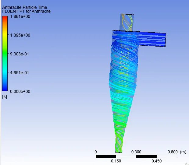
2. Velocity
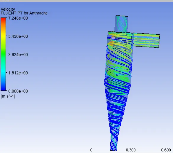
3. Pressure:
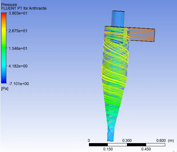
4. Vortex
The animation for this simulation can be seen here https://drive.google.com/file/d/1Auy9T9jEW_4DuGvCT9PPazJC52Ai-X_l/view?usp=sharing
The particle seperation efficiency for different velocities can be seen below:
| Velocity (ms^-1) | Tracked Particles | Escaped Particles | Trapped Particles | Incomplete Particles | Mass Flow Inlet | Mass Flow Outlet 1 | Mass Flow Outlet 2 | Total Pressure Drop(Pa) | Efficiency |
| 1 | 288 | 137 | 112 | 39 | 0.006125 | 0.00454953 | 0.00157547 | 1.0782 | 0.38889 |
| 2 | 288 | 104 | 180 | 4 | 0.01225 | 0.00925058 | 0.00299942 | 4.89277 | 0.625 |
| 3 | 288 | 67 | 221 | - | 0.018375 | 0.01404 | 0.00436403 | 11.8396 | 0.76736 |
| 4 | 288 | 50 | 238 | - | 0.024685 | 0.01853 | 0.00624 | 23.4678 | 0.826 |
| 5 | 288 | 41 | 247 | - | 0.030625 | 0.0235384 | 0.00708661 | 34.1739 | 0.8612 |
Conclusion
- It can be noticed that with increase in the paricle size the efficiency of the cyclone also increases. Furthermore it can also be noted that the efficiency of cyclone seperator below particle size of 3 microns is very poor thus it is not suited for the particles below 3 or 4 microns.
- For the same velocity the total pressure drop remains the same but when the particle size increses teh number of particles trapped also increases thus incresing th efficiency of the cyclone.
- For different velocitites it can be noted that the efficiency increses with increase in the velocity of the inlet. Further it should also be noted that incresing the velocity will lead to higher power consumption of the cyclone seperator.
- The efficiency of the cyclone seperator depens upon the pressure drop amont the inlets and the outlets. Thus higer the pressure drp higher the efficiency. Incresing the pressure at the inlet will lead to higher power consumption.