Cyclone Separator Challenge
Aim:- To perform analysis on cyclone separator and calculate the separation efficiency and pressure drop.
Introduction of cyclone separator: Cyclones are devices that employ a centrifugal force generated by a spinning gas stream to separate particles from the carrier gas. Their simple design, low maintenance costs,
and adaptability to a wide range of operating conditions such as sizes and flow rates make cyclones one of the most widely used particle removal devices. By using suitable materials and methods of construction, cyclones may be adapted for use in extreme operating conditions: high temperature, high pressure, and corrosive gases. Cyclones are important particle removaldevices in both engineering and process operations.
#Description about Emperical Models used for calculation of Cyclone Separator Efficiency:
1.Iozia and Leith Model:
Iozia and Leith logistic model is a modified version of Barth Model, which is developed based on force
balance.The model assumes that a particle carried by the vortex endures the influence of two forces: a
centrifugal force, Z and a flow resistance, W. The collection efficiency of particle diameter dpi can be
calculated from
`eta=(1)/(1+(d_(pc)/d_(p1))^beta`
`beta` is an expression for slope parameter derived based on the statistical analysis of experimental
data of a cyclone with D = 0.25 m given as
`beta =0.62−0.87 ln ( d_(pc)/ 100 ) +5.21 ln ( (ab )/(D2)) +1.05 ( ln ((ab) /(D2))^ 2)`
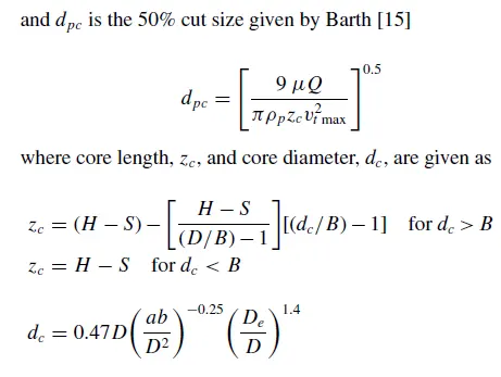
and dpc is the 50% cut size given by Barth.
2.Li and Wang Model
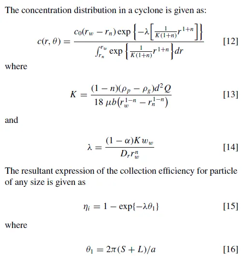
The Li and Wang model includes particle bounce or re-entrainment and turbulent diffusion at the
cyclone wall. A two-dimensional analytical expression of particle distribution in the cyclone is obtained. Li
and Wang model was developed based on the following assumptions:
• The radial particle velocity and the radial concentration profile are not constant for uncollected
particles within the cyclone.
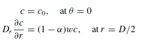
• Boundary conditions with the consideration of turbulent diffusion coefficient and particle bounce re-
entrainment on the cyclone wall are:
- The tangential velocity is related to the radius of cyclone by: `uR^n` = constant`
3.Koch and Licht Model
Koch and Licht collection theory recognized the inherently turbulent nature of cyclones and the
distribution of gas residence times within the cyclone. Koch and Licht described particle motion in the
entry and collection regions with the additional following assumptions:
• The tangential velocity of a particle is equal to the tangential velocity of the gas flow, i.e. there is no
slip in the tangential direction between the particle and the gas.
• The tangential velocity is related to the radius of cyclone by: `uR^n` = constant.
A force balance and an equation on the particles collection yields the grade efficiency `eta`
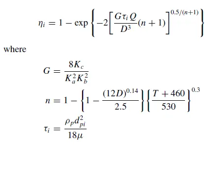
G is a factor related to the configuration of the cyclone, n is related to the vortex and `tau` is the relaxation term.
4.Lapple Model
Lapple modelwas developed based on force balance without considering the flow resistance. Lapple
assumed that a particle entering the cyclone is evenly distributed across the inlet opening. The particle
that travels from inlet half width to the wall in the cyclone is collected with 50% efficiency. The semi
empirical relationship developed by Lapple to calculate a 50% cut diameter, dpc, is
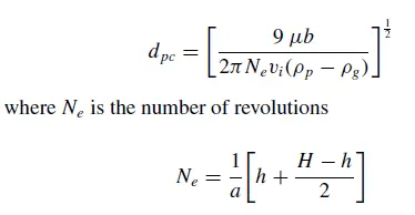
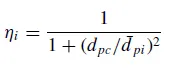
The efficiency of collection of any size of particle is given by
--------------------------------------*************************************--------------------------
Solving & Modelling approach:
Geometry Preparation:
1-Geometry is imported in spaceclaim.
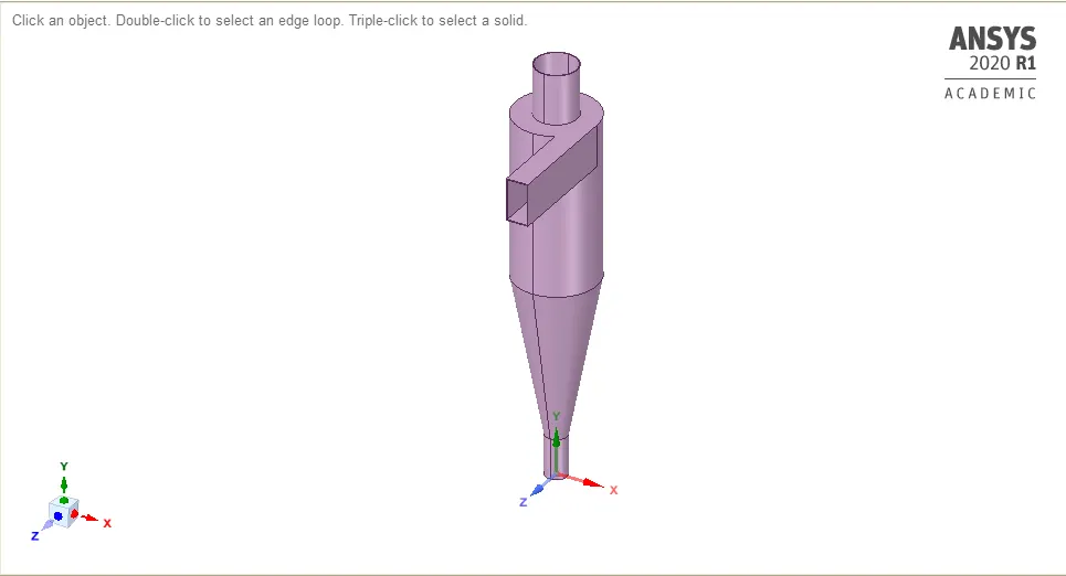
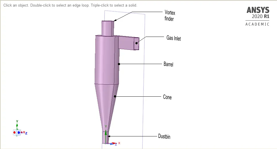
2.Then fluid volume is extracted with the use of Tool-Volume Extract.
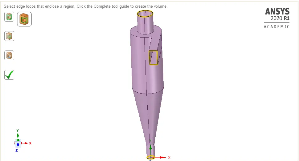
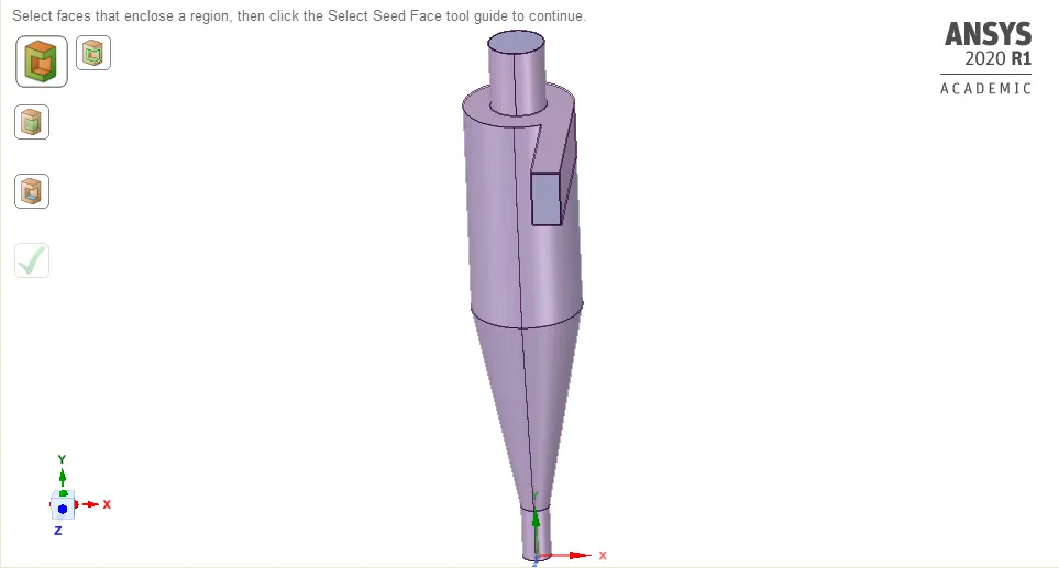
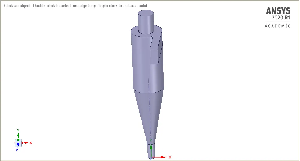
3-Extracted fluid volume.
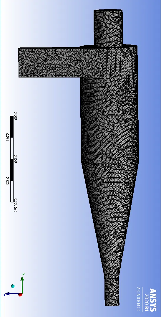
#Meshing:
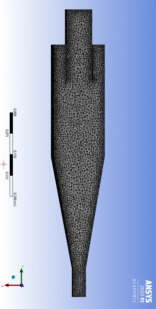
Global Element size-----------0.00535 metre
Face sizing (at Gas Inlet)----0.005 metre
#Setup:
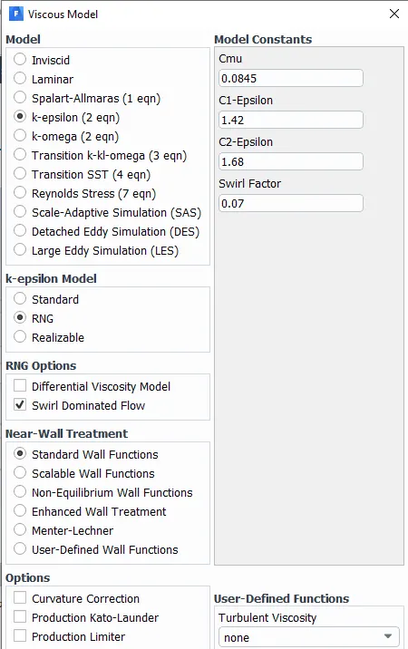
Viscous Model used-K epsilon
----Boundary condition set up for this case.
DPM setting:
Gas Inlet and wall:- Reflect
Outlet1(Top)/Vortex finder:- Escape
Outlet2(Bottom/dustbin) - Trap
----Discrete Phase Model turned on
----Initialization and then Calculation.
#Post process results in CFDPost.
--------------------------------------*************************------------------------------------------
Cases to be discussed:
###All five cases are studied using Unstructured Mesh
Case-1.Particle size--1`mum` and Velocity of Inlet gas and particle velocity equals 3`m/sec`
Case-2.Particle size--3`mum` and Velocity of Inlet gas and particle velocity equals 3`m/sec`
Case-3.Particle size--5`mum` and Velocity of Inlet gas and particle velocity equals 3`m/sec`
Case-4.Particle size--5`mum` and Velocity of Inlet gas and particle velocity equals 1`m/sec`
Case-5.Particle size--5`mum` and Velocity of Inlet gas and particle velocity equals 5`m/sec`
##Specifically Using Structured Mesh
Case-6-Particle size--5`mum` and Velocity of Inlet gas and particle velocity equals 3`m/sec`
-------------------------------------------***********************---------------------------------------
Case-1:-Particle size--1`mum`
Boundary Condition:
Inlet-velocity-inlet-3 m/sec
Outlet1-Pressure outlet-0 bar
Outlet2-Pressure outlet-0 bar
#Solution Methods:
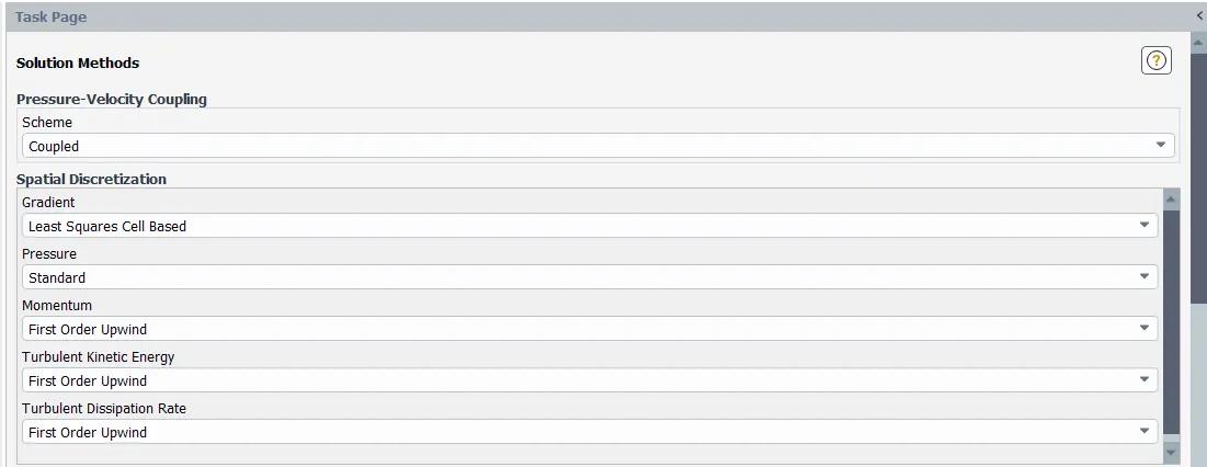
Standard Initialization done and only solution run for 200 iterations.
After solution has become steady ,DPM is turned ON.
DPM Setting:
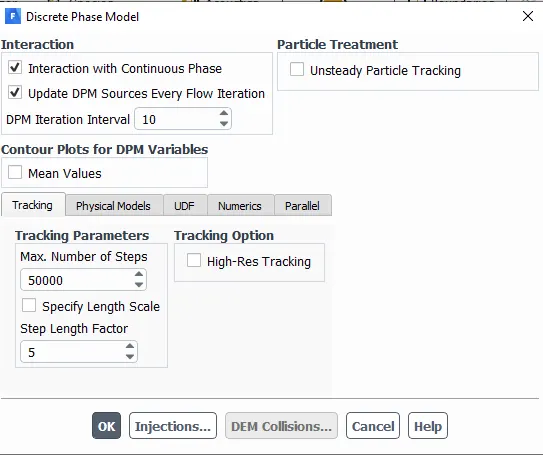
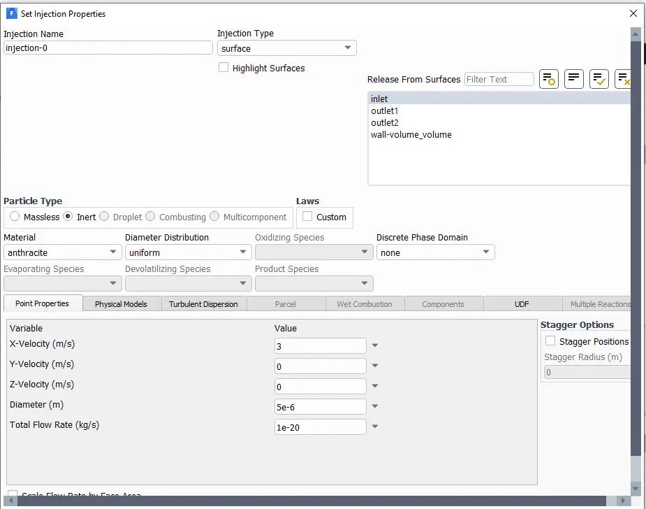
Re-start the calculation till solution converge.
After completion of calculation,export particle track history file.
#Results:
1. Particle Track distribution:
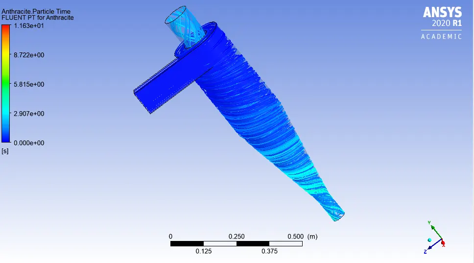
2.Vortex Formation:
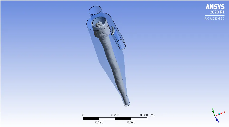
3.Pressure Distribution:
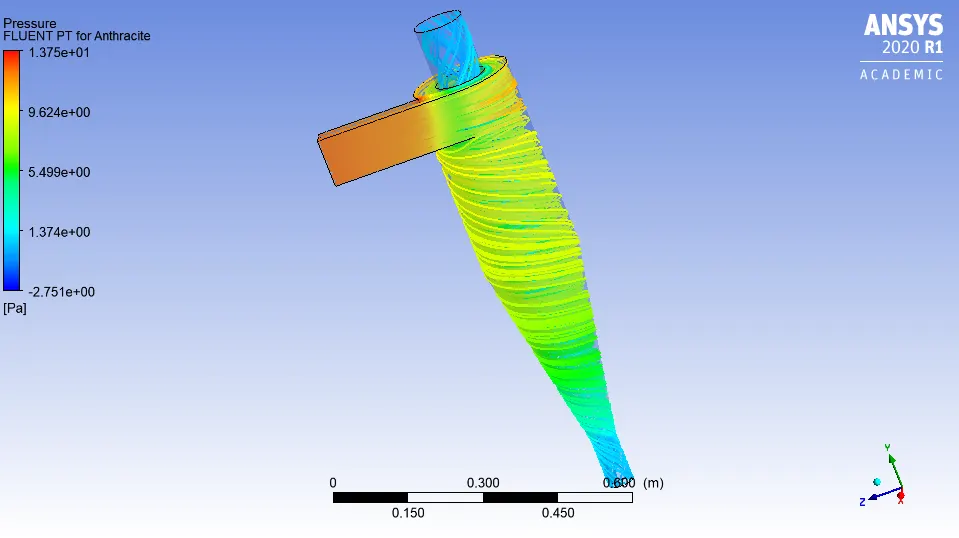
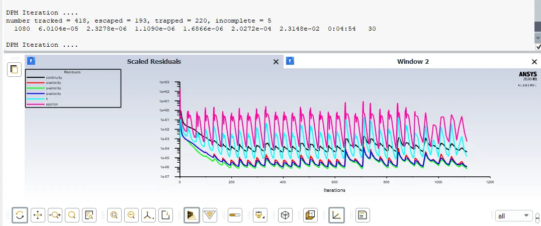
4.Residual plot and Particle track data:
5.Cyclone Separator Efficiency:
Efficiency=`eta`=((Number of Trapped Particle-Incomplete)/(Number of Tracked Particles)
From the figures above;
`eta` = ( 220-5)/(418) ;
`eta`=51.4 %
6.Pressure Drop across Cyclone Seeparator=12.37 Pascal.
------------------------------------------*************************---------------------------------------
Case-2:-Particle size--3`mum`
Boundary Condition:
Inlet-velocity-inlet-3 m/sec
Outlet1-Pressure outlet-0 bar
Outlet2-Pressure outlet-0 bar
-Standard Initialization done and only solution run for 200 iterations.
After solution has become steady ,DPM is turned ON.
#DPM setting
Same as Case-1 ,only change Particle diameter to 3`mum`
Re-start the calculation till solution converge.
After completion of calculation,export particle track history file.
#Results:
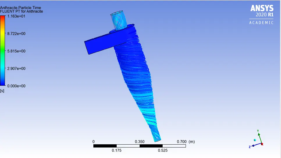
1. Particle Track distribution:
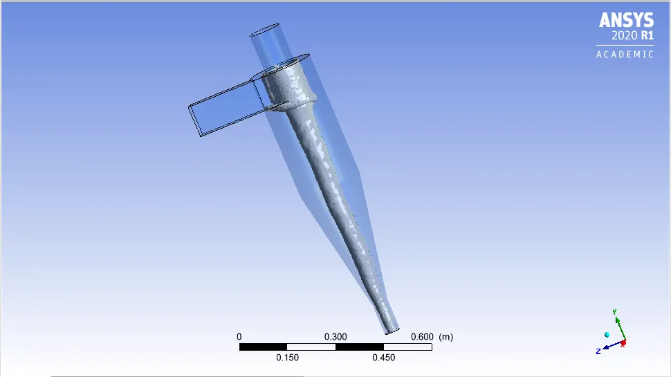
2.Vortex Formation:
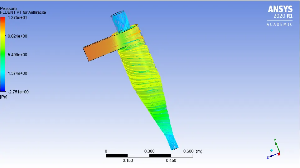
3.Pressure Distribution:
4.Residual plot and Particle track data:
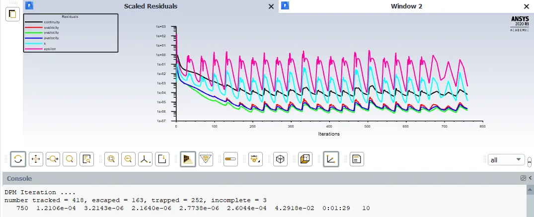
5.Cyclone Separator Efficiency:
Efficiency=`eta`=((Number of Trapped Particle-Incomplete)/(Number of Tracked Particles)
From the figures above;
`eta` = ( 252-3)/(418) ;
`eta`=59.5 %
6.Pressure Drop across Cyclone Seeparator=12.71 Pascal.
------------------------------------------*************************---------------------------------------
Case-3:-Particle size--5`mum`
Boundary Condition:
Inlet-velocity-inlet-3 m/sec
Outlet1-Pressure outlet-0 bar
Outlet2-Pressure outlet-0 bar
-Standard Initialization done and only solution run for 200 iterations.
After solution has become steady ,DPM is turned ON.
#DPM setting
Same as Case-1 ,only change Particle diameter to 5`mum`
Re-start the calculation till solution converge.
After completion of calculation,export particle track history file.
#Results:
1. Particle Track distribution:
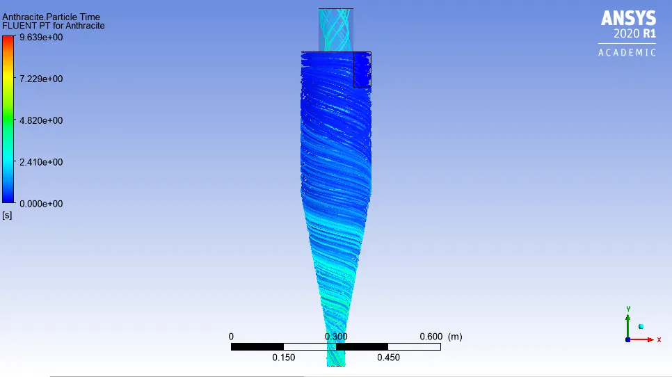
2.Vortex Formation:
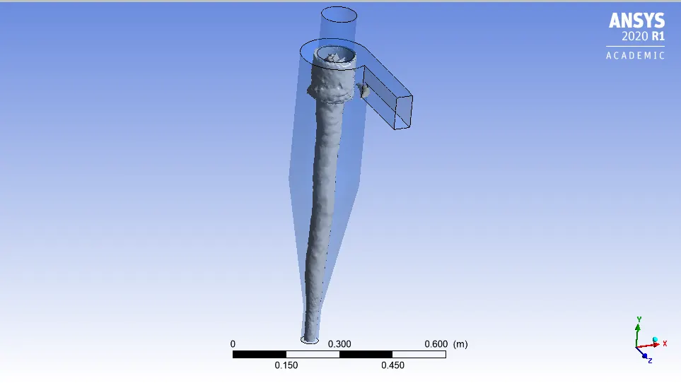
3.Pressure Distribution:
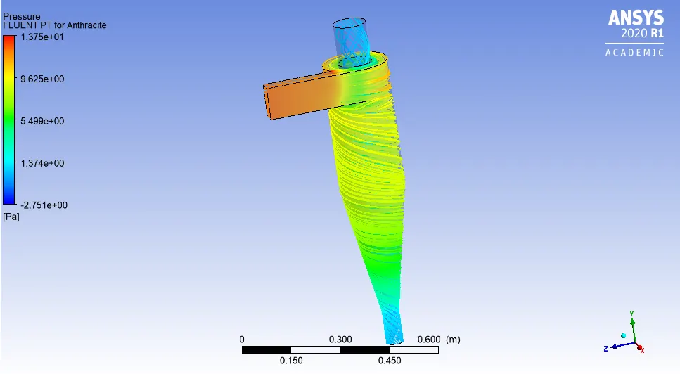
4.Residual plot and Particle track data:
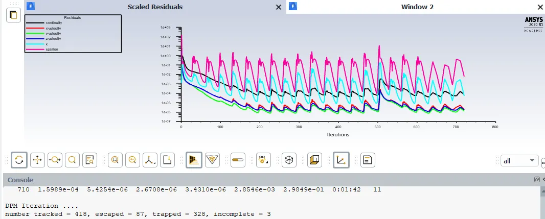
5.Cyclone Separator Efficiency:
Efficiency=`eta`=((Number of Trapped Particle-Incomplete)/(Number of Tracked Particles)
From the figures above;
`eta` = ( 328-3)/(418) ;
`eta`=77.75 %
6.Pressure Drop across Cyclone Seeparator=12.67 Pascal.
------------------------------------**************************---------------------------------
Case-4-(Particle size--5`mum`)
Boundary Condition:
Inlet-velocity-inlet-1 m/sec
Outlet1-Pressure outlet-0 bar
Outlet2-Pressure outlet-0 bar
-Standard Initialization done and only solution run for 200 iterations.
After solution has become steady ,DPM is turned ON.
#DPM setting
Change Particle size to 5`mum` and particle velocity to 1m/sec.
Re-start the calculation till solution converge.
After completion of calculation,export particle track history file.
#Results:
1. Particle Track distribution:
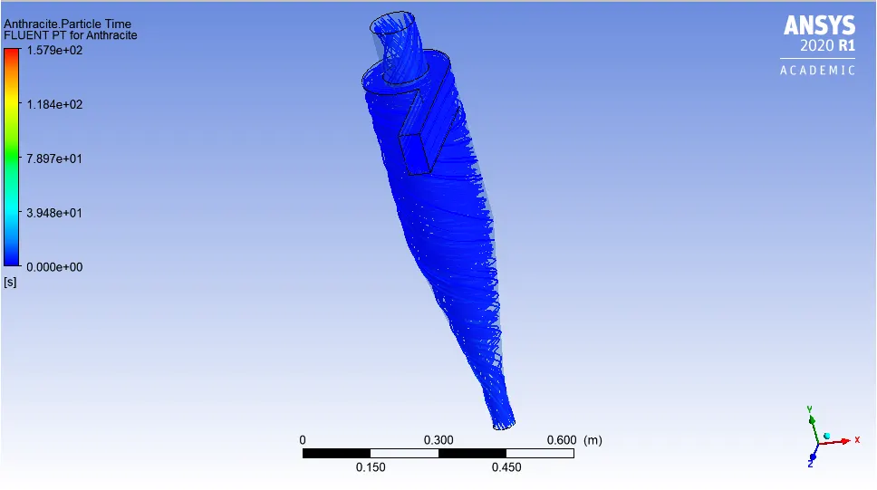
2.Vortex Formation:
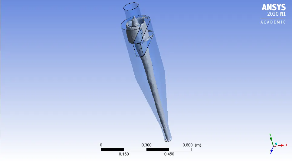
3.Pressure Distribution:
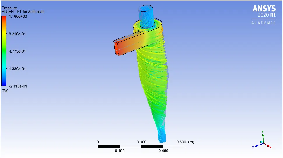
4.Residual plot and Particle track data:
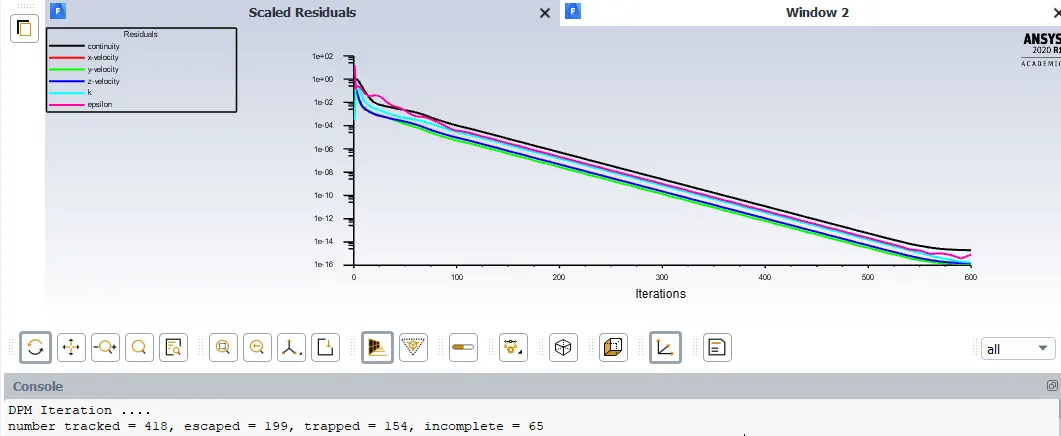
5.Cyclone Separator Efficiency:
Efficiency=`eta`=((Number of Trapped Particle-Incomplete)/(Number of Tracked Particles)
From the figures above;
`eta` = ( 154-65)/(418) ;
`eta`=21.29 %
6.Pressure Drop across Cyclone Seeparator=1.11 Pascal.
-------------------------------------------**************************-----------------------------
Case-5-(Particle size--5`mum`)
Boundary Condition:
Inlet-velocity-inlet-5 m/sec
Outlet1-Pressure outlet-0 bar
Outlet2-Pressure outlet-0 bar
-Standard Initialization done and only solution run for 200 iterations.
After solution has become steady ,DPM is turned ON.
#DPM setting
Change Particle size to 5`mum` and particle velocity to 5m/sec.
Re-start the calculation till solution converge.
After completion of calculation,export particle track history file.
#Results:
1. Particle Track distribution:
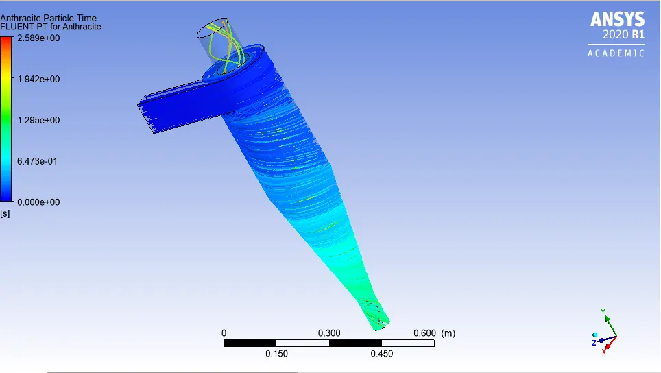
2.Vortex Formation:
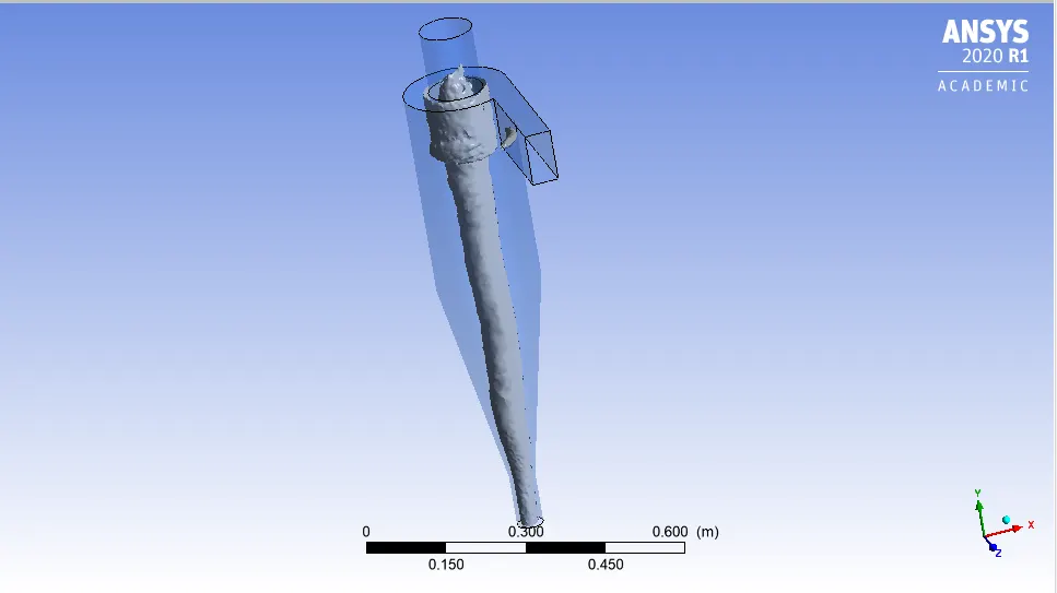
3.Pressure Distribution:
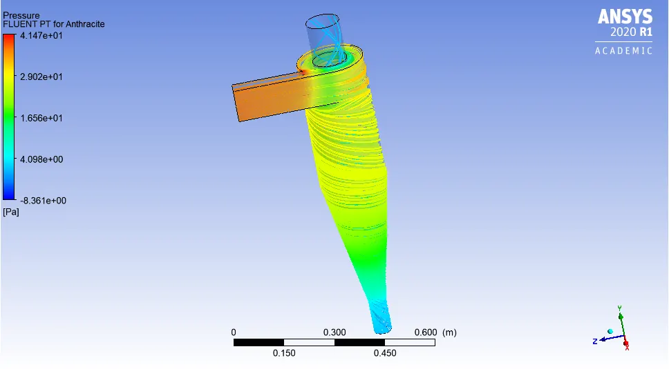
4.Residual plot and Particle track data:
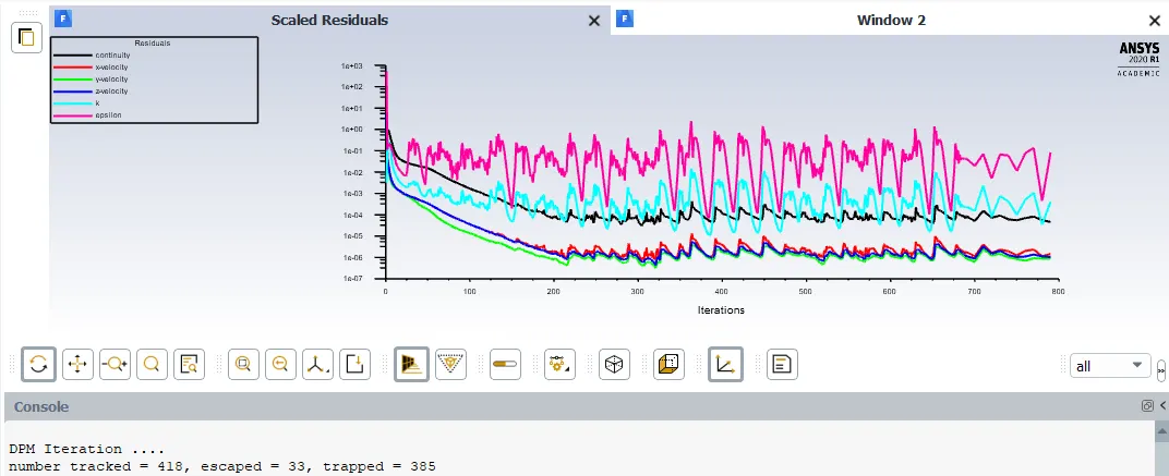
5.Cyclone Separator Efficiency:
Efficiency=`eta`=((Number of Trapped Particle-Incomplete)/(Number of Tracked Particles)
From the figures above;
`eta` = ( 385-0)/(418) ;
`eta`=92.11 %
6.Pressure Drop across Cyclone Seeparator=37.23 Pascal.
-------------------------------------------**************************-----------------------------
Case-6-Particle size--5`mum`
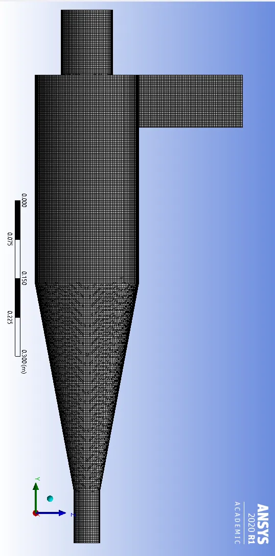
#Mesh:
Boundary Condition:
Inlet-velocity-inlet-3 m/sec
Outlet1-Pressure outlet-0 bar
Outlet2-Pressure outlet-0 bar
-Standard Initialization done and only solution run for 200 iterations.
After solution has become steady ,DPM is turned ON.
#DPM setting
Same as Case-1 ,only change Particle diameter to 5`mum`
Re-start the calculation till solution converge.
After completion of calculation,export particle track history file.
#Results:
1. Particle Track distribution:
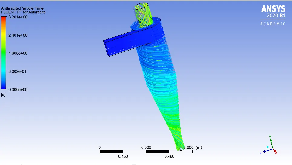
2.Residual plot and Particle track data:
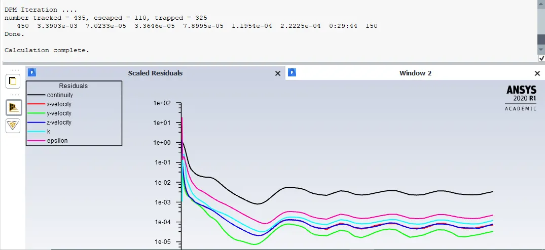
3.Cyclone Separator Efficiency:
Efficiency=`eta`=((Number of Trapped Particle-Incomplete)/(Number of Tracked Particles)
From the figures above;
`eta` = ( 325-0)/(418) ;
`eta`=77.75 %
------------------------------------------**********************---------------------------------
##Conclusion:
1.From the results we have obtained,it is clear that with the increase particle size from `1mum` to `5um` keeping velocity of flow constant ,the efficiency of cyclone separator has increased.Some where also no. of particles recirculated inside also reduced.Efficiency increased means,as particles size was small,due to there light weight they escaped to vortex finder along with the gas or liquid.
2.Second thing,when we kept particle size constant that is `5mum` and increased velocity from 1 to 5 m/s,we observed that-
Again efficiency of separator increases with increase in the velocity.
As the particle travel down the separator ,the particle strike the walls and at the outlet there is significant pressure drop.Pressure drop also increases with increase in the velocity.
3.We tried one case with unstructured and structured mesh having all other parametrs same,though results obtained from structured mesh are better,but in this case we obtained same results as far as efficiency is concerned.