Creation of Multiple viewports, Scaling the drawing and setting in Template in AutoCad
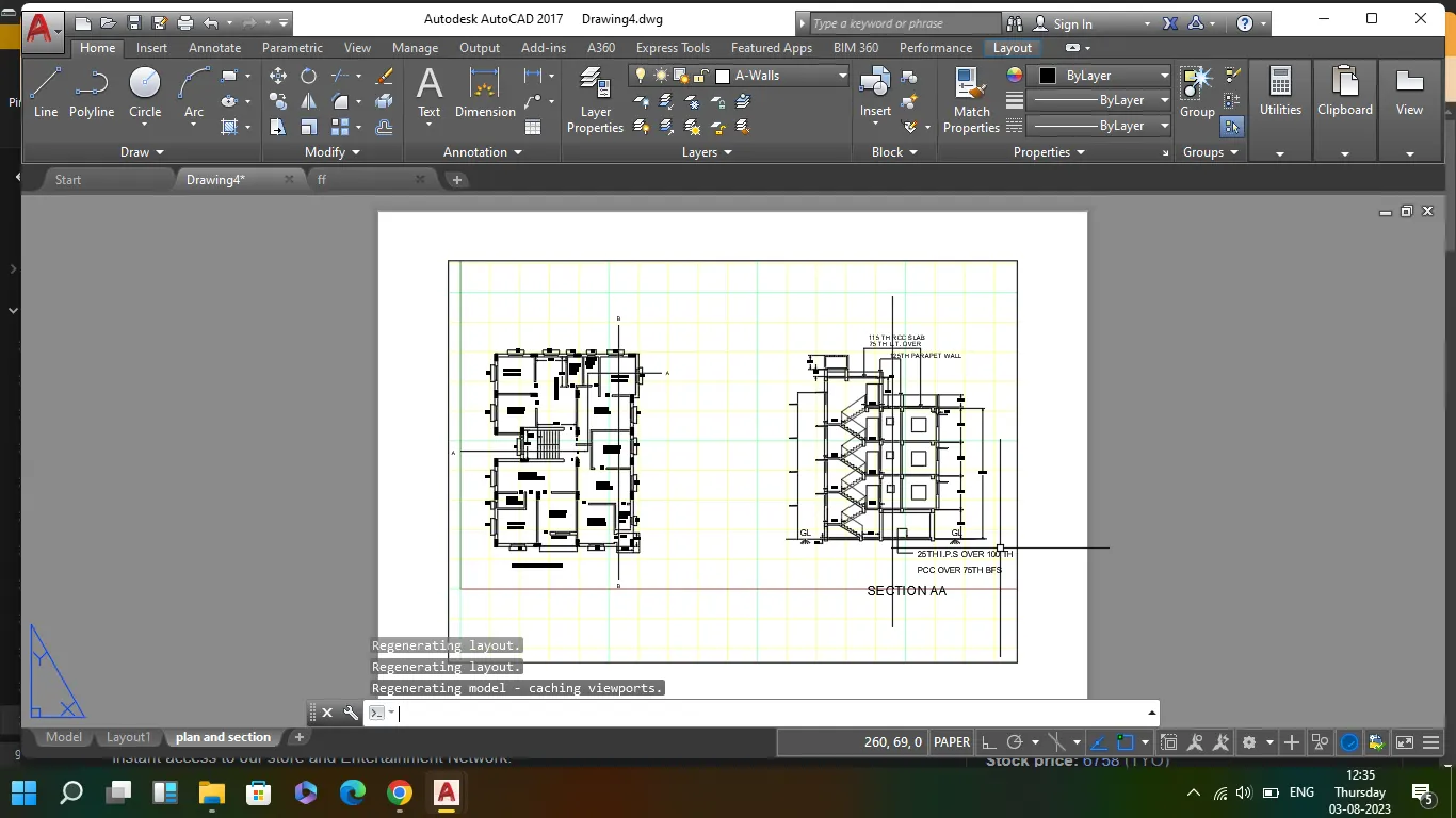
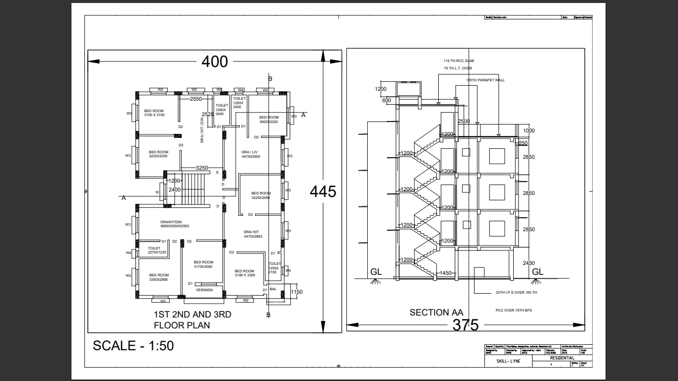
Create a layout of challenge 7 section and plan dwg.
using recqurired command, MV , pagesetup manger, view, scale , plot, model space and paper space
- open challenge 7 drawing, give layout command and give name plan and section
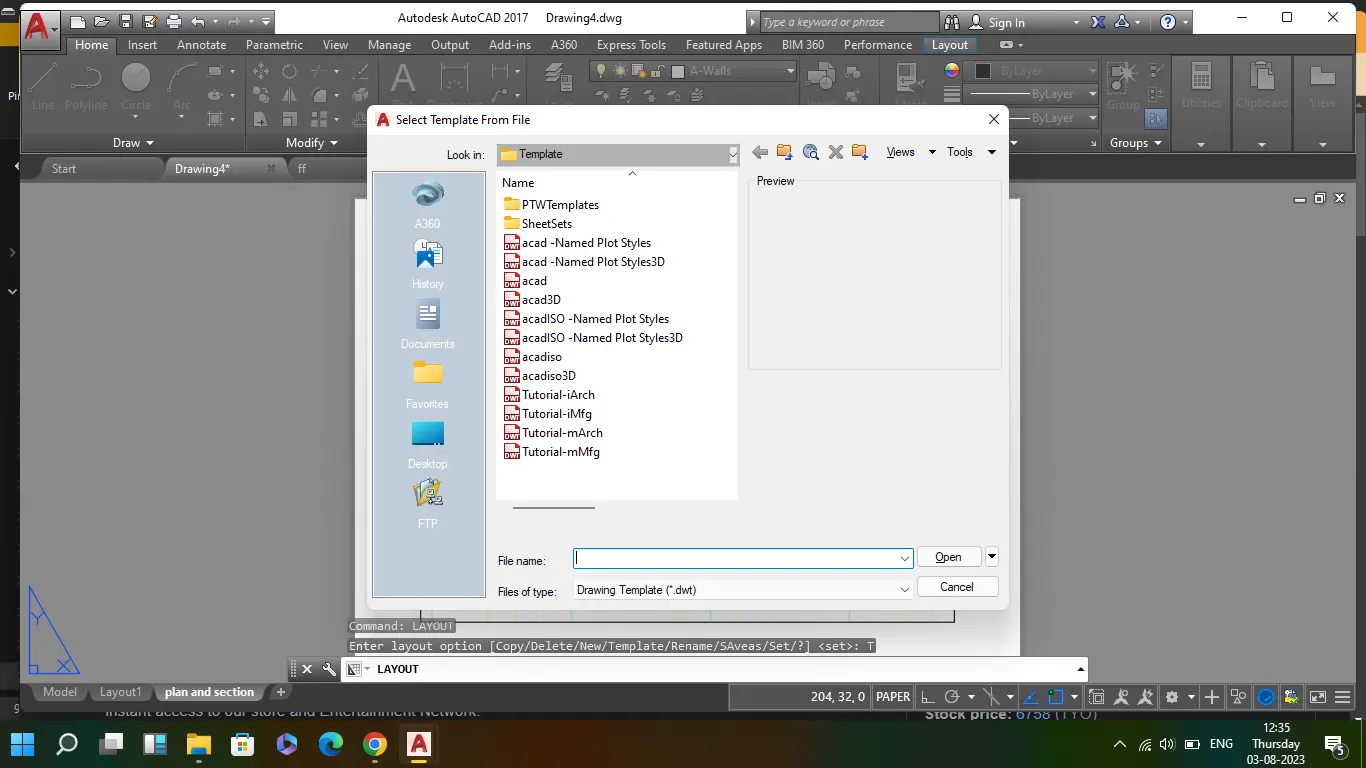
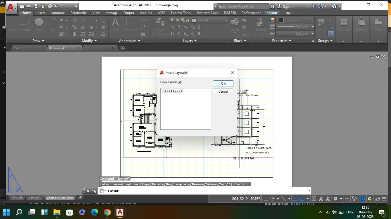
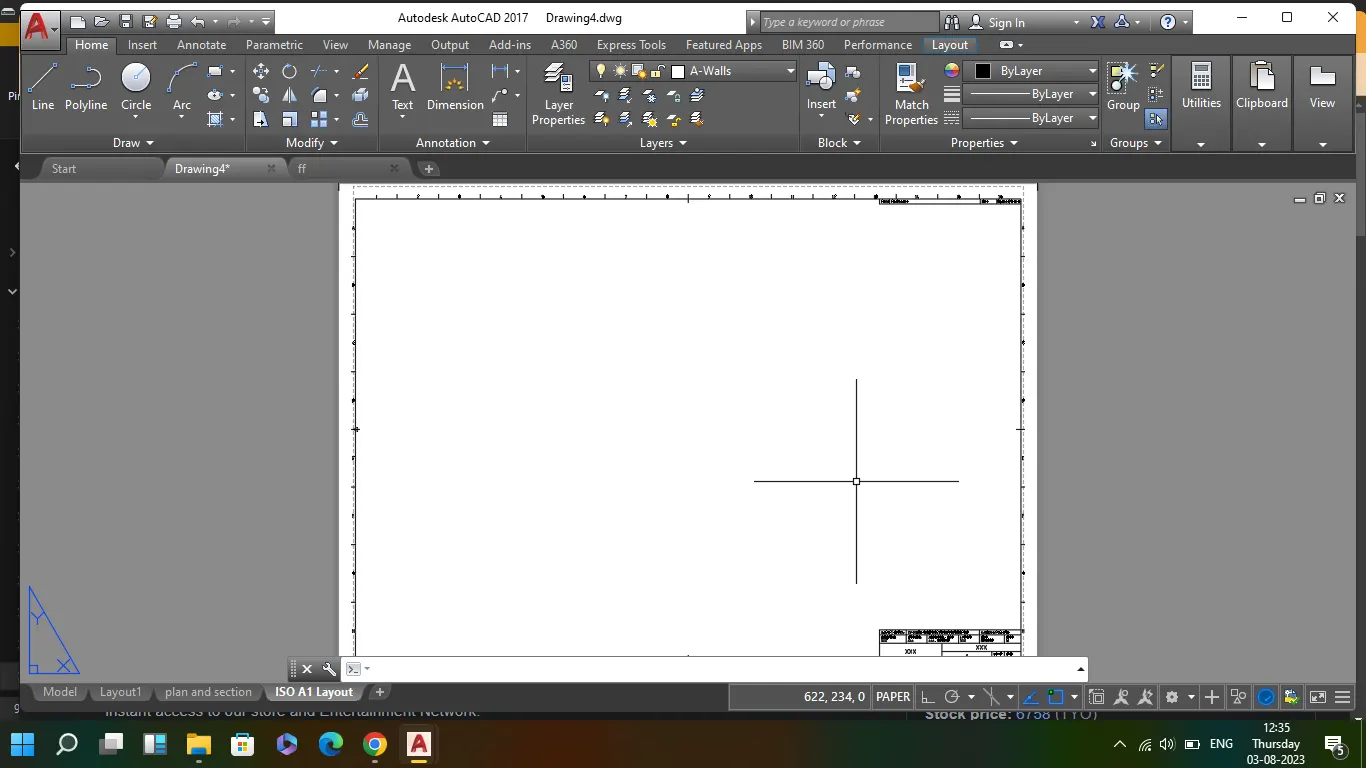
- delete present viewport and add new template called tutorial-mArch.dwt and select ISO A1
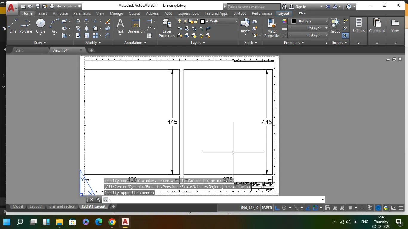
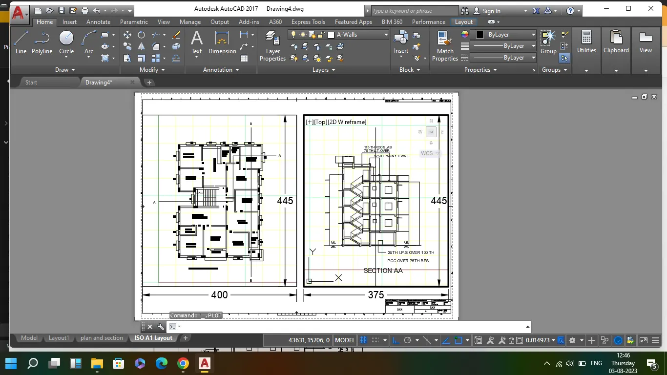
- draw two rect of size 400x445mm and 375x445mm
- using MV command insert the drawing inside the rect and give scale of 1:50 for both using pan adjust the modelspace dwg
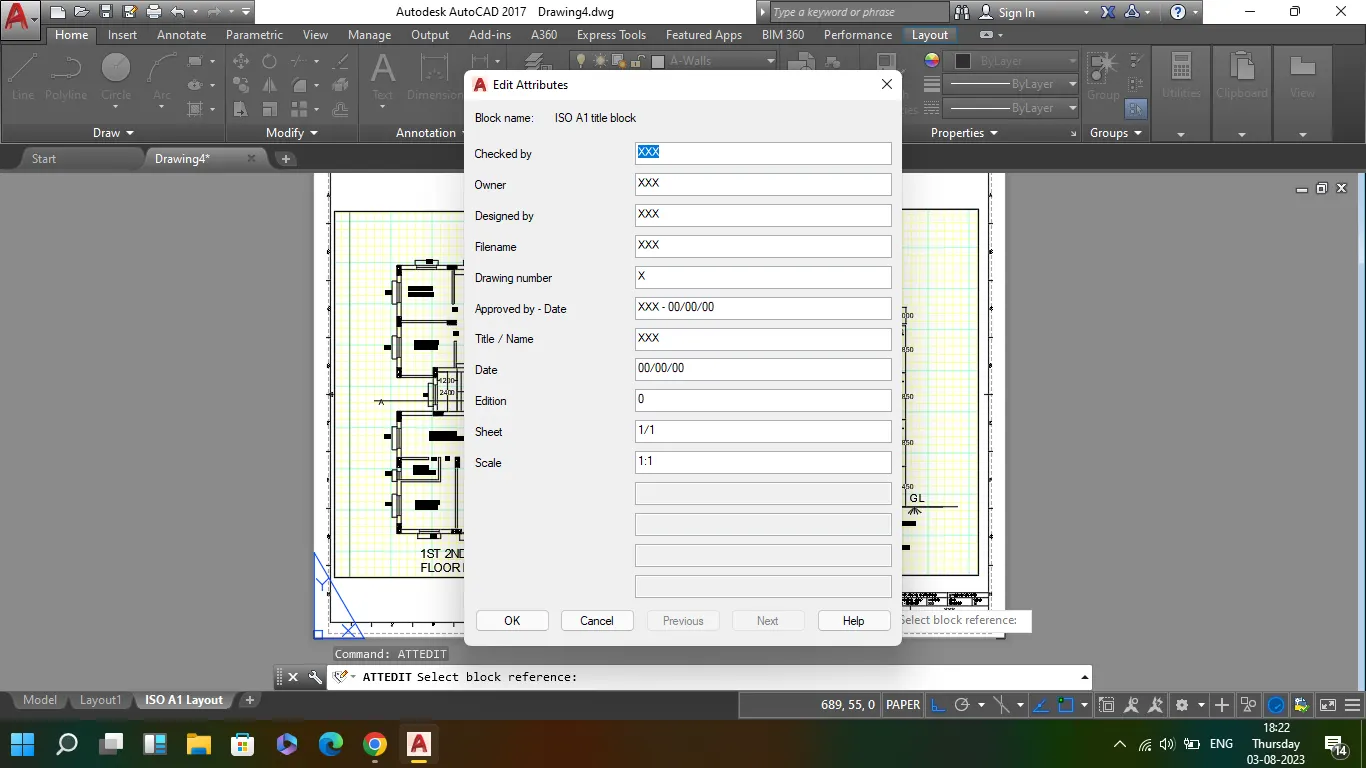
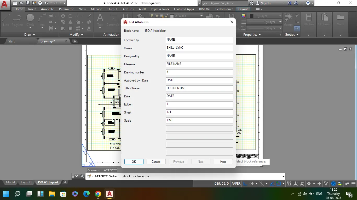
- seclect the block template and give command block edit (ATTEDIT) and give respective names for respective boxes
- using dimlinear give measurments for both the rectangle
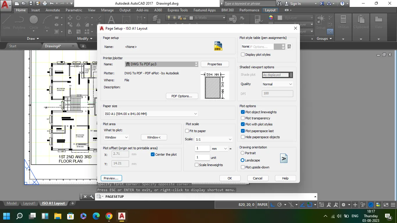
- plot the drawing and take all the respective screenshots and paste here
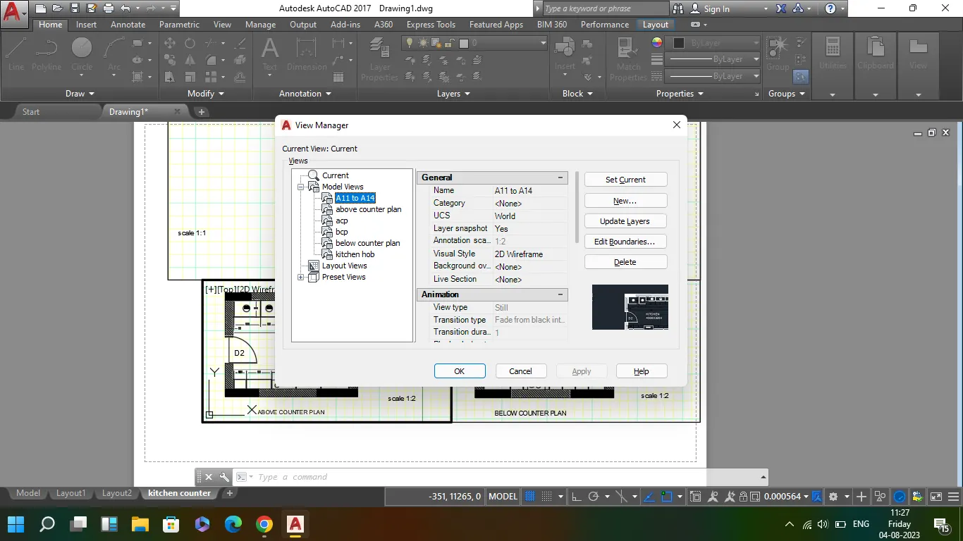
Openthe challenge 9 of kitchen counter and create the layout of kitchen counter with respective scale given using required commands
- open challenge 9 and create the new layout, name it as kitchen counters
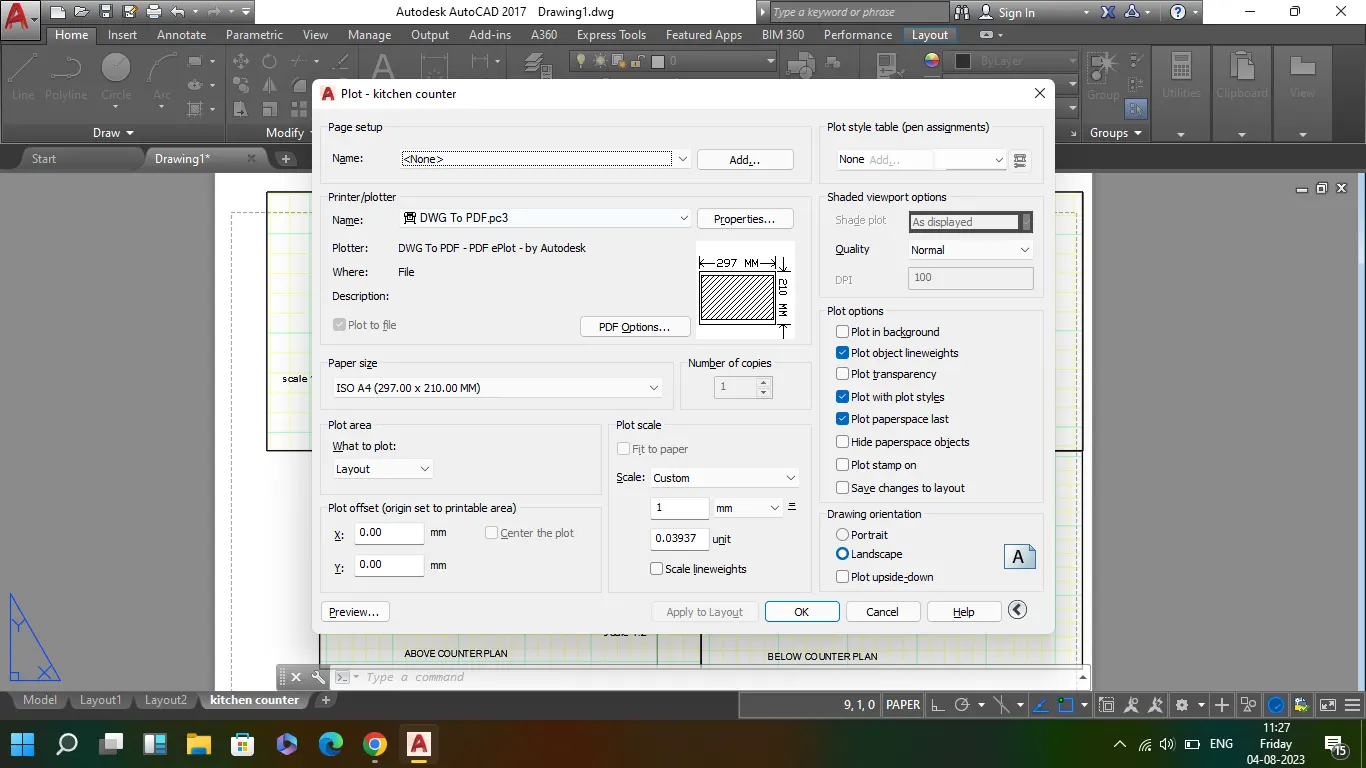
- open page setup manager and select A4 sheet and press ok
- go to model and using view command create 4 dwg respectively according to its scale and as per given in challaenge
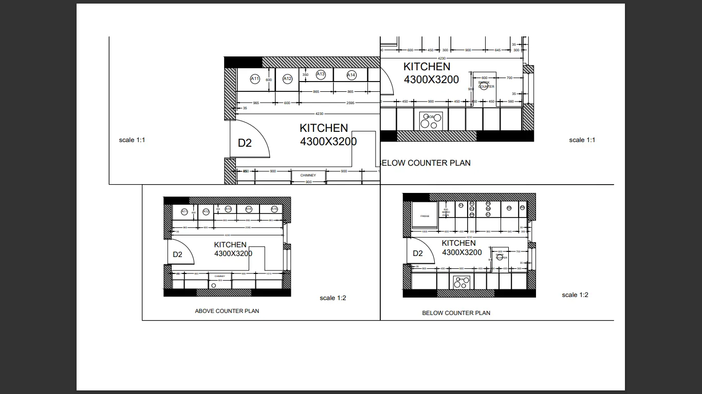
- divide the layout page into 4 parts using rect and insert dwg in each using MV
- by using model space and view command place the respective dwg in each rect and scale it accordingly
- use paper space command and use DT to enter scale text to each parts
- plot the respective dwg in A4 sheet and save it in pdf format
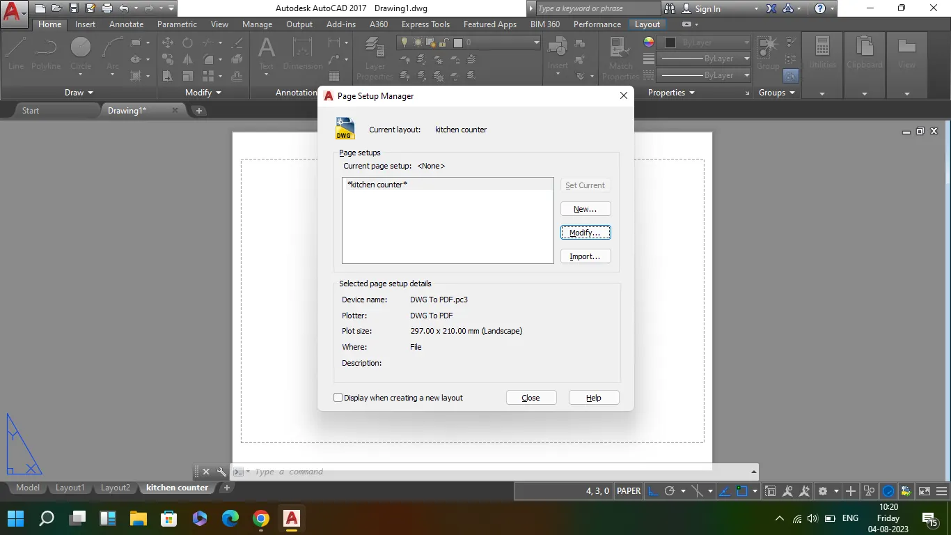
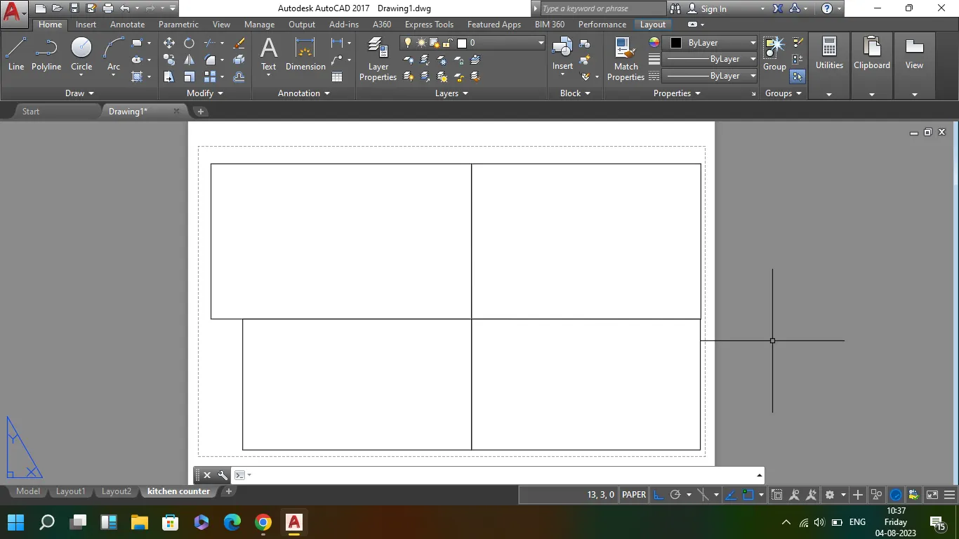
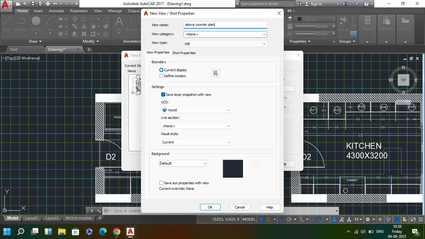
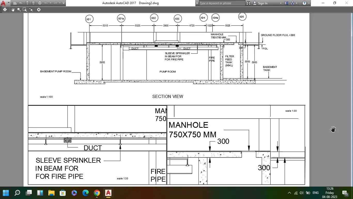
Open the challenge 9 pump room and create a layout using respective commands as VIEW, MV,PAGE SETUP MANAGER, MODELSPACE, PAPERSPACE AND TEXT
- open challenge 9 pump room and create new layout
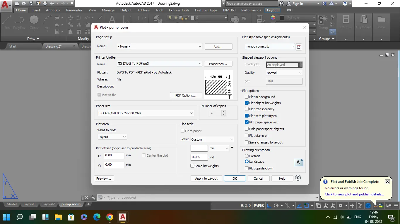
- open page setup manager and select A3 sheet and divide it into 3 parts as given in challange
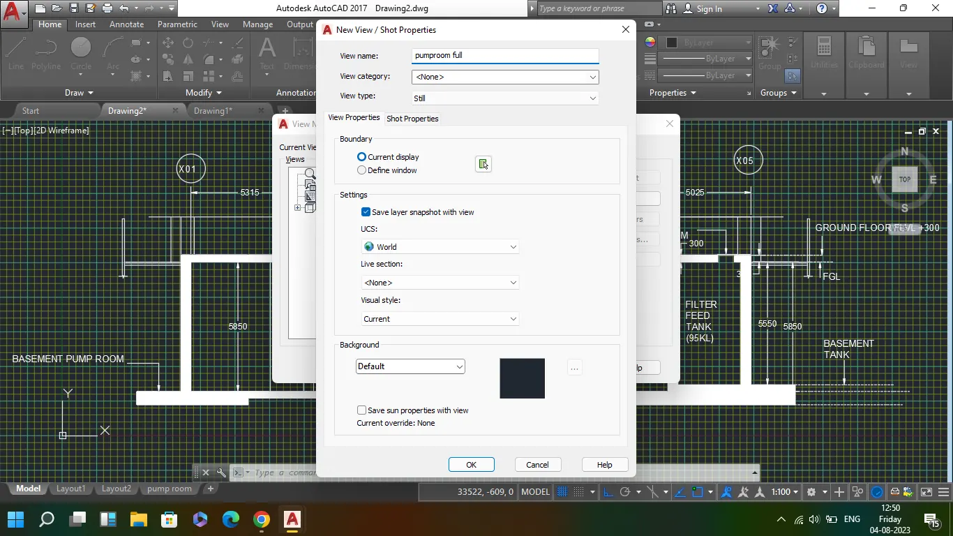
- go to model, here using view command create 3 view files of whole pump room, duct and sprinkler and man hole
- come to layout in respective 3 parts place dwg using MV command
- go to each part using MS command and using V command place all the dwg in layout
- give required scale and using pan adjust the dwg in layout and using PS comeout of MS , here in PS using DT place text of scale in each parts
- plot the layout convert it into pdf and press ok