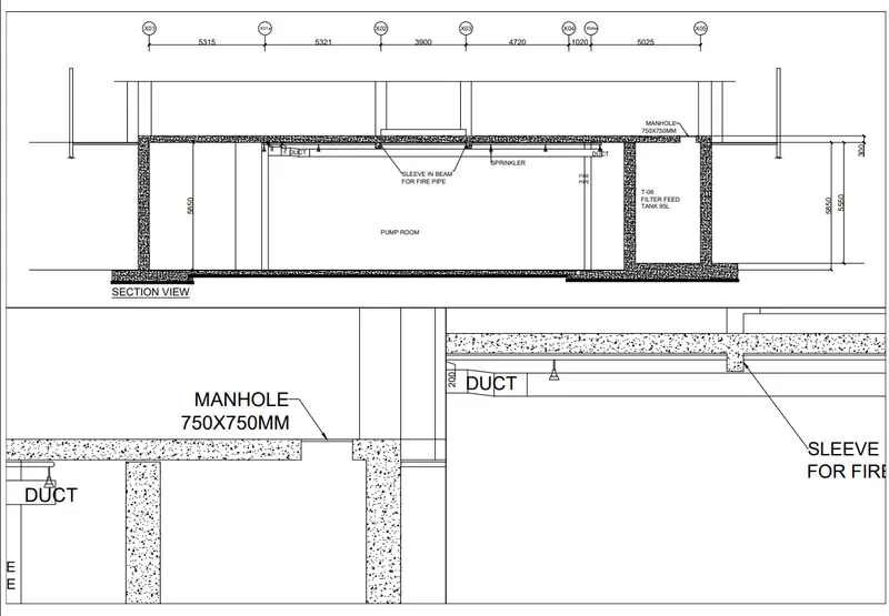
Creation of Multiple viewports, Scaling the drawing and setting in Template in AutoCad
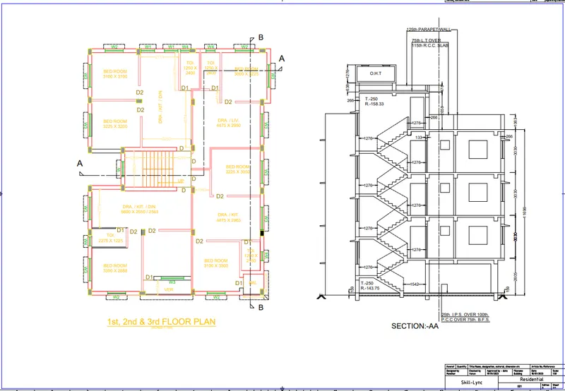
1. Create a layout of the Plan and Section A of the project in Challenges 7, using the template Tutorial-mArch.dwt in a scale as given in the Figure. Use the MV command to create the viewport of the size as shown in Figure. Also, use the ATTEDIT command to edit the information in the title block. Use A1 size for the layout. Take a plot.
AIM:
To create a layout of the Plan and Section A of the project in Challenges 7.
REQUIRED TOOLS:
NAMED VIEWS
MODEL VIEWPORTS
LAYOUT
MULTIVIEW
MODEL SPACE
SCALE
PAN
PAPER SPACE
DTEXT
DISTANCE
EDIT ATTRIBUTE
ANNOMONITOR
PROCEDURE:
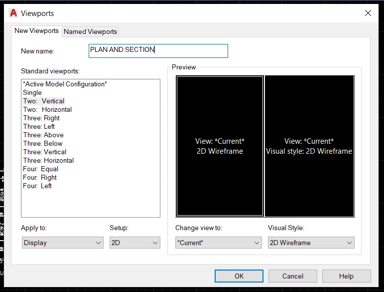
MODEL VIEWPORTS:
Creating the VIEW PORTS in the Model, for working on the different viewports.
Invoking the Tool:
RIBBON: VIEW>MODEL VIEWPORTS>NAMED>NEW VIEWPORTS
For changing the viewports in different ways just use the VIEW CONFIGURATION in model viewports.
NAMED VIEWS:
Creating the Named Views:
When we are working on a bunch of drawings, at the time of finding the particular drawing the Named views tool is useful.
Invoking the Tool:
RIBBON: VIEW>NAMED VIEWS>NEW VIEW>
Select the View Tab on the Ribbon and select the New view in the Named View tool pallet and create the New View.
LAYOUT:
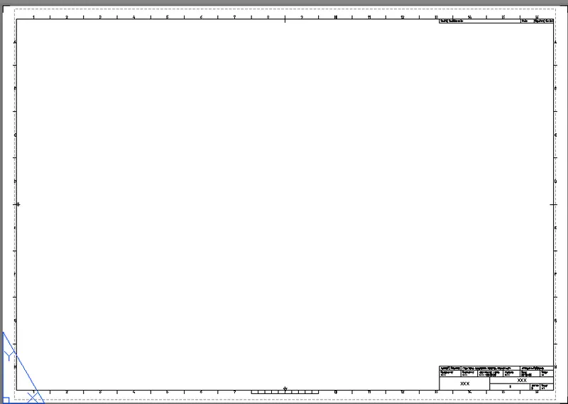
Creating the Layout along with the TEMPLATE.
The template shows the details of the project, Schedules, and Outlines Specifications about the project.
Invoking the Tool:
COMMAND: LAYOUT> TEMPLATE> mArch>
Type on Command as Layout and select the Template as given in the options and select the Tutorial-mArch then open in the new layout.
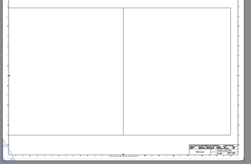
Creating the rectangles with a given dimension on the Layout.
Invoking The Tool:
Command: REC>
Select the first corner point and give the dimension in X-axis 400 and Y-axis 445, and create another rectangle with a dimension of 375X445 like as shown in the below-given drawing.
MULTIVIEW:
MultiView is used for creating the view on the layout, for creating the view type MV on the command and selecting the View portion by taking the two corner points of the first rectangle on the layout.
Set the drawing by using the Named View Tool as earlier saved the view just insert by choosing the named view.
Invoking the Tool:
COMMAND: MV>
MODEL SPACE:
Model Space is used for adjusting and working the drawing in the Layout
Invoking the Tool:
COMMAND: MS>
SCALE:
Set the scale to fit the drawing in the layout.
PAN:
After setting the scale to the drawing adjust the object by using the PAN command, don't use the zoom command for setting the object it will change the scale and set it as a different scale.
PAPER SPACE:
Paper space is used for zooming the paper.
Invoking the Tool:
COMMAND: PS>
DTEXT:
For writing the text in the Layout Set the layout as in the Paper space mode, and type DT in the command and specify height as we required, and write the data.
Invoking the tool:
Command: DT>
DISTANCE:
It is used for measuring the distances of the object, the distance command is working on the Paper Space mode only.
Invoking the tool:
COMMAND: DI>
EDIT ATTRIBUTE:
For Editing the Template on the layout the Attribute Edit command is used on the Paper Space mode.
Invoking the Tool:
COMMAND: ATTEDIT>
Edit the attribute as per our data and press OK>
DIMENSIONS:
COMMAND: DIMLIN>
Plot the dimension to the inserted drawing box.
ANNOMONITOR:
After Plotting the dimension the yellow color badge will be displayed for non-associative dimensions and leaders, for switching Off to them use the Annomonitor Command.
Invoking the Tool:
COMMAND: ANNOMONITOR>
RESULT:
Plot the Layout of the Plan and Section by using the Various commands and tools.
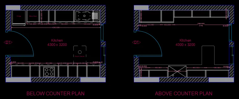
2. Create a layout of the Kitchen drawn in Challenge 9 as shown in Figure. Use the scale as shown in the Figure. Use the A4 Size page for the layout. Take a plot.
AIM:
Create a layout of the Kitchen drawn in Challenge 9 as shown in Figure.
REQUIRED TOOLS:
NAMED VIEWS
MODEL VIEWPORTS
LAYOUT
MULTIVIEW
MODEL SPACE
SCALE
PAN
PAPER SPACE
DTEXT
PROCEDURE:
MODEL VIEWPORTS:
Creating the VIEW PORTS in the Model, for working on the different viewports.
Invoking the Tool:
RIBBON: VIEW>MODEL VIEWPORTS>NAMED>NEW VIEWPORTS
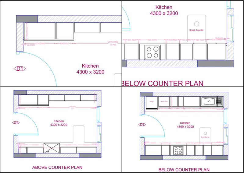
For changing the viewports in different ways just use the VIEW CONFIGURATION in model viewports, select the Four equal parts of view configuration.
NAMED VIEWS:
Creating the Named Views:
Invoking the Tool:
RIBBON: VIEW>NAMED VIEWS>NEW VIEW>
Select the View Tab on the Ribbon and select the New view in the Named View tool pallet and create the New View as given below.
Creating the Four Named View as shown in the given drawing.
LAYOUT:
Creating the Layout without Template.
Invoking the Tool:
COMMAND: LAYOUT> NEW>
Type on Command as Layout and select the NEW option and Name the Layout whichever creates.
PAGE SETUP:
Place the Curser on the layout and right-click the mouse, then select the Page setup Manager and give the data as we required.
Printer/Plotter:
Name: For converting the Drawing file to PDF select the DWG To PDF.pc3 option in the list.
Paper size:
Select the ISO A4 size paper.
Plot area:
choose the layout option because now we are working on the layout page.
Scale:
Select the 1:1 for plotting the same size as the paper.
Plot style table:
For the drawing object plotting into black and white choose the monochrome.ctb option from the list.
PAPER SPACE:
Paper space is used for zooming the paper.
Invoking the Tool:
COMMAND: PS>
MULTIVIEW:
MultiView is used for creating the view on the layout, for creating the view type MV on the command, and plot on the layout as shown in the figure.
Set the drawing by using the Named View Tool as earlier saved the view just insert by choosing the named view.
Invoking the Tool:
COMMAND: MV>
MODEL SPACE:
Model Space is used for adjusting and working the drawing in the Layout
Invoking the Tool:
COMMAND: MS>
SCALE:
Set the scale to fit the drawing in the layout.
Scale is chosen 1:30 and 1:50 as fit to the page in Layout.
PAN:
After setting the scale to the drawing adjust the object by using the PAN command.
Invoking the tool:
COMMAND: PAN>
DTEXT:
Invoking the tool:
COMMAND: DT>
For creating the text on the layout using the DT command.
RESULT:
Sketching the Layout by using the various command and tools.
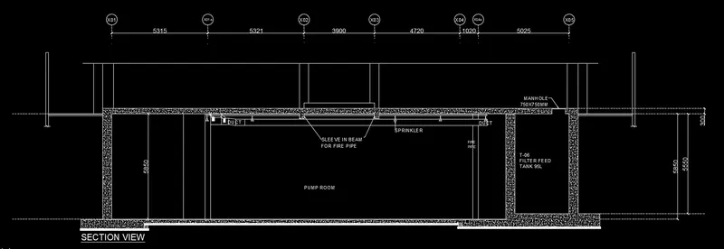
3. Create a layout of the section created in Challenges 9.
Use the scale as mentioned in the Figure. Use the MV command to create multiple viewports. Take a plot.
AIM:
To create a layout of the section created in Challenges 9.
REQUIRED TOOLS:
MODEL VIEWPORTS
NAMED VIEWS
LAYOUT
MULTIVIEW
MODEL SPACE
SCALE
PAN
PAPER SPACE
DTEXT
PROCEDURE:
MODEL VIEWPORTS:
Creating the VIEW PORTS in the Model, for working on the different viewports.
Invoking the Tool:
RIBBON: VIEW>MODEL VIEWPORTS>NAMED>NEW VIEWPORTS
Select the Three-Above option in the list of View Configuration.
NAMED VIEWS:
Creating the Named Views:
Invoking the Tool:
RIBBON: VIEW>NAMED VIEWS>NEW VIEW>
Select the View Tab on the Ribbon and select the New view in the Named View tool pallet and create the New View as given below as section view, Manhole, Sleeve sprinkler.
PAGE SETUP:
Place the Curser on the layout and right-click the mouse, then select the Page setup Manager and give the data as we required.
Printer/Plotter:
Name: For converting the Drawing file to PDF select the DWG To PDF.pc3 option in the list.
Paper size:
Select the ISO A3 size paper.
Plot area:
choose the layout option
Scale:
Select the 1:1 for plotting the same size as the paper.
Plot style table:
For the drawing object plotting into black and white choose the monochrome.ctb option from the list.
Plot options:
Choose the options as per requirements.
Drawing Orientation:
Choose the Landscape Option and Press OK>
PAPER SPACE:
Paper space for zooming and adjusting the paper
Invoking the Tool:
COMMAND: PS>
MULTIVIEW:
MultiView is used for creating the view on the layout, for creating the view type MV on the command, and plot on the layout as shown in the figure.
Set the drawing by using the Named View Tool as earlier saved the view just insert by choosing the named view.
Invoking the Tool:
COMMAND: MV>
MODEL SPACE:
Model Space is used for adjusting and working the drawing in the Layout
Invoking the Tool:
COMMAND: MS>
SCALE:
Set the scale to fit the drawing in the layout.
Scale is taken 1:100 and 1:30 as fit to the page in Layout.
PAN:
After setting the scale to the drawing adjust the object by using the PAN command.
Invoking the tool:
COMMAND: PAN>
DTEXT:
Invoking the tool:
COMMAND: DT>
For creating the text on the layout using the DT command.
RESULT:
Creating the LAYOUT of the given drawing by using various commands and tools.