Creation of Multiple viewports, Scaling the drawing and setting in Template in AutoCad
AIM:-
- To Create a layout of the Plan and Section A of the project in Challenges 7, using the template Tutorial-mArch.dwt in a scale as given in the Figure. Use the MV command to create the viewport of the size as shown in Figure. Also, use ATTEDIT command to edit the information in the title block. Use A1 size for the layout. Take a plot.
- To Create a layout of the Kitchen drawn in Challenge 9 as shown in Figure. Use the scale as shown in the Figure. Use A4 Size page for the layout. Take a plot.
- To Create a layout of the section created in Challenges 9. Use scale as mentioned in the Figure. Use MV command create multiple viewports. Take a plot.
INTRODUCTION:-
- A drawing template file is a drawing file that has been saved with a . dwt file extension, and it specifies the styles, settings, and layouts in a drawing, including title blocks. The default drawing template files are provided as samples.
- Efficiency is also gained through template files because there is no need to set up your file. Apart from titleblocks, a good template will also contain page setups. A page setup is made up of the settings needed for a drawing to be properly printed from AutoCAD.
COMMANDS USED:-
- Viewport
- Layout
- Multiple View
- Model Space
- Paper Space
- Scale
- Xref
- Lock
- Pan
- Plot
Those are briefly elborated below:-
VIEWPORT:- Viewports allow you to create different views of the objects in your model space and display them on the printed page from different angles and at different scales.
LAYOUT:- A layout is a 2D working environment for creating drawing sheets. The area within a layout is called paper space, where you can add a title block, display scaled views of model space within layout viewports, and create tables, schedules, notes, and dimensions for your drawing.
MULTIPLE VIEW:- Use the command "MV" multiple view- select object option and click on the rectangle, then the drawing will be displayed in the viewport. Similarly do it for the second rectangle. Command "MS" for model space and click on the viewport we need to set the drawing.
MODLE SPACE:- When you start a drawing session, your initial working area is called model space. Model space is an area in which you create two-dimensional and three-dimensional entities based on either the World Coordinate System (WCS) or a user coordinate system (UCS). You view and work in model space while using the Model tab.
PAPER SPACE:- In the layout viewports, you scale the model space views relative to paper space. One unit in paper space represents the actual distance on a sheet of paper, either in millimeters or inches, depending on how you configure your page setup.
SCALE:- Enlarges or reduces selected objects, keeping the proportions of the object the same after scaling. To scale an object, specify a base point and a scale factor.
XREFS:- In AutoCAD, xref is a shortened term for “external references”. As the name indicates, the xref feature allows you to attach external references to your drawing. External references can be in the format of other drawings, PDFs, images, point cloud data, and so on.
LOCK:- To create a layout viewport that fills the screen, choose Fit. To lock the viewport scale and view in model space when panning or zooming in the layout viewport, choose Lock.
PAN:- Pan: Hold down the mouse wheel as you move the mouse around your drawing. Zoom in: Roll the mouse wheel forward (i.e., toward your computer). Zoom out: Roll the mouse wheel backward (i.e., toward you).
PLOT:- From the Ribbon Output tab > Plot panel, click the Plot button. Command line: To start the Plot tool from the command line, type “PLOT” and press [Enter]. From the Page Setup list, select your newly created page setup and click OK to plot using the selected settings.
AIM_1:-
- To create layout of plan and section using Template mArch.dwt.
- To create viewport using MV command of size 400x445 and 375x445 and setting the scale (1:50)
- Editing Attributes in the template.Take a plot using A1 size.
PROCEDURE:-
- In the command prompt type units > mm> decimal
- In the command prompt type limax >10000,10000
- In the command prompt type limits>0,0
- Save the dwg file as Challenge10_1 and then use command "XREF" in command prompt and on the left corner attach the Dwg.Attach the drawing.
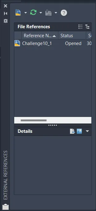
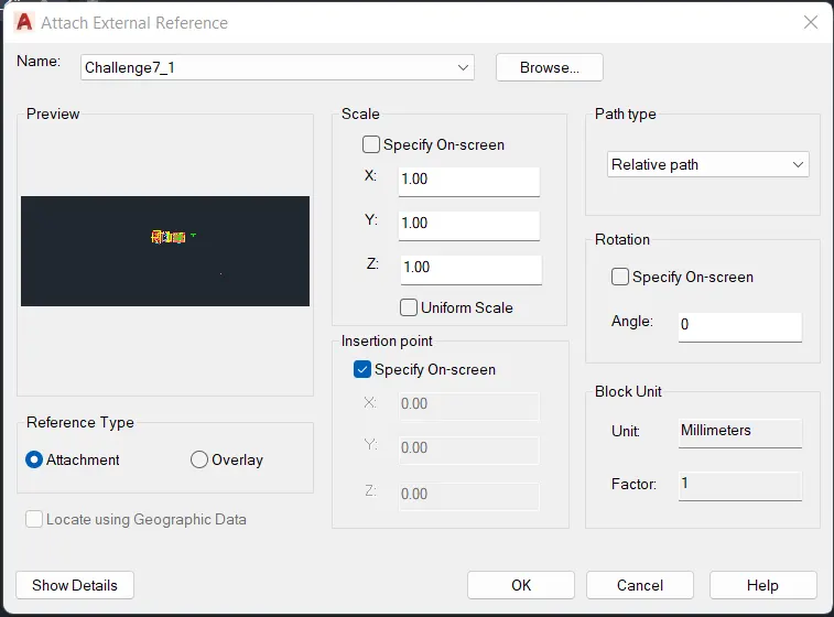
- Open dwg file from external reference file tab. That is open Challenge7_1 in which reference type opted is attachment.
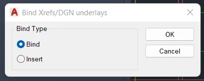
- Bind the attached file and then explode the drawing file to work on it.
- Click on the layout tab right click it and create a new layout. Rename the layout tab as plan and section. Delete the current viewport displayed in the layout.
- To create the template, use command "LAYOUT" select template(.dwt) - select "mArch." from the dialogue box, select ISO A1 layout and re name it as Layout of Plan and Section.
- Type “MS" for the activation of model space.
- To create viewport, draw a rectangle of size 400x455 and 375x445 for creating the viewport.
- By using dimlinear command set the dimension as shown in the figure.
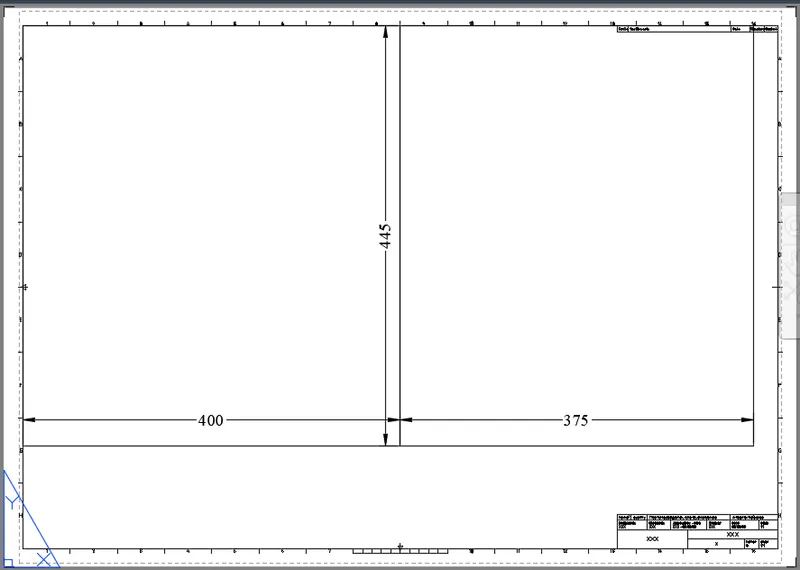
- Use the command "MV" multiple view- select object option and click on the rectangle, then the drawing will be displayed in the viewport. Similarly do it for the second rectangle.
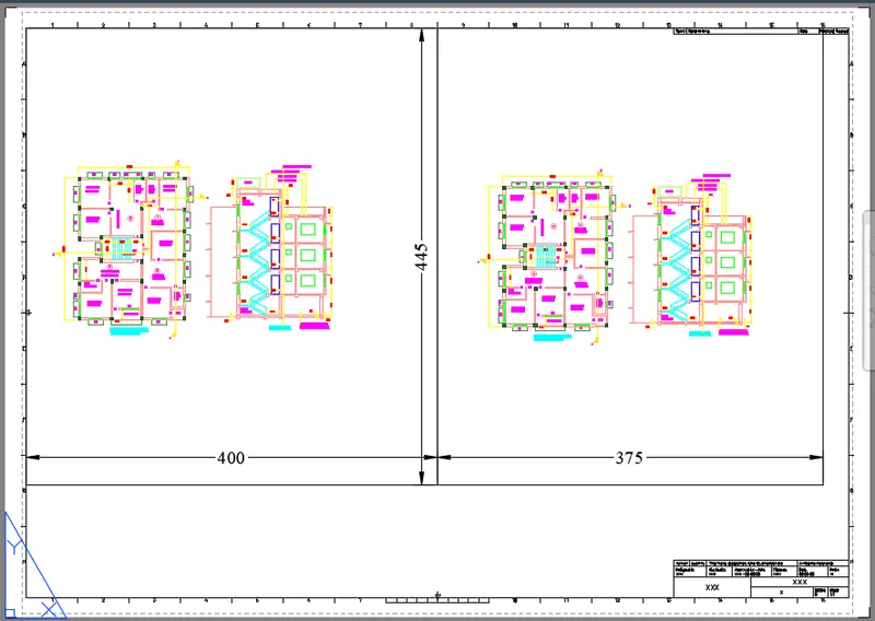
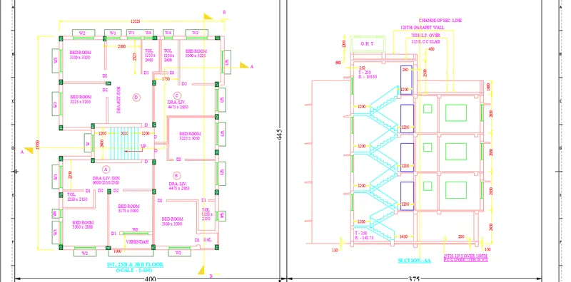
- Command "MS" for model space and click on the viewport we need to set the drawing. Click on the first viewport and zoom in the drawing for the plan and give a scale of 1:50 and lock the viewport so that further zooming will not change the scale.
- Similarly do it in second viewport zoom in the section view, making it a scale of 1:50 and lock.
- Now to edit the attribute in template, Go to paper space by command “PS" and click on the template which is a block. Click on the attributes and edit the attributes- double click the attribute text or command "ATTEDIT”, the attribute dialogue box appears.
- Give the value as NAME, DATE, scale etc.
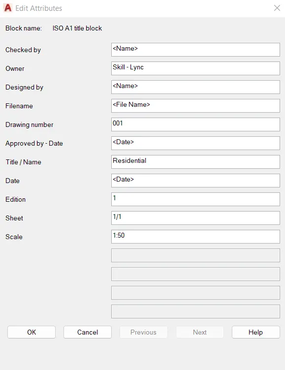
- Click ok tab and then check the template wheather it is changed as per requirement.
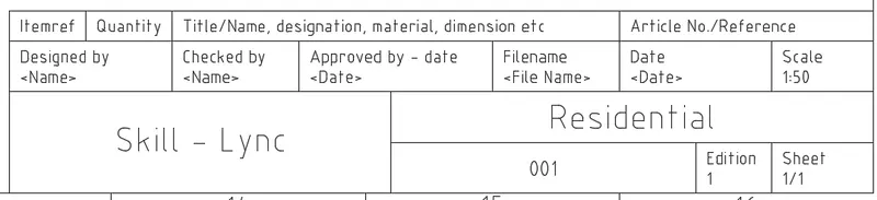
- Enter the text by multiline text in paper space and with text height 20 and write the text as Scale 1:50.
- And then take the Plot using A1 sheet.
- Use command "PLOT”, the dialogue box appears.Give the name as "DWG to PDF".Select the paper size as ISO A1 (594x841 mm).
- Select what to plot as layout.Scale is given as 1:1, orientation is given as landscape.Select the pen assignment as "Monochrome" so that the print will be in lack.
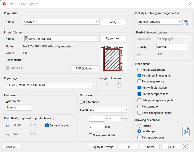
- Preview the plot before saving it as a reference pdf file.
RESULT:-
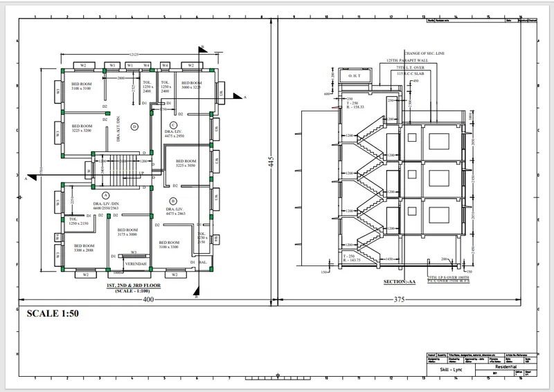
Layout is created using template m.Arch.dwt.Viewport is created using MV command of size 400x445 and 375x445mm and the scale of viewport is set to 1:50. Attributes in the template are edited.A plot is taken using A1 size.
_________________________________________________________________________________
AIM_2:-
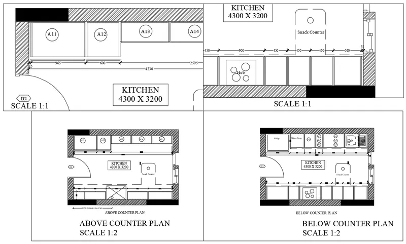
To take different view of kitchen for layout in model space,create the layout with four viewports, with A4 sheet,create a plot.
PROCEDURE:-
- In the command prompt type units > mm> decimal
- In the command prompt type limax >10000,10000
- In the command prompt type limits>0,0
- Save the dwg file as Challenge10_2 and then use command "XREF" in command prompt and on the left corner attach the Dwg.Attach the drawing.
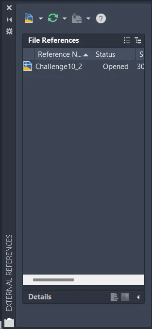
- Open dwg file from external reference file tab. That is open Challenge9_1 in which reference type opted is attachment.
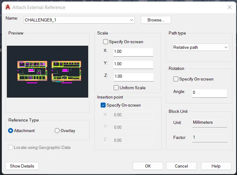
- Bind the attached file and then explode the drawing file to work on it.
- Take different views for the layout in model space.Open the drawing, use command "VIEW" to create new views. The view manager dialogue box appears. Click on model, click on new to create new view.
- Another dialogue box of new view appears, give the view name as "Above Counter Plan" select the boundary as define window, and select it using the window selection from the drawing.
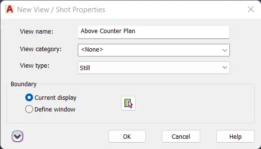
- Click on OK and the view with name above counter plan and the selected drawing will be created.Similarly create views for below counter plan, hob and A11 to A14 cabinets.
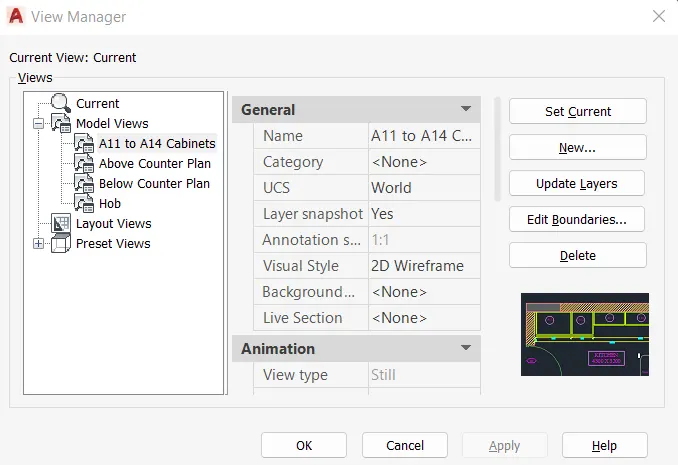
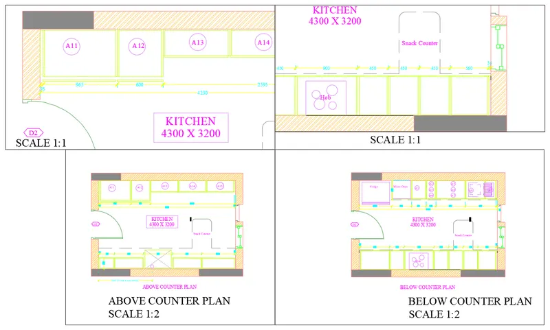
- Select the A11 to A14 cabinet view in the first viewport, zoom and pan to fit in the viewport
- Create the layout with four viewports, with A4 sheet.Open the layout tab, rename the layout as kitchen layout.Delete the existing viewport.
- Default is the A4 sheet.
- With "MV" command create 4 viewports by making the window.
- Type command "VIEW" in the layout tab, select the required view and click on the viewport where it has to be displayed and lock each viewport.
- Select the A11 to A14 cabinet view in the first viewport, zoom and pan to fit in the viewport.
- Go to paper space, with Text command type SCALE 1:1.
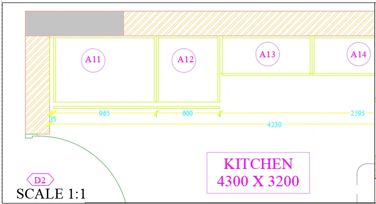
- Enter command "MS" click on the second viewport.Enter the command "VIEW" and select the view name snack counter.
- Zoom and pan the viewport to make the view fit in the viewport.Lock the viewport.Go to paper space and with command "T" enter the text SCALE 1:1.
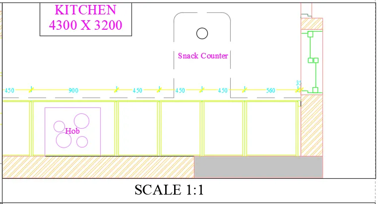
- Similarly in model space click on third viewport.Enter the view above counter plan.Zoom and pan the viewport, so that the drawing fit in it.
- Lock the viewport. Go to paper space and with command "T" enter the text as ABOVE COUNTER PLAN and SCALE 1:2 with text height 3.5.
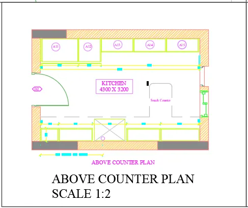
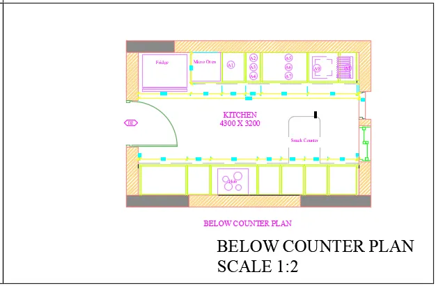
- Similary in model space click on third viewport.Enter the view below counter plan.Zoom and pan the viewport, so that the drawing fit in it.
- Similary in model space click on third viewport.Enter the view below counter plan.Zoom and pan the viewport, so that the drawing fit in it.
- All viwes are locked and then shown together below.
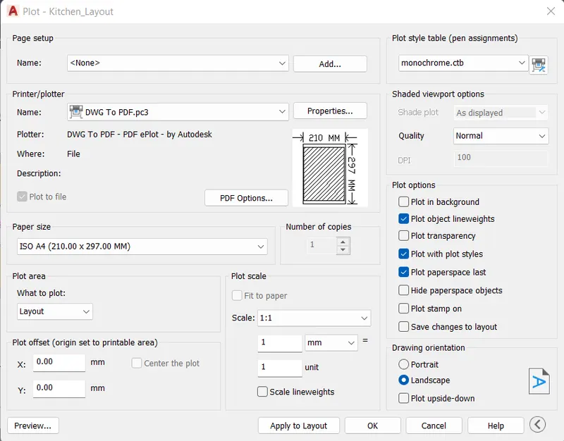
- Create a plot, Use "PLOT" command, plot dialogue box appears.Paper size is selected as A4 and name is given as A4, printer name ad print to pdf.
- Select what to plot as layout, and select pen assignment as monochrome. Preview the print.Select ok to convert to pdf.
RESULT:-
Different view of kitchen for layout in model space is created ,layout with four viewports, with A4 sheet is created,a plot is created.
_________________________________________________________________________________
AIM_3:-
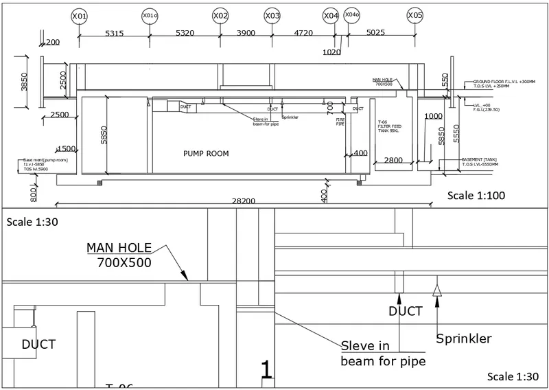
Create layout of the section of industrial building ,creating viewport by MV command (Multiview port) and scale 1:30 and 1:100 is given,to take a plot of the layout.
PROCEDURE:-
- In this challenge, I have opted to work on the existing sheet that is Challenge_9. In which I haven't created any layers.
- I have created the figure as given and then appilied layers.
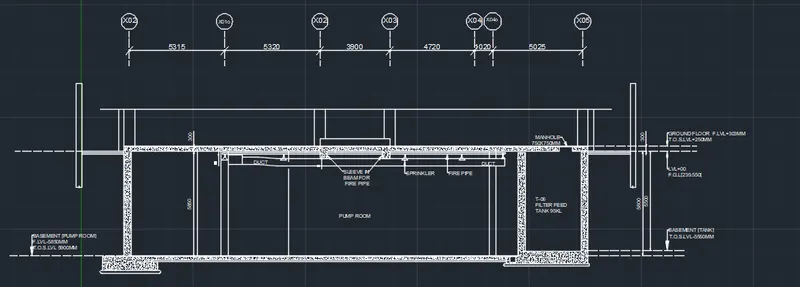
- Now, in the command prompt type V to create the model view of the section.
- Then provide the view name and choose the boundary option.
- Click on model view and then click New button.
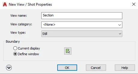
- Now, click ok. Then another Tab is displayed that is view manager.
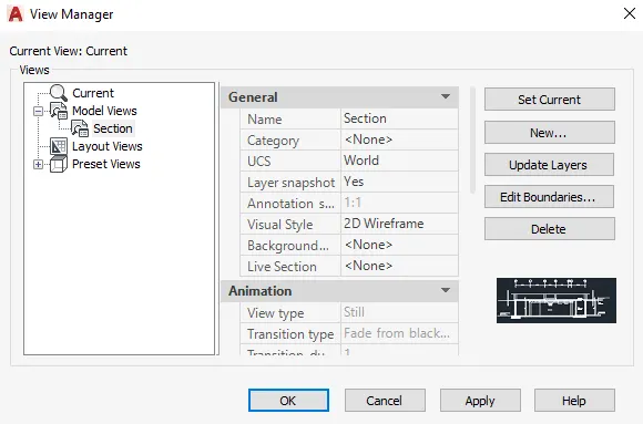
- Again click on ok.
- Hence, model view is created.
- Now, go to layout option and select new and type the name of the layout as Section.
- For creating the Industrial Building Layout. Take the layout tab and Rename the tab as industrial section.
- Right click on the tab and select page set up manager option.Click on new - give a name, page setup dialogue box appears.
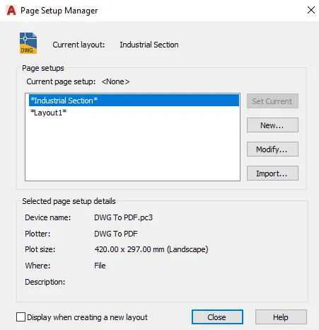
- Click on Modify.Give the paper size as A3 in page setup dialogue box. Make it current, the layout paper size changes to A3.
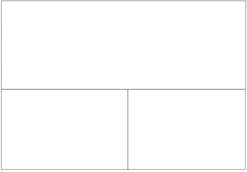
- Use "MV" command and create 3 viewports accordingly.
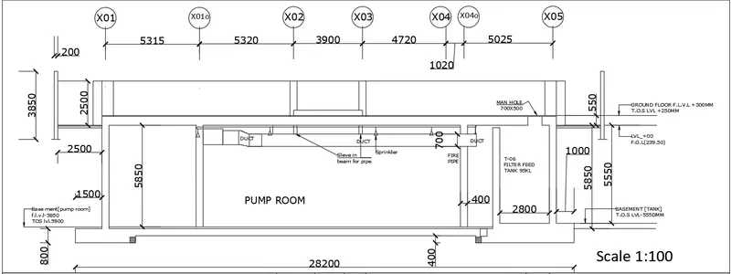
- Use Command "MS" for the model space, click on the first viewport .Set the scale to 1:100 from the bottom toolbar or right click and properties, from there also we can change the scale.
- By pan command fit the drawing inside the viewport.By text command write the text as SCALE1:100 with a text height of 6 and lock the viewport.
- Again, Go to model view, and create views for the next two viewports.
- Command "VIEW" -view manager dialogue box appears -create new-give name as manhole view -select define window and select the view we need to create, press enter. Similarly create view for sprinkler named as sprinkler view.
- Now go to the layout industrial section and command "MS " and click on the left model space.
- Now use command "view" -select the manhole view- and click on set current.
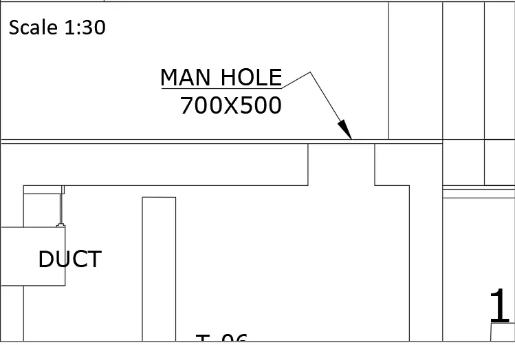
- Then the view will be displayed on the model spaceSelect the scale to 1:30 from the bottom toolbar.
- By multiline text give the text as SCALE 1:30 with a text height of 6.Lock the viewport from the bottom toolbar lock symbol.
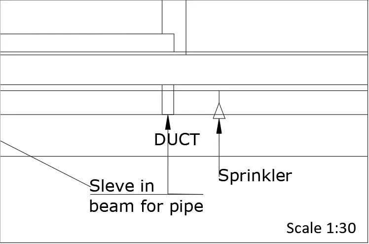
- Type "MS" and click on the third viewport.Use command "VIEW" and select the sprinkler view and make it current.
- Select the scale to 1:30 from the bottom toolbar .By multiline text insert the text as SCALE1: 30 with a text height of 6.Lock the viewport.
-
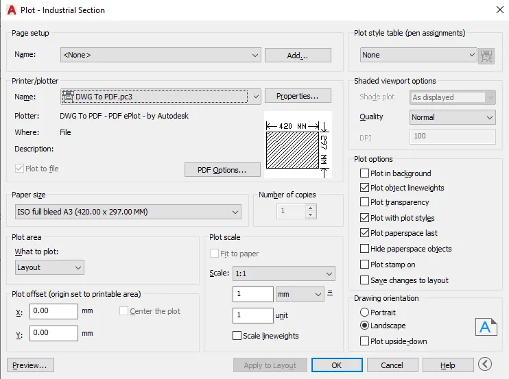
Take a plot of the viewport.Enter the command "PLOT".The dialogue box appears, select paper size as A3, what to plot as layout .Give pen assignments as monochrome.
RESULT:-
Layout of the section of industrial building is created,viewport is created by MV command and scale 1:30 and 1:100 is given. Plot of the layout is taken.
OVERALL RESULT:-
- Layout of the Plan and Section A of the project in Challenges 7, using the template Tutorial-mArch.dwt in a scale as given in the Figure is made. MV command is used to create the viewport of the size. Also, used Attribute edit command (ATTEDIT) to edit the information in the title block and to convert the layout to pdf as mentioned A1 size paper is used for the layout and then made a plot.
- Layout of the Kitchen drawn in Challenge 9 as shown in Figure is made. Scale is used as shown in the Figure. Used A4 Size page for the layout. Made a plot.
- Creation of a layout of the section in Challenges 9 is made. Scale is used as mentioned in the Figure. Used MV command created multiple viewports and then plot is made.