Creation of Multiple viewports, Scaling the drawing and setting in Template in AutoCad
- Aim: To create the layout of the Plan and Section A of the project in Challenges 7, using the template Tutorial-mArch.dwt using AutoCAD software.
Procedure:
- Open the AutoCAD software.
- Go to application menu, select the open option and open the challenge 7 drawing.
- Type Layout in command box, press enter.
- Select template option from command box, select Tutorial-mArch.dwt template, select open, select layout name as ISOA1 layout and select ok.
- Go to the layout from layout tab and right click on it and select page setup manager option.
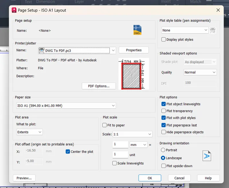
- Select the layout and choose modify option and modify settings from page setup dialog box as shown below and select ok and close.
- Type ATTEDIT in command box and press enter, select the template box and edit the attribute as per required content.
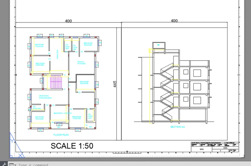
- Type rec in command box, specify the first corner point, select the dimension option from command box, specify the length as 400 and width as 455, press enter, and draw the rectangle.
- Similarly draw the rectangle of size 400 x 455 beside the just drawn rectangle using the rectangle tool.
- In modal space, type V in command box, press enter, select the new option from view manager dialog box, give the name to view as Plan and select define window option and in modal space and define the view of floor plan of challenge 7 using the window.
- Similarly create the view naming Section for section AA by selecting new option from view manager dialog box and select ok.
- Go to layout from layout tab type MV in command box, press enter, select the object option from command box, press enter, select the first rectangle.
- Type MS in command box, press enter, select the first viewport.
- Type V in command box, select the Plan modal view from view manager dialog box, select set current and ok.
- Type PAN in command box, press enter, and adjust the view such that it fit inside the viewport.
- Type PS in command box, select the view port, right click, go to properties option and lock the display.
- Again, type MV in command box, press enter, select the object option from command box, press enter, select the second rectangle.
- Type MS in command box, press enter, select the second rectangular viewport.
- Type V in command box, select the Plan modal view from view manager dialog box, select set current and ok.
- Select the standard scale as 1:50 from scale tab of status bar.
- Type PAN in command box, press enter, and adjust the view.
- Type PS in command box, select the view port, right click, go to properties option and lock the display.
- Type ST in command box, press enter, select the font name arial with the height as 0 units and select ok.
- Type DT in command box, press enter, specify first corner point, type ‘SPACETRANS in command box, press enter, select the viewport, specify rotation angle as 0 and type text as ‘SCALE – 1 : 50’.
- Type DIMLIN in command box, press enter and give dimensions to the rectangles.
- Go to layout tab, right click on layout tab and select the plot option, select continue to plot single sheet, check the settings and select the preview option and see the preview.
- Right click on preview and select the plot option, give the file name and save it in desired folder.
Result: The layout of plan and section of challenge 7 using AutoCAD software by following above mentioned procedure is shown below.
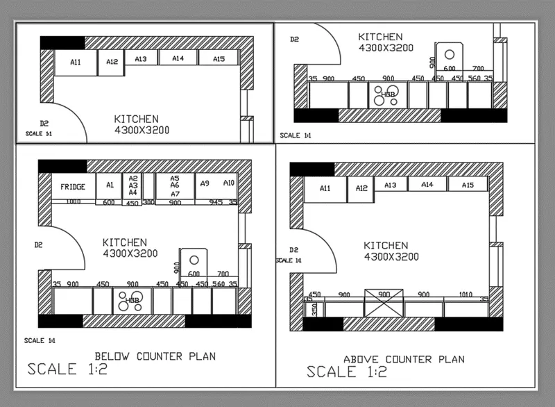
- Aim:To create a layout of the Kitchen drawn in challenge 9 using AutoCAD software.
Procedure:
- Open the AutoCAD software.
- Go to application menu, select the open option and open the kitchen drawing of challenge 9 drawing.
- Go to the layout from layout tab and rename the layout as ‘kitchen layout’.
- Go to layout tab, right click, and select the page setup manager.
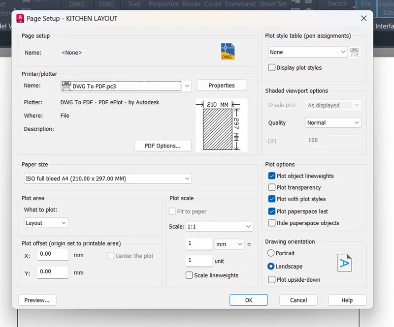
- In page setup manager, select the kitchen layout, select the modify option, and modify the setting as shown below.
- Type MV in command box, press enter, select the 4 option from command box, option . specify first point and second point.
- In modal space, type V in command box, press enter, select the new option from view manager dialog box, give the name to view as V1 and select define window option and in modal space define the view using the window.
- Similarly create the view naming V2, V3 and V4 by following the same procedure.
- Go to the paper space, type MS in command box press enter, select the first viewport and type V in command box and press enter.
- Select the standard scale from scale of status bar such that view fit inside the viewport.
- Type PAN in command box, press enter and adjust the view such that it fit inside the viewport.
- Type PS in command box, press enter, select the viewport, right click, and lock the display.
- Type ST in command box, press enter, select the font name arial with the height as 0 units and select ok.
- Type DT in command box, press enter, specify rotation angle as 0 and type the text as per required content as SCALE – 1:1.
- Type CO in command box, press enter, select the just written text, press enter, select the base point and copy it to the required position.
- Type ED in command box, press enter, select the text required to edit and edit it as per required content.
- Go to layout tab, right click on layout tab and select the plot option, select continue to plot single sheet, check the settings and select the preview option and see the preview.
- Right click on preview and select the plot option, give the file name and save it in desired folder.
Result:
Layout of kitchen created in challenge 9 in AutoCAD software using above mentioned procedure is shown below.
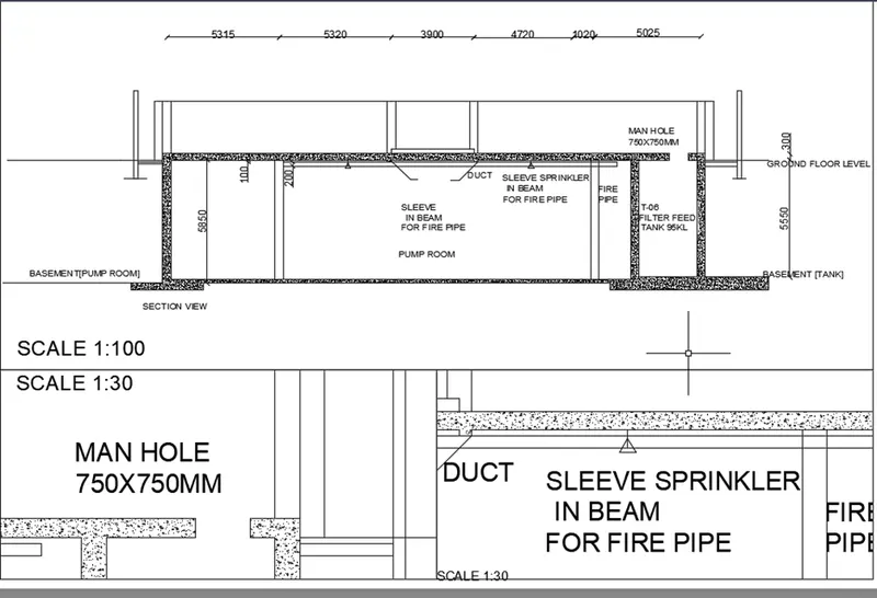
- Aim: To create Multiview ports for industrial section drawing, scaling it and making it a plot. Scale 1:30 and 1:100 is given.
Procedure:
- Open the drawing of section of industrial building.
- Take the layout tab.
- Rename the tab as industrial section.
- Right click on the tab and select page setup manager option.
- Click on new-give a name, page setup dialogue appears.
- Give the paper size as A3 in page setup.
- Make it current, the layout paper size changes to A3.
- Create the viewport by MV command and giving a scale of 1:100 and 1:30.
- Use "MV" command and create 3 viewports accordingly.
- Use command "MS" for model space and click on first viewport.
- Set the scale to 1:100 from the bottom toolbar or right click and properties and from there we can change the scale.
- By Pan command fit the drawing inside the viewport.
- By text command write the text as SCALE 1:100 with a text height of 50 and lock the viewport.
- Go to model view and create the views for the next two viewports.
- Create views for sprinkler and as sprinkler view.
- Now go to the layout industrial section and command "ms" and click on the left model space.
- Now use the command "view" select the manhole view and click on set current.
- Then the view will be displayed on the model space.
- Select the scale to 1:30 from bottom toolbar.
- By multiline text give the text scale as 1:30
- Lock the viewport from the bottom toolbar lock symbol.
- Type "MS" click on third viewport.
- Use command "VIEW" and select the sprinkler view and make it current.
- Select the scale to 1:30 from the bottom toolbar.
- By multiline text insert the text as Scale 1:30.
- Lock the viewport.
- Click on preview option to see the preview and apply to layout.
Result:
Layout of section created in challenge 9 in AutoCAD software using above mentioned procedure is shown below.