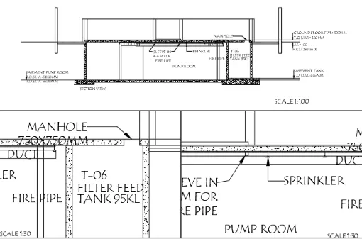
Creation of Multiple viewports, Scaling the drawing and setting in Template in AutoCad
CREATING OF MULTIPLE VIEWPORT, SCALING THE DRAWING IN TEMPLATE IN AUTOCAD
1. CREATE A LAYOUT OF PLAN AND SECTION
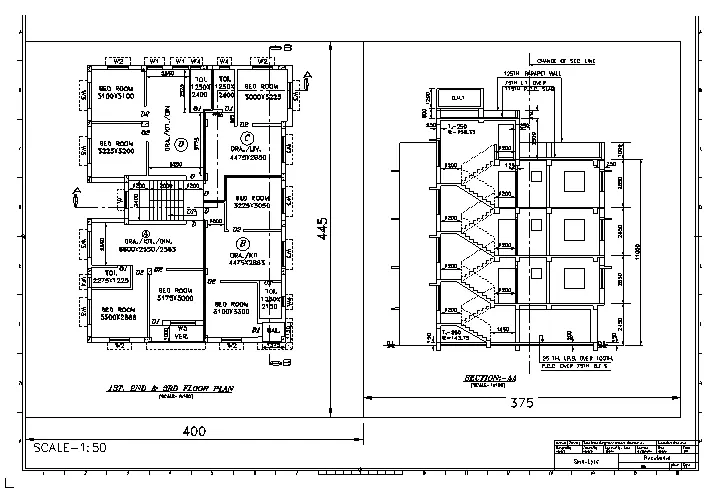
AIM - TO DRAFT A LAYOUT OF PLAN AND SECTION USING AUTOCAD.
INTODUCTION-
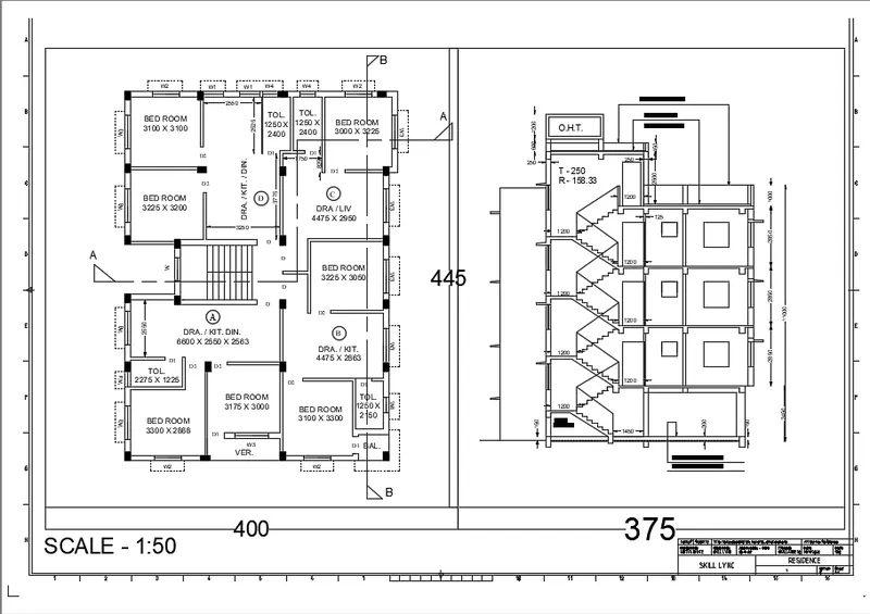
The layout of plan and section A of the project in challenges 7 is created using a AutoCAD software. the template use for layout is mArch.dwtand scale are given in figures.
TOOLS USED-
- LINE - Command for line is L
- CONSTRUCTTION LINE - Command for construcction line is XL
- TRIM - Command for trim is TR
- TEXT- Command for text is DTEXT/MTEXT
- DIMENSION - Command for line is Dimension DIM
- OFFSET - Command for offset is O
- FILLET - Command for fillet is F
- SPLINE - Command for spline is SPL
- LAYERS -Command for layer is LA
- CIRCLE - Command for circle is C
- RECTANGLE - Command for the rectangle is REC
- HATCH - Command for hatch is H
- ARC - Command for arc is A
- ARROW - Command for arrow is LE
PROCEDURE -
STEP 1
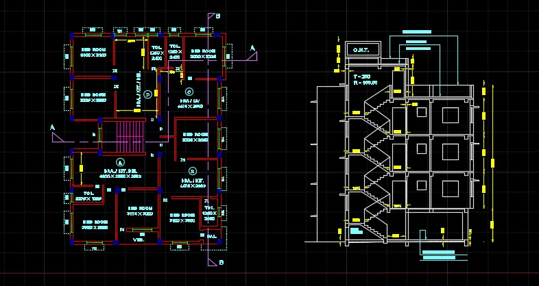
- Open the file created in challenges 7 and copy the pland and section A and paste in new file
STEP 2
- Click on layout at the bottom of the screen and select a template as march.dwt
e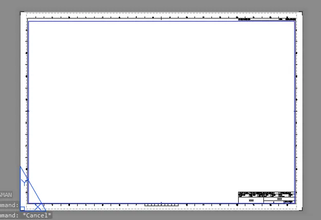
STEP 3
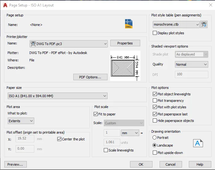
- Right click on layout and select page set up and select a name of printer as DWG to PDF
- paper size as ISO A1
- and select a monochrome.ctb in Plot style table
STEP 4
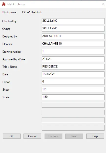
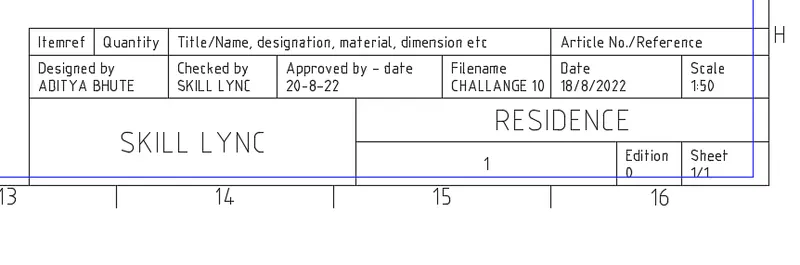
- ATTEDIT is the command for edit attributes table
- give the command and and change all the block name as per required
STEP 6
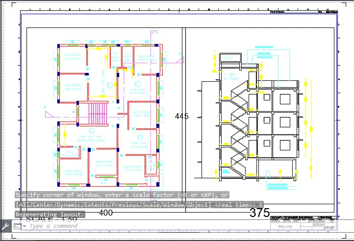
- MV is command for multipal viewport draw a two viewport of size 400 x 445 and 375 x 445
- for scale the image type ms to zoom in model port and scale accourding to our use and again type ps to return into paper space
RESULT -
2. CREATE A LAYOUT OF THE KITCHEN
AIM - TO DRAFT A LAYOUT OF KITCHEN USING AUTOCAD.
INTODUCTION-
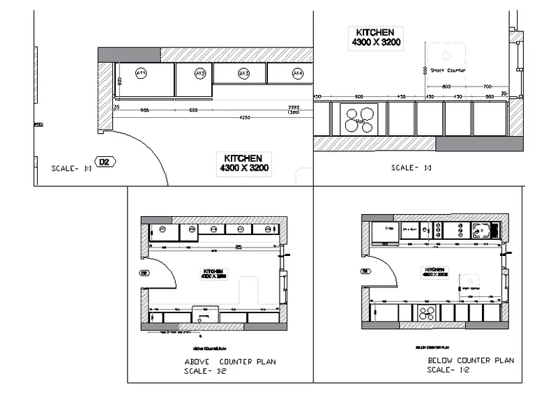
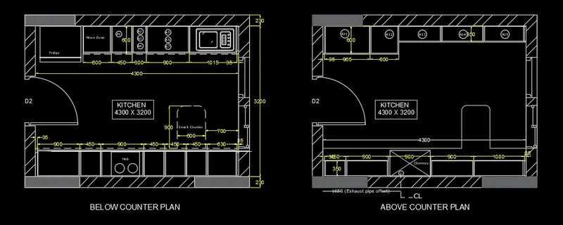
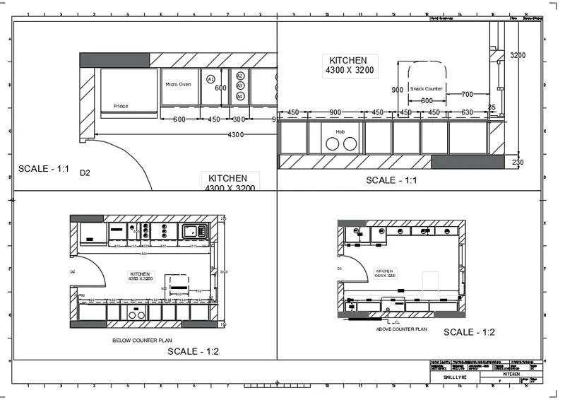
The layout of Kitchen of the project in challenges 9 is created using a AutoCAD software. the template use for layout is mArch.dwtand scale are given in figures.
TOOLS USED-
- LINE - Command for line is L
- CONSTRUCTTION LINE - Command for construcction line is XL
- TRIM - Command for trim is TR
- TEXT- Command for text is DTEXT/MTEXT
- DIMENSION - Command for line is Dimension DIM
- OFFSET - Command for offset is O
- FILLET - Command for fillet is F
- SPLINE - Command for spline is SPL
- LAYERS -Command for layer is LA
- CIRCLE - Command for circle is C
- RECTANGLE - Command for the rectangle is REC
- HATCH - Command for hatch is H
- ARC - Command for arc is A
- ARROW - Command for arrow is LE
PROCEDURE -
STEP 1
- Open the file created in challenges 9 and copy the pland and section A and paste in new file
STEP 2
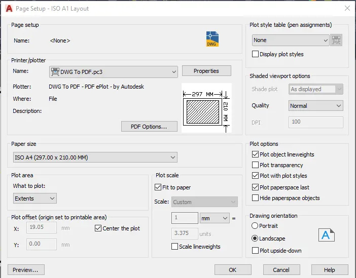
- Right click on layout and select page set up and select a name of printer as DWG to PDF
- paper size as ISO A1
- and select a monochrome.ctb in Plot style table
STEP 3
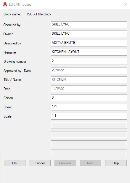
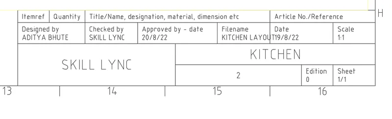
- ATTEDIT is the command for edit attributes table
- give the command and and change all the block name as per required
RESULT -
3. CREATE A LAYOUT OF SECTION VIEW
AIM - TO DRAFT A LAYOUT OF SECTION USING AUTOCAD.
INTODUCTION-
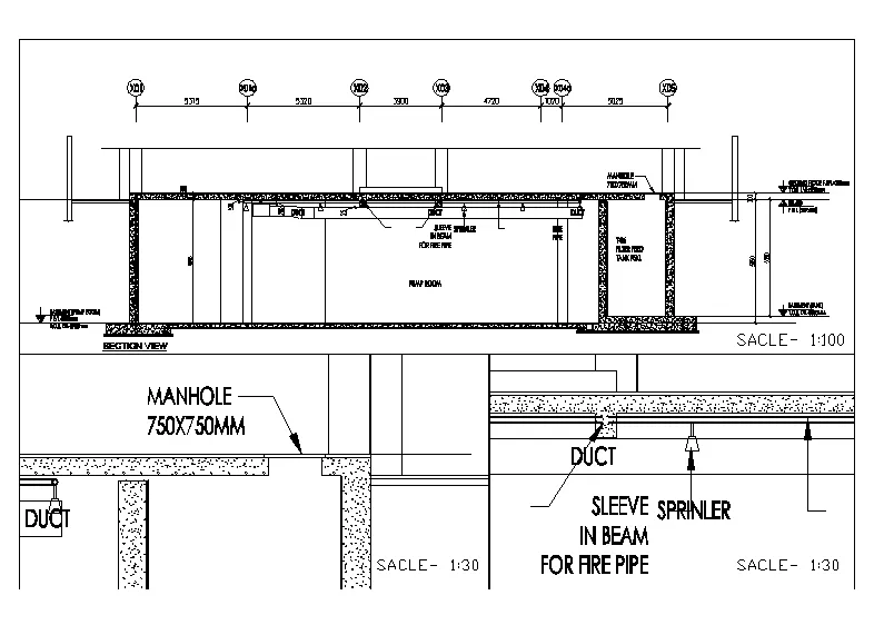
The layout oF section of the project in challenges 9 is created using a AutoCAD software. the template use for layout is mArch.dwtand scale are given in figures.
TOOLS USED-
- LINE - Command for line is L
- CONSTRUCTTION LINE - Command for construcction line is XL
- TRIM - Command for trim is TR
- TEXT- Command for text is DTEXT/MTEXT
- DIMENSION - Command for line is Dimension DIM
- OFFSET - Command for offset is O
- FILLET - Command for fillet is F
- SPLINE - Command for spline is SPL
- LAYERS -Command for layer is LA
- CIRCLE - Command for circle is C
- RECTANGLE - Command for the rectangle is REC
- HATCH - Command for hatch is H
- ARC - Command for arc is A
- ARROW - Command for arrow is LE
PROCEDURE -
STEP 1
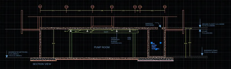
- Open the file created in challenges 9 and copy the pland and section A and paste in new file
STEP 2
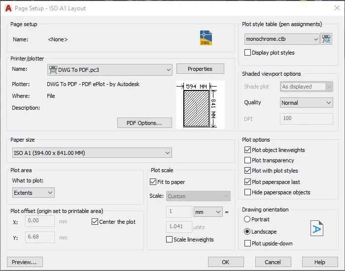
- Right click on layout and select page set up and select a name of printer as DWG to PDF
- paper size as ISO A1
- and select a monochrome.ctb in Plot style table
STEP 3-
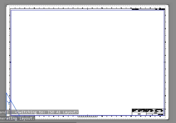
- ATTEDIT is the command for edit attributes table
- give the command and and change all the block name as per required
STEP 4-
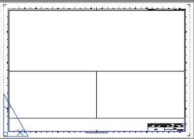
- MV is command for multipal viewport draw a Three viewport
- for scale the image type ms to zoom in model port and scale accourding to our use and again type ps to return into paper space
RESULT -