Creation of Multiple viewports, Scaling the drawing and setting in Template in AutoCad
1)
Aim:
layout of the Plan and Section A of the project in Challenges 7, using the template Tutorial-mArch.dwt in a scale as given in the Figure. Use the MV command to create the viewport of the size as shown in Figure. Also, use ATTEDIT command to edit the information in the title block. Use A1 size for the layout. Take a plot.
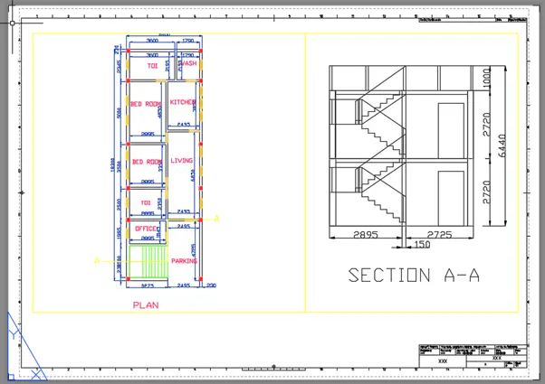
I. In command prompt type (startup:1)
II. Then file>new
III. Then create new drawing window select metric in default settings
IV. In advanced setup in units check on the decimal, angle in degrees, then ok
V. Go to insert toolbar and select the import pdf option and
VI. Import the required pdf
VII. Select the whole imported file and type scale in prompt bar to activate the scale option
VIII. By keeping the exterior wall as the reference calculate the scale factor
IX. Now select the basepoint
X. And enter the scale factor enter
XI. Now create a layer naming the reference and draw the lines and arc over the layout for the required floor plan with the help of the snapping
XII. In command prompt type v: view and
XIII. Create new view of the required boundary and name it as plan
XIV. Create new view of the required boundary and name it as section
XV. Go to layout and type ps in command prompt and erase all the contents present
XVI. Type page setup manager and the set the page top A1
XVII. Right click on the layout and rename it to desired name
XVIII. Again, right click and go to the from template and select the march template
XIX. Type MV in the command prompt and
XX. Create the viewports of the desired dimensions
XXI. Type v in the command prompt
XXII. Select the viewport and apply the view that assigned for the respective viewports
XXIII. Select the view port and by arrow down grip change it to the required scale
XXIV. Respectively for all the viewports
XXV. If any of the unwanted lines are visible in the viewport
XXVI. Type MS in the viewport and enter to the model space
XXVII. Type LA in the command prompt and the layer turnoff/freeze the all vplayer that should be hidden
XXVIII. And the with attdef define the attribute inside thelegend and create the legend as the block
Result:
Required layout is created in the March templete
2)
Aim:
layout of the Kitchen drawn in Challenge 9 as shown in Figure. Use the scale as shown in the Figure. Use A4 Size page for the layout.
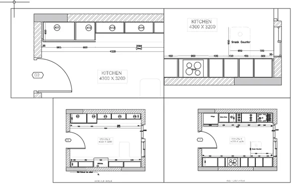
I. In command prompt type (startup:1)
II. Then file>new
III. Then create new drawing window select metric in default settings
IV. In advanced setup in units check on the decimal, angle in degrees, then ok
V. Go to insert toolbar and select the import pdf option and
VI. Import the required pdf
VII. Select the whole imported file and type scale in prompt bar to activate the scale option
VIII. By keeping the exterior wall as the reference calculate the scale factor
IX. Now select the basepoint
X. And enter the scale factor enter
XI. Now create a layer naming the reference and draw the lines and arc over the layout for the required floor plan with the help of the snapping
XII. In command prompt type v: view and
XIII. Create new view of the required boundary and name it as 1
XIV. Create new view of the required boundary and name it as 2
XV. Create new view of the required boundary and name it as 3
XVI. Create new view of the required boundary and name it as 4
XVII. Go to layout and type ps in command prompt and erase all the contents present
XVIII. Type page setup manager and the set the page top A4
XIX. Right click on the layout and rename it to desired name
XX. Type MV in the command prompt and
XXI. Create the viewports of the desired dimensions
XXII. Type v in the command prompt
XXIII. Select the viewport and apply the view that assigned for the respective viewports
XXIV. Select the view port and by arrow down grip change scale to 1.1 for viewport 1
XXV. Select the view port and by arrow down grip change scale to 1.1 for viewport 2
XXVI. Select the view port and by arrow down grip change scale to 1.2 for viewport 3
XXVII. Select the view port and by arrow down grip change scale to 1.2 for viewport 4
XXVIII. Respectively for all the viewports
XXIX. If any of the unwanted lines are visible in the viewport
XXX. Type MS in the viewport and enter to the model space
XXXI. Type LA in the command prompt and the layer turnoff/freeze the all vplayer that should be hidden
Result:
Required layout of the kitchen layout was shown in the viewports
3)
Aim:
layout of the section created in Challenges 9. With Use scale as mentioned in the Figure. Using MV command create multiple viewports.
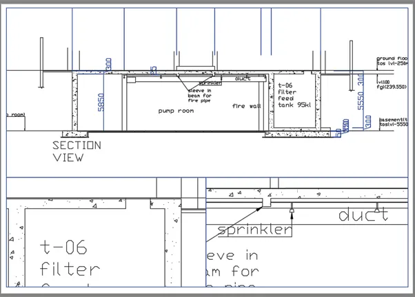
I. In command prompt type (startup:1)
II. Then file>new
III. Then create new drawing window select metric in default settings
IV. In advanced setup in units check on the decimal, angle in degrees, then ok
V. Go to insert toolbar and select the import pdf option and
VI. Import the required pdf
VII. Select the whole imported file and type scale in prompt bar to activate the scale option
VIII. By keeping the exterior wall as the reference calculate the scale factor
IX. Now select the basepoint
X. And enter the scale factor enter
XI. Now create a layer naming the reference and draw the lines and arc over the layout for the required floor plan with the help of the snapping
XII. In command prompt type v: view and
XIII. Create new view of the required boundary and name it as 1
XIV. Create new view of the required boundary and name it as 2
XV. Create new view of the required boundary and name it as 3
XVI. Go to layout and type ps in command prompt and erase all the contents present
XVII. Type page setup manager and the set the page top A4
XVIII. Right click on the layout and rename it to desired name
XIX. Type MV in the command prompt and
XX. Create the viewports of the desired dimensions
XXI. Type v in the command prompt
XXII. Select the viewport and apply the view that assigned for the respective viewports
XXIII. Select the view port and by arrow down grip change scale to 1.100 for viewport 1
XXIV. Select the view port and by arrow down grip change scale to 1.30 for viewport 2
XXV. Select the view port and by arrow down grip change scale to 1.30 for viewport 3
XXVI. Respectively for all the viewports
XXVII. If any of the unwanted lines are visible in the viewport
XXVIII. Type MS in the viewport and enter to the model space
XXIX. And type ps and edit all required elements in the paper space
XXX. Type LA in the command prompt and the layer turnoff/freeze the all vplayer that should be hidden
Result:Layout of the section of the multiple viewports was draw in the layout of the AutoCAD templete