Creation of geometries by Coordinate system methods using AutoCad
AIM:
Creation of geometries by Coordinate system methods using AutoCAD
INTRODUCTION:
TYPES OF COORDINATE SYSTEM
1. ABSOULTE COORDINATE SYSTEM
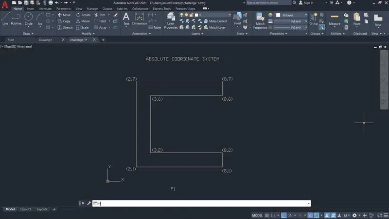
Absolute coordinate entry always counts from the origin. When drawing lines, AutoCAD is ready to place the next vertex wherever you tell it to go
2.RELATIVE COORDINATE SYSTEM
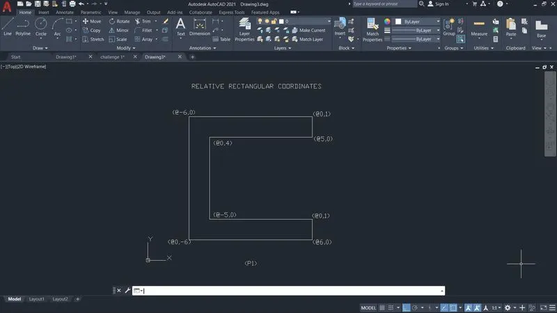
i) Relative rectangular coordinate system
For relative coordinates, AutoCAD does not count from (0,0). Instead, the reference point is the previous point in the drawing
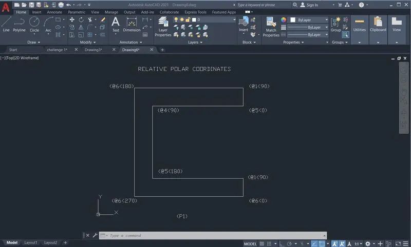
ii) Relative rectangular coordinate system
Polar coordinates are named for their “pole”; the reference point to start counting from, which is similar in concept to the origin. Polar coordinates employ one radial distance and one angle (by convention, the angle is measured counter clockwise from the x-axis). The angle signifies the direction, and the distance is how far to go in that direction from the pole.
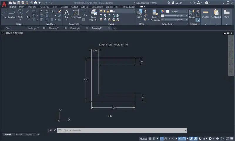
3.DIRECT DISTANCE ENTRY
Direct distance entry enables you to draw an object, such as a line, by pointing in a particular direction with the cursor and entering a distance at the command line.
PROCEDURE
1.Creating the geometries from P1 to P2 using all the coordinates system methods
P1 - Absolute coordinate system
P1- Relative rectangular coordinates
P1- Relative polar coordinates
P1- Direct distance entry
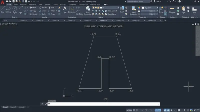
P2- Absolute coordinate method
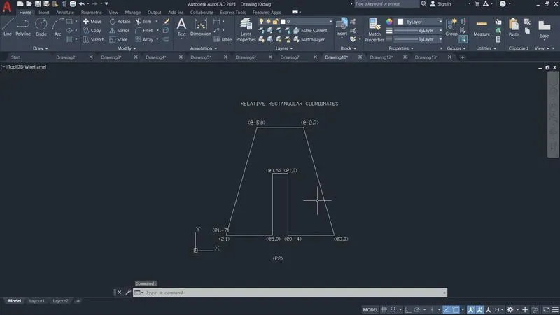
P2- Relative rectangular coordinates
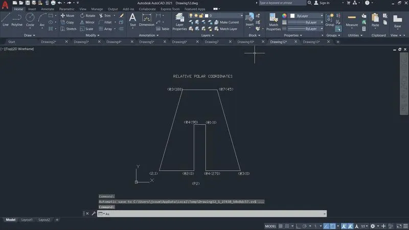
P2- Relative polar coordinates
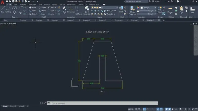
P2- Direct distance entry
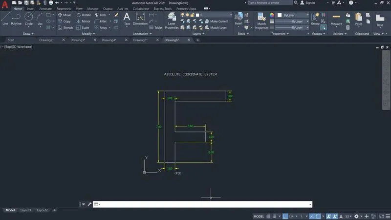
P3 - Absolute coordinate method
- Choose the line tool
- Specify first point 2,1
- Specify next point 3,1
- Specify next point 3,3
- Specify next point 6,3
- Specify next point 6,4
- Specify next point 3,4
- Specify next point 3,7
- Specify next point 8,7
- Specify next point 8,8
- Specify next point 2,8
- Specify end point 2,1
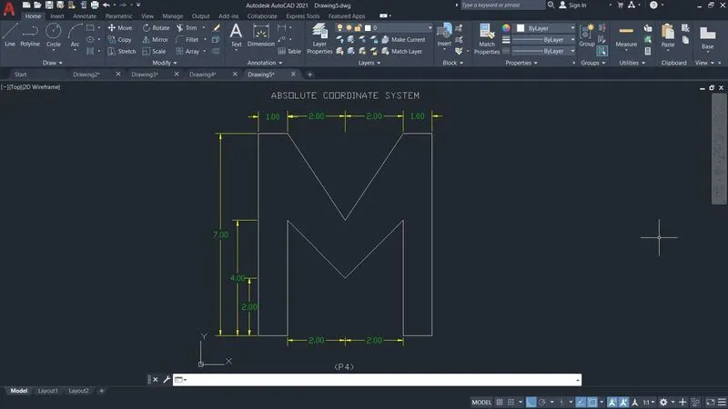
P4- Absolute coordinate method
- Choose the line tool
- Specify first point 2,1
- Specify next point 3,1
- Specify next point 3,5
- Specify next point 5,2
- Specify next point 7,5
- Specify next point 7,1
- Specify next point 8,1
- Specify next point 8,8
- Specify next point 7,8
- Specify next point 5,5
- Specify next point 3,8
- Specify next point 2,8
- Specify end point 2,1
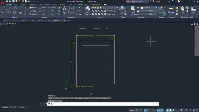
P5 - Absolute coordinate method
- Choose the line tool
- Specify first point 2,1
- Specify next point 3,1
- Specify next point 3,8
- Specify next point 8,8
- Specify next point 8,2
- Specify next point 5,2
- Specify next point 5,1
- Specify next point 9,1
- Specify next point 9,9
- Specify next point 2,9
- Specify end point 2,1
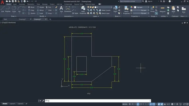
P6- Absolute coordinate method
- Choose the line tool
- Specify first point 2,1
- Specify next point 6,1
- Specify next point 10,4
- Specify next point 10,6
- Specify next point 6,6
- Specify next point 6,10
- Specify next point 2,10
- Specify end point 2,1enter
- Specify next point 3,3
- Specify next point 3,6
- Specify next point 5,6
- Specify next point 5,3
- Specify end point 3,3
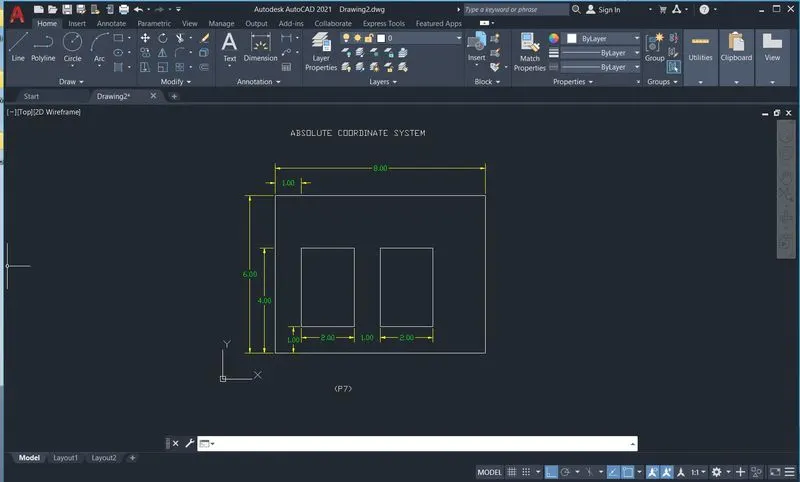
P7- Absolute coordinate method
- Choose the line tool
- Specify first point 2,1
- Specify next point 10,1
- Specify next point 10,7
- Specify next point 2,7
- Specify end point 2,1 enter
- Specify next point 3,2
- Specify next point 5,2
- Specify next point 5,5
- Specify next point 3,5
- Specify end point 3,2n enter
- Specify next point 6,2
- Specify next point 8,2
- Specify end point 8,5
- Specify next point 6,5
- Specify end point 6,2
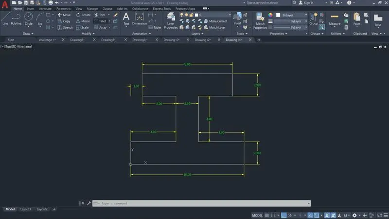
P8- Absolute coordinate method
- Choose the line tool
- Specify first point 0,0
- Specify next point 10,0
- Specify next point 10,2
- Specify next point 6,2
- Specify next point 6,6
- Specify next point 9,6
- Specify next point 9,8
- Specify next point 1,8
- Specify next point 1,6
- Specify next point 4,6
- Specify end point 4,2
- Specify next point 0,2
- Specify end point 0,0
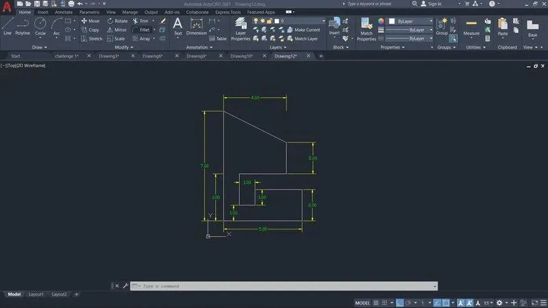
P9- Absolute coordinate method
- Choose the line tool
- Specify first point 1,1
- Specify next point 10,0
- Specify next point 10,2
- Specify next point 6,2
- Specify next point 6,6
- Specify next point 9,6
- Specify next point 9,8
- Specify next point 1,8
- Specify next point 1,6
- Specify next point 4,6
- Specify end point 4,2
- Specify next point 0,2
- Specify end point 1,1
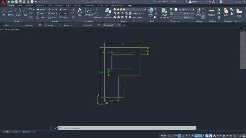
P10- Absolute coordinate method
- Choose the line tool
- Specify first point 1,1
- Specify next point 6,1
- Specify next point 6,3
- Specify next point 3,3
- Specify next point 3,2
- Specify next point 2,2
- Specify next point 2,4
- Specify next point 5,4
- Specify next point 5,6
- Specify next point 1,8
- Specify end point 1,1
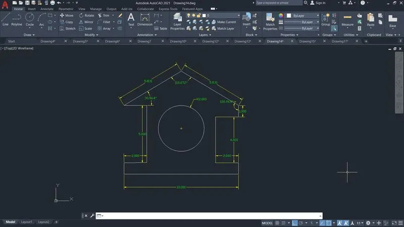
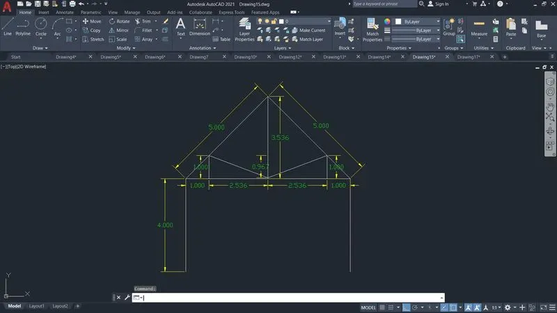
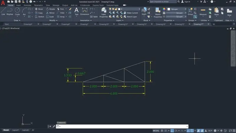
II. Draw the profile and the trusses using any coordinate system method
Direct distance method
RESULT :
Creation of geometries are done by Coordinate system methods using AutoCAD