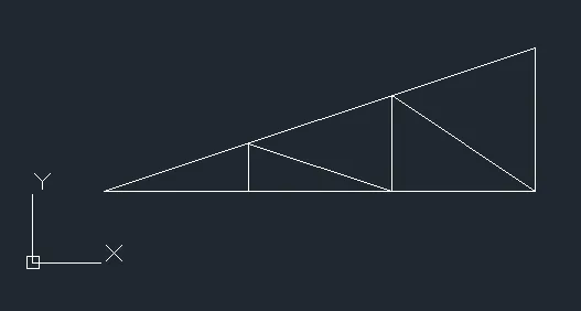
Creation of geometries by Coordinate system methods using AutoCad
Aim: Create the geometries from P1 to P2 using all the coordinates system methods and for P3, P4, P5, P6, P7, P8, P9, P10 use any one coordinate system and use the Line tool to create the geometries, Where required, use the circle tool.
Introduction:
- AutoCAD was derived from a program that began in 197, and then released in 1979 called interCAD, also referred to in early Autodesk documents as MicroCAD, which was written before Autodesk's (then marinchip software partner) formation by Autodesk cofounder Micheal Riddle. The first version of AutoCAD was demonstrated at 1982 Comdex and released that December. AutoCAD supported CP/M-80 computers.
- As AutoCAD's flagship product by March 986, AutoCAD had become the most ubiquitous CAD program worldwide.
- The fundamental purpose of AutoCAD is to create lines, arcs, circles, and other geometric shapes that are necessary for the phase of producing clean drawings that are free from errors.
- The line tool in AutoCAD create straight line segments. With line, a series of lines that are parallel, collinear, intersecting, and more can be made. Every line segment that is created using this tool can be later edited separately.
- Different coordinate systems used are:
a) Absolute coordinate system - All the points are taken concerning origin.
b) Relative coordinate system - The points are taken concerning the last point.
i) Relative rectangular coordinate system
ii) Relative polar coordinate system
c) Direct distance entry - It enables you to draw an object, such as a line, by pointing in a particular direction with the cursor and entering a distance at the command line.
Procedure for P1:
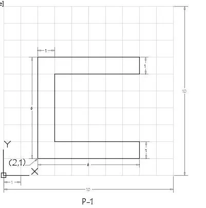
Steps of creating geometry in AutoCAD Software by Absolute coordination system for P1:
- Open the AutoCAD application, Setup up the units to the imperial template and the decimal system.
- Set up the limits in the command tab using LIM before drafting.
- Type the command "L" for the line and specify
- Specify the first coordinates for starting point 1 (2,1)
- Specify next point 2 (8,1)
- Specify next point 3 ( 8,2)
- Specify next point 4 (3,2)
- Specify next point 5 (3,6)
- Specify next point 5 (8,6)
- Specify next point 7 (8,7)
- Specify next point 8 (2,7)
- Command: *Cancel*
Steps of creating geometry in AutoCAD Software by Relative rectangular coordinate system for P1:
- Type the command "L" for the line and specify
- Specify the first coordinates for starting point 1 (2,1)
- Specify next point @6,0
- Specify next point @0,1
- Specify next point @-5,0
- Specify next point @0,4
- Specify next point @5,0
- Specify next point @0,1
- Specify next point @-6,0
- Specify next point C
- Command: *Cancel*
Steps of creating geometry in AutoCAD Software by Relative polar coordinate system for P1:
- Type the command "L" for the line and specify
- Specify the first coordinates for a starting point (2,1)
- Specify next point @6<0
- Specify next point @1<90
- Specify next point @5<180
- Specify next point @4<90
- Specify next point @5<0
- Specify next point @1<90
- Specify next point @6<180
- Specify next point C
- Command: *Cancel*
Steps of creating geometry in AutoCAD Software by Direct distance entry for P1:
- Type the command "L" for the line and specify
- Specify the first coordinates for a starting point (2,1)
- Line specify the next point: 6 (Towards East)
- Line specify the next point: 1 (Towards North)
- Line specify the next point: 5 (Towards West)
- Line specify the next point: 4 (Towards North)
- Line specify the next point: 5 (Towards East)
- Line specify the next point: 1 (Towards North)
- Line specify the next point: 6 (Towards West)
- Line specify the next point: Type 'C' for close or point 6 (Towards South)
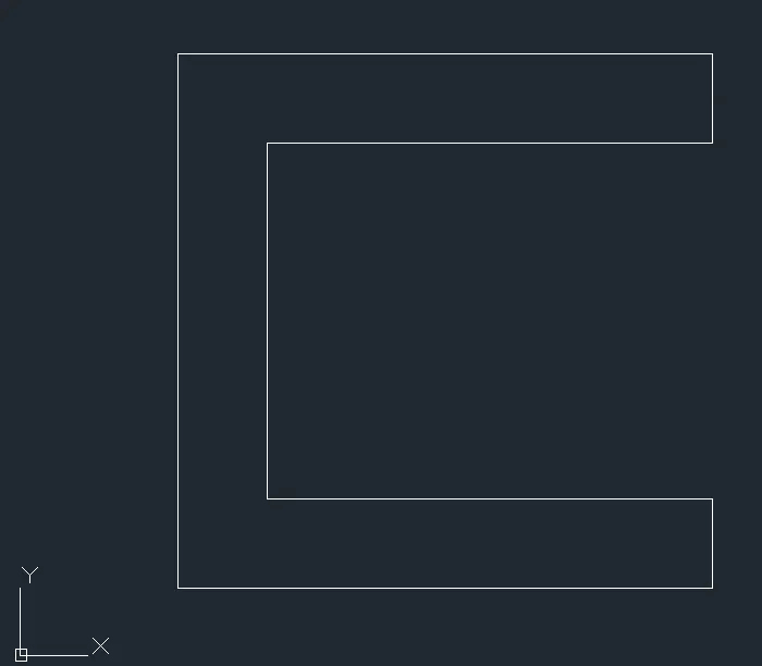
Result:
Procedure for P2:
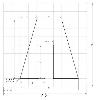
Steps of creating geometry in AutoCAD Software by Absolute coordination system for P2:
- Type the command "L" for the line and specify
- Specify the first coordinates for a starting point (2,1)
- Specify next point 2 (5,1)
- Specify next point 3 ( 5,5)
- Specify next point 4 (6,5)
- Specify next point 5 (6,1)
- Specify next point 5 (9,1)
- Specify next point 7 (7,8)
- Specify next point 8 (4,8)
- Command: *Cancel*
Steps of creating geometry in AutoCAD Software by Relative rectangular coordinate system for P2:
- Type the command "L" for the line and specify
- Specify the first coordinates for starting point 1 (2,1)
- Specify next point @3,0
- Specify next point @0,4
- Specify next point @1,0
- Specify next point @0,-4
- Specify next point @3,0
- Specify next point @-2,7
- Specify next point @-3,0
- Specify next point C
- Command: *Cancel*
Steps of creating geometry in AutoCAD Software by Relative polar coordinate system for P2:
- Type the command "L" for the line and specify
- Specify the first coordinates for a starting point A (2,1)
- Specify next point B @3<0
- Specify next point C @4<90
- Specify next point D @1<0
- Specify next point E @4<270
- Specify next point F @3<0
- Specify next point G @7<90
- Specify next point H @2<180
- Specify next point I @3<180 ( join A and I then erase HG line segment later join FG then delete FH)
- Specify next point C
- Command: *Cancel*
Steps of creating geometry in AutoCAD Software by Direct distance entry for P2:
- Type the command "L" for the line and specify
- Specify the first coordinates for a starting point (2,1)
- Line specify the next point A: 3 (Towards East)
- Line specify the next point B: 4 (Towards North)
- Line specify the next point C: 1 (Towards East)
- Line specify the next point D: 4 (Towards South)
- Line specify the next point E: 3 (Towards East)
- Line specify the next point F: 7 (Towards North)
- Line specify the next point G: 2 (Towards West)
- Specify next point I: 3 (Join A and I then erase HG line segment later join FG then delete FH)
- Specify next point C
- Command: *Cancel*
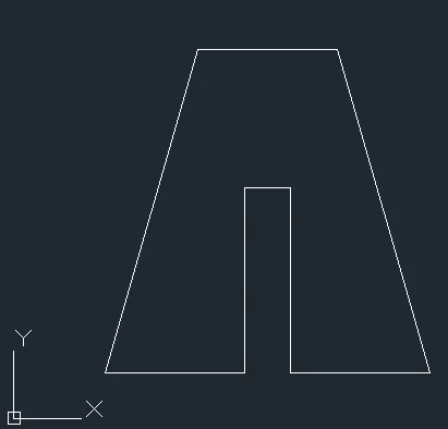
Result:
Procedure for P3:
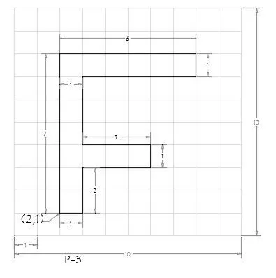
Steps of creating geometry in AutoCAD Software by Absolute coordination system for P3:
- Type the command "L" for the line and specify
- Specify the first coordinates for a starting point (2,1)
- Specify next point 2 (3,1)
- Specify next point 3 ( 3,3)
- Specify next point 4 (6,3)
- Specify next point 5 (6,4)
- Specify next point 5 (3,4)
- Specify next point 7 (3,7)
- Specify next point 8 (8,7)
- Specify next point 9 (8,8)
- Specify next point 10 (2,8)
- Command: *Cancel*
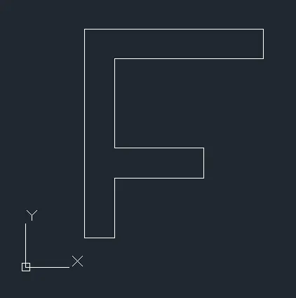
Result:
Procedure for P4:
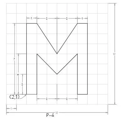
Steps of creating geometry in AutoCAD Software by Relative rectangular coordinate system for P4:
- Type the command "L" for the line and specify
- Specify the first coordinates for starting point 1 (2,1)
- Specify next point @1,0
- Specify next point @0,4
- Specify next point @2,-2
- Specify next point @2,2
- Specify next point @0,-4
- Specify next point @1,0
- Specify next point @0,7
- Specify next point @-1,0
- Specify next point @-2,-3
- Specify next point @-2,3
- Specify next point @-1,0
- Specify next point C
- Command: *Cancel*
Result:

Procedure for P5:
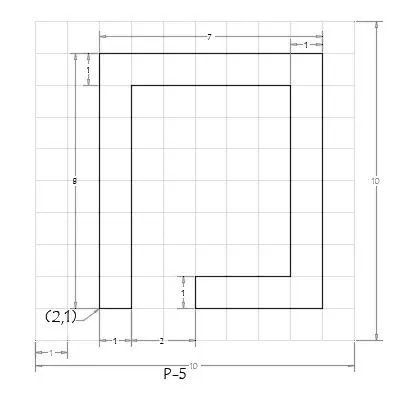
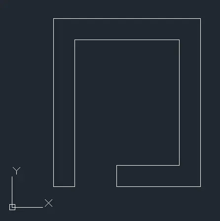
Steps of creating geometry in AutoCAD Software by Relative polar coordinate system for P5:
- Type the command "L" for the line and specify
- Specify the first coordinates for a starting point A (2,1)
- Specify next point B @1<0
- Specify next point C @7<90
- Specify next point D @5<0
- Specify next point E @6<270
- Specify next point F @3<180
- Specify next point G @1<270
- Specify next point H @4<0
- Specify next point I @8<90
- Specify next point J @7<180
- Specify next point C
- Command: *Cancel*
Result:
Procedure for P6:
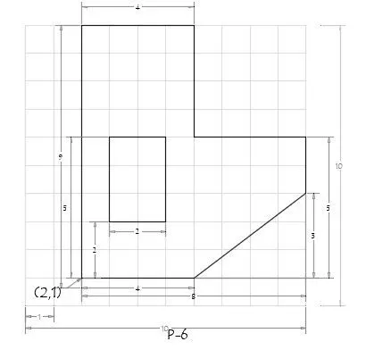
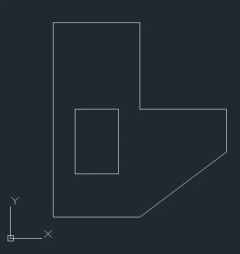
Steps of creating geometry in AutoCAD Software by Direct distance entry for P6:
- Type the command "L" for the line and specify
- Specify the first coordinates for a starting point (2,1)
- Line specify the next point A: 4 (Towards East)
- Line specify the next point B: 4 (Towards East)
- Line specify the next point C: 3 (Towards North)
- Line specify the next point D: 2 (Towards North)
- Line specify the next point E: 4 (Towards West)
- Line specify the next point F: 4 (Towards North)
- Line specify the next point G: 4 (Towards West)
- Line specify the next point H: 4 (Towards South)
- Line specify the next point I: 3 (Towards South)
- Line specify the next point J: 2 (Towards South) (A and J joined)
- Command: *Cancel*
- Line specify the next point K: 1 (Towards East) ( Take a line from the I to east)
- Line specify the next point L: 2 (Towards East)
- Line specify the next point M: 3 (Towards North)
- Line specify the next point N: 2 (Towards West)
- Line specify the next point O: 3 (Towards South) (L and O joined then erase KL)
- Command: *Cancel*
- BC and CD line segments erased then join B point to C point
- Specify next point C
- Command: *Cancel*
Result:
Procedure for P7:
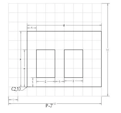
Steps of creating geometry in AutoCAD Software by Absolute coordination system for P7:
- Type the command "L" for the line and specify
- Specify the first coordinates for starting point 1 (2,1)
- Specify next point 2 (10,1)
- Specify next point 3 ( 10,7)
- Specify next point 4 (2,7)
- Command: *Cancel*
- Type the command "L" for the line Specify next point 5 (3,2)
- Specify next point 6 (5,2)
- Specify next point 7 (5,5)
- Specify next point 8 (3,5)
- Command: *Cancel*
- Type the command "L" for the line Specify next point 9 (6,2)
- Specify next point 10 (8,2)
- Specify next point 11 (8,5)
- Specify next point 12 (6,5)
- Command: *Cancel*
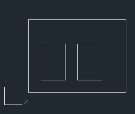
Result:
Procedure for P8:
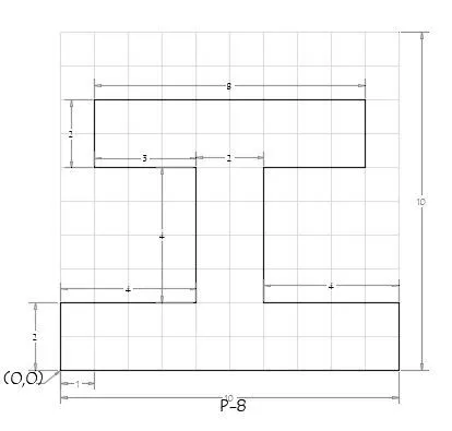
Steps of creating geometry in AutoCAD Software by Relative rectangular coordinate system for P8:
- Type the command "L" for the line and specify
- Specify the first coordinates for starting point 1 (0,0)
- Specify next point @10,0
- Specify next point @0,2
- Specify next point @-4,0
- Specify next point @0,4
- Specify next point @3,0
- Specify next point @0,2
- Specify next point @-8,0
- Specify next point @0,-2
- Specify next point @3,0
- Specify next point @0, -4
- Specify next point @-4,0
- Specify next point C
- Command: *Cancel*
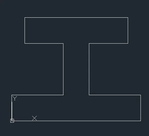
Result:
Procedure for P9:
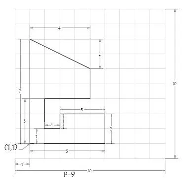
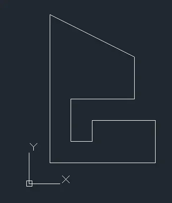
Steps of creating geometry in AutoCAD Software by Relative polar coordinate system for P9:
- Type the command "L" for the line and specify
- Specify the first coordinates for a starting point A (1,1)
- Specify next point B @5<0
- Specify next point C @2<90
- Specify next point D @3<180
- Specify next point E @1<270
- Specify next point F @1<180
- Specify next point G @2<90
- Specify next point H @3<0
- Specify next point I @2<90
- Specify next point J @2<90
- Specify next point K @4<180
- Command: *Cancel*
- Type the command "L" for the line ( erase IJ and JK line segment then join the K and I points)
- Specify next point C
- Command: *Cancel*
Result:
Procedure for P10:
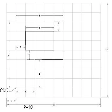
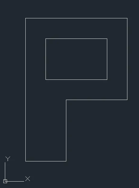
Steps of creating geometry in AutoCAD Software by Direct distance entry for P10:
- Type the command "L" for the line and specify
- Specify the first coordinates for a starting point (1,1)
- Line specify the next point A: 2 (Towards East)
- Line specify the next point B: 3 (Towards North)
- Line specify the next point C: 4 (Towards East)
- Line specify the next point D: 5 (Towards North)
- Specify next point C
- Command: *Cancel*
- Type the command "L" for the line and specify
- Specify the first coordinates for a starting point (2,5)
- Line specify the next point E: 3 (Towards East)
- Line specify the next point F: 2 (Towards North)
- Line specify the next point G: 3 (Towards West)
- Specify next point C
- Command: *Cancel*
Result:
Aim: Draw the profile and the trusses using any coordinate system methods.
Introduction:
- AutoCAD was derived from a program that began in 197, and then released in 1979 called interCAD, also referred to in early Autodesk documents as MicroCAD, which was written before Autodesk's (then marinchip software partner) formation by Autodesk cofounder Micheal Riddle. The first version of AutoCAD was demonstrated at 1982 Comdex and released that December. AutoCAD supported CP/M-80 computers.
- As AutoCAD's flagship product by March 986, AutoCAD had become the most ubiquitous CAD program worldwide.
- The fundamental purpose of AutoCAD is to create lines, arcs, circles, and other geometric shapes that are necessary for the phase of producing clean drawings that are free from errors.
- The line tool in AutoCAD create straight line segments. With line, a series of lines that are parallel, collinear, intersecting, and more can be made. Every line segment that is created using this tool can be later edited separately.
- Different coordinate systems used are:
a) Absolute coordinate system - All the points are taken concerning origin.
b) Relative coordinate system - The points are taken concerning the last point.
i) Relative rectangular coordinate system
ii) Relative polar coordinate system
c) Direct distance entry - It enables you to draw an object, such as a line, by pointing in a particular direction with the cursor and entering a distance at the command line.
Procedure:
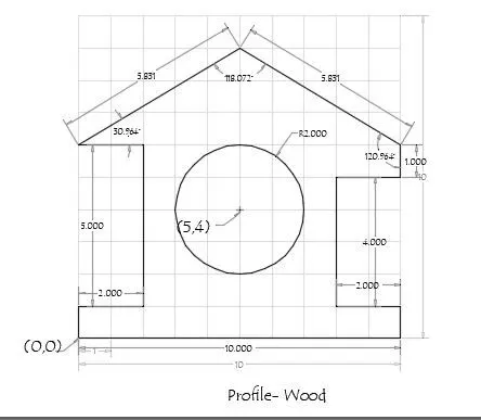
Steps of creating geometry in AutoCAD Software by Absolute coordination system:
- Open the AutoCAD application, Setup up the units to the imperial template and the decimal system.
- Set up the limits in the command tab using LIM before drafting.
- Type the command "L" for the line and specify
- Specify the first coordinates for starting point 1 (0,0)
- Specify next point 2 (10,0)
- Specify next point 3 ( 10,1)
- Specify next point 4 (8,1)
- Specify next point 5 (8,5)
- Specify next point 5 (10,5)
- Specify next point 7 (10,6)
- Specify next point 8 (5,9)
- Specify next point 9 (0,6)
- Specify next point 10 (2,6)
- Specify next point 11 (2,1)
- Specify next point 12 (0,1)
- Specify next point C
- Command: *Cancel*
- Type the command "C" for the circle and specify
- Specify the coordinate of the center of the circle as point 13 (5,4)
- Enter radius 2 in the command box.
- Specify next point C
- Command: *Cancel*
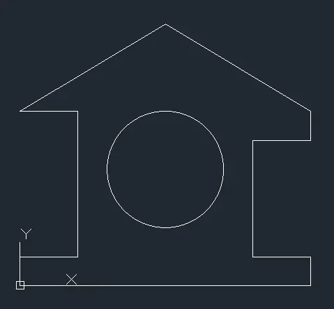
Result:
Procedure:
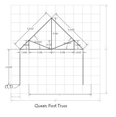
Steps of creating geometry in AutoCAD Software by Relative rectangular coordinate system:
- Type the command "L" for the line and specify
- Specify the first coordinates for starting point A (1,1)
- Specify next point B @0,4
- Specify next point C @1,0
- Specify next point D @2.536,0
- Specify next point E @2.536,0
- Specify next point F @1,0
- Specify next point G @0,-4
- Specify next point C
- Command: *Cancel*
- Type the command "L" for the line and specify
- Specify the first coordinates for starting point H ( pointer at D center of line then specify point for H @3.536,0).
- Then join the points H and B
- Command: *Cancel*
- Type the command "L" for the line and specify
- Then join the points H and F
- Command: *Cancel*
- Type the command "L" for the line and specify
- Specify the point I first placed at C to @ 0,1 (then join I and D points)
- Command: *Cancel*
- Type the command "L" for the line and specify
- Specify the point J first placed at E to @ 0,1 (then join J and E points)
- Command: *Cancel*
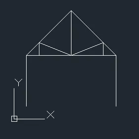
Result:
Procedure:
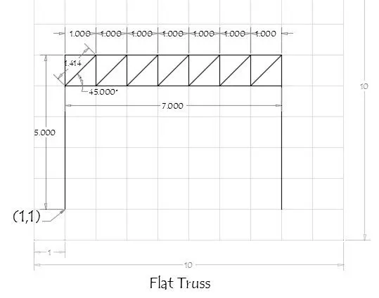
Steps of creating geometry in AutoCAD Software by Direct distance entry:
- Type the command "L" for the line and specify
- Specify the first coordinates for a starting point A (1,1)
- Line specify the next point B: 4 (Towards North)
- Line specify the next point C: 1 (Towards North)
- Line specify the next point D: 1 (Towards East)
- Line specify the next point E: 1 (Towards East)
- Line specify the next point F: 1 (Towards East)
- Line specify the next point G: 1 (Towards East)
- Line specify the next point H: 1 (Towards East)
- Line specify the next point I: 1 (Towards East)
- Line specify the next point J: 1 (Towards East)
- Line specify the next point K: 1 (Towards South)
- Line specify the next point L: 4 (Towards South)
- Specify next point C
- Command: *Cancel*
- Type the command "L" for the line and specify
- Specify the first coordinates for a starting point at K then forward 1 Towards West)
- Line specify the next point M: 1 (Towards West)
- Line specify the next point N: 1 (Towards West)
- Line specify the next point O: 1 (Towards West)
- Line specify the next point P: 1 (Towards West)
- Line specify the next point Q: 1 (Towards West)
- Line specify the next point R: 1 (Towards West) (Join the R and B points)
- Then join the B to D to R points, REQ, QFP, PGO, OHN, NIM, MJK.
- Specify next point C
- Command: *Cancel*
Result:
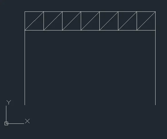
Procedure:
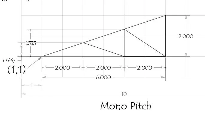
Steps of creating geometry in AutoCAD Software by Relative polar coordinate system:
- Type the command "L" for the line and specify
- Specify the first coordinates for a starting point A (1,1)
- Specify next point B @6<0
- Specify next point C @2<90
- Specify next point C
- Command: *Cancel*
- Type the command "L" for the line and specify
- Specify the first coordinates for a starting point D (3,1)
- Specify next point E @0.667<90
- Specify the point F (5,1) ( directly)
- Specify next point G @1.333<90 ( then join the G and B points directly)
- Specify next point C
- Command: *Cancel*
Result: