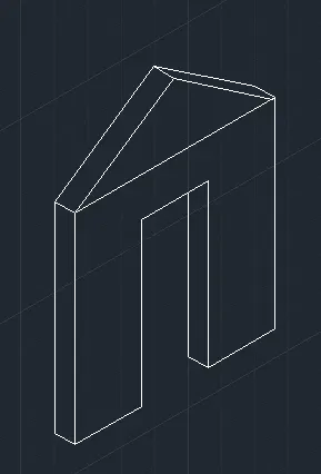
Creating a Floor plan, Footing detail and Isometric view using AutoCad
Aim: To create a C.S of the load-bearing wall overspread footing using AutoCad.
Step by Step Procedure:
- Open the AutoCAD application and Set up the units to the imperial template and the decimal system.
- Set up the limits in the command tab using LIM before drafting.
- Type the command "L" for the line and specify, Specify the first starting point
- Line specify the next point: 0.2 (Towards West) A-point
- Line specify the next point: 0.25 (Towards South)
- Line specify the next point: 0.9 (Towards East)
- Line specify the next point: 0.25 (Towards North)
- Line specify the next point: 0.2 (Towards West)
- Specify next point C 'close'
- Press Esc then Command: *Cancel*
- Type the command "L" for the line and specify, Specify the first starting point (put the cursor on the A-point)
- Line specify the next point: 0.4 (Towards North)
- Line specify the next point: 0.05 (Towards East)
- Line specify the next point: 0.4 (Towards North)
- Line specify the next point: 0.05 (Towards East)
- Line specify the next point: 0.3 (Towards East) B-point
- Line specify the next point: 0.05 (Towards East)
- Line specify the next point: 0.4 (Towards South)
- Line specify the next point: 0.05 (Towards East)
- Line specify the next point: 0.4 (Towards North)
- Specify next point C 'close'
- Press Esc then Command: *Cancel*
- Type the command "L" for the line and specify, Specify the first starting point (put the cursor on the B-point)
- Line specify the next point: 0.45 (Towards North)
- Line specify the next point: 0.15 (Towards North) C -point
- Line specify the next point: 0.05 (Towards North)
- Line specify the next point: 1 (Towards North)
- Line specify the next point: 0.3 (Towards East)
- Line specify the next point: 1 (Towards South)
- Line specify the next point: 0.05 (Towards South)
- Line specify the next point: 0.6 (Towards South)
- Line specify the next point: 1 (Towards East)
- Line specify the next point: 0.6 (Towards North)
- Line specify the next point: 1 (Towards West)
- Press Esc then Command: *Cancel*
- Type the command "L" for the line and specify, Specify the first starting point (put the cursor on the C-point)
- Line specify the next point: 0.3 (Towards West)
- Line specify the next point: 0.15 (Towards South)
- Line specify the next point: 0.3 (Towards West)
- Line specify the next point: 0.15 (Towards South)
- Line specify the next point: 0.3 (Towards West)
- Line specify the next point: 0.15 (Towards South)
- Line specify the next point: 0.3 (Towards West)
- Line specify the next point: 0.15 (Towards South)
- Line specify the next point: 1.15 (Towards East)
- Press Esc then Command: *Cancel*
- Type the command "DIMLIN" then specify the points do all over the mentioning dimensions of the over footing.
- Press Esc then Command: *Cancel*
Result:
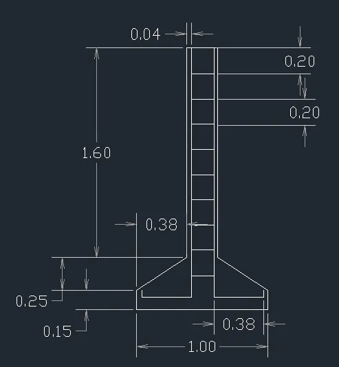
Aim: To create a C.S Isolated footing using AutoCad.
Step by Step Procedure:
- Open the AutoCAD application and Set up the units to the imperial template and the decimal system.
- Set up the limits in the command tab using LIM before drafting.
- Type the command "L" for the line and specify, Specify the first starting point
- Line specify the next point: 0.05 (Towards South)
- Line specify the next point: 0.38 (Towards East)
- Line specify the next point: 0.16 (Towards North)
- Line specify the next point: 0.17 (Towards East) A-point
- Line specify the next point: 0.16 (Towards South)
- Line specify the next point: 0.38 (Towards East)
- Line specify the next point: 0.05 (Towards North)
- Press Esc then Command: *Cancel*
- Type the command "L" for the line and specify, Specify the first starting point (placed the cursor at A point
- Line specify the next point: 0.20 (Towards North) B -point
- Line specify the next point: 0.17 (Towards East) C -point
- Line specify the next point: 0.20 (Towards South) D -point
- Press Esc then Command: *Cancel*
- Type the command "COPY" then select the objects BCD at once, press enter then select Mode - multiple
- Specify the base point at A-point then click on Array give 8 then specify the second point on point B
- Press Esc then Command: *Cancel*
- Type the command "L" for the line and specify, Specify the first starting point at top of the left side of the footing then specify the next point 0.04 the west towards.
- Line specify the next point: 1.60 (Towards South) E -point
- Line specify the next point: 0.38 (Towards West)
- Line specify the next point: 0.25 (Towards South)
- Line specify the next point: 0.15 (Towards South) F -point
- Line specify the next point: 1 (Towards East)
- Line specify the next point: 0.15 (Towards North) G -point
- Line specify the next point: 0.25 (Towards North)
- Line specify the next point: 0.38 (Towards West)
- Line specify the next point: 1.60 (Towards North) H-point
- Line specify the next point: 0.04 (Towards West)
- Press Esc then Command: *Cancel*
- Type the command "ERASE" then select the objects of both sides of line segments 0.38 & 0.25 then enter.
- Press Esc then Command: *Cancel*
- Type the command "L" for the line and specify, Specify the first starting point, join EF and GH.
- Press Esc then Command: *Cancel*
- Type the command "DIMLIN" then specify the points.
- Press Esc then Command: *Cancel*
Result:
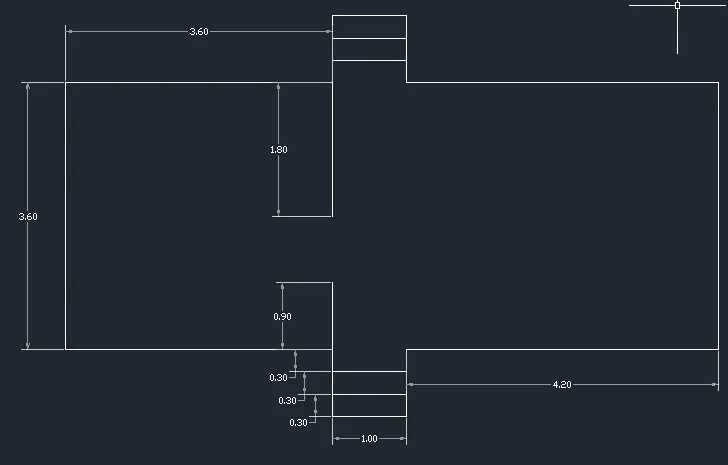
Aim: To create a Line diagram of a two-bedroom building using AutoCad.
Step by Step Procedure:
- Open the AutoCAD application and Set up the units to the imperial template and the decimal system.
- Set up the limits in the command tab using LIM before drafting.
- Type the command "L" for the line and specify, Specify the first starting point Notice it is A-Point
- Line specify the next point: 3.6 (Towards East) B-point
- Line specify the next point: 0.30 (Towards South) C-point
- Line specify the next point: 0.30 (Towards South) D-point
- Line specify the next point: 0.30 (Towards South) E-point
- Line specify the next point: 1 (Towards East)
- Line specify the next point: 0.30 (Towards North) F-point
- Line specify the next point: 0.30 (Towards North) G-point
- Line specify the next point: 0.30 (Towards North) H-point
- Line specify the next point: 4.2 (Towards East)
- Line specify the next point: 3.6 (Towards North)
- Line specify the next point: 4.2 (Towards West)
- Line specify the next point: 0.30 (Towards North) I-point
- Line specify the next point: 0.30 (Towards North) J-point
- Line specify the next point: 0.30 (Towards North) G-point
- Line specify the next point: 1 (Towards West)
- Line specify the next point: 0.30 (Towards South) K-point
- Line specify the next point: 0.30 (Towards South) L-point
- Line specify the next point: 0.30 (Towards South) M-point
- Line specify the next point: 3.6 (Towards West)
- Specify next point C 'close'
- Press Esc then Command: *Cancel*
- Type the command "L" for the line and specify, Specify the first starting point 0.9 at A-Point towards the North
- Press Esc then Command: *Cancel*
- Type the command "L" for the line and specify, Specify the first starting point 1.8 at G-Point towards the South
- Press Esc then Command: *Cancel*
- Type the command "L" for the line and specify, Specify the first starting point join the points of CH, DG, EF, then IM, JL, GK.
- Press Esc then Command: *Cancel*
- Type the command "DIMLIN" then specify the points
- Press Esc then Command: *Cancel*
Result:
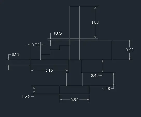
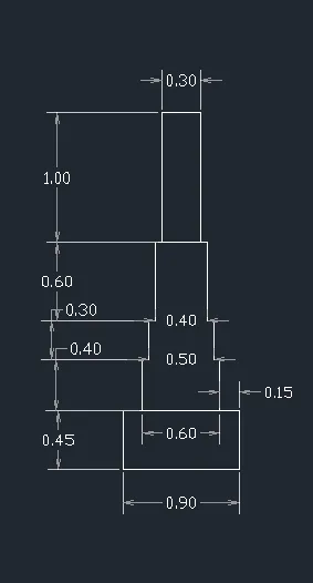
Aim: To create a Line diagram of C.S of load-bearing wall showing foundation using AutoCad.
Step by Step Procedure:
- Open the AutoCAD application and Set up the units to the imperial template and the decimal system.
- Set up the limits in the command tab using LIM before drafting.
- Type the command "L" for the line and specify, Specify the first starting point
- Line specify the next point: 0.15 (Towards West) A-point
- Line specify the next point: 0.45 (Towards South)
- Line specify the next point: 0.90 (Towards East)
- Line specify the next point: 0.45 (Towards North)
- Line specify the next point: 0.15 (Towards West) B-point
- Line specify the next point: 0.40 (Towards North)
- Line specify the next point: 0.05 (Towards West)
- Line specify the next point: 0.30 (Towards North)
- Line specify the next point: 0.05 (Towards West)
- Line specify the next point: 0.60 (Towards North)
- Line specify the next point: 0.05 (Towards West) C -point
- Line specify the next point: 1 (Towards North)
- Line specify the next point: 0.3 (Towards West)
- Line specify the next point: 1 (Towards South)
- Line specify the next point: 0.05 (Towards West) D- point
- Line specify the next point: 0.6 (Towards South)
- Line specify the next point: 0.05 (Towards West)
- Line specify the next point: 0.30 (Towards South)
- Line specify the next point: 0.05 (Towards West)
- Line specify the next point: 0.40 (Towards South)
- Press Esc then Command: *Cancel*
- Type the command "L" for the line and specify, Specify the first starting point (join the points of AB)
- Press Esc then Command: *Cancel*
- Type the command "L" for the line and specify, Specify the first starting point (join the points of CD)
- Press Esc then Command: *Cancel*
- Type the command "DIMLIN" then specify the points
- Press Esc then Command: *Cancel*
Result:
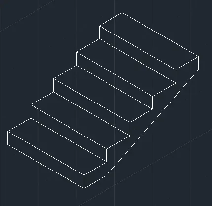
Aim: To create an Isometric view of steps using AutoCad.
Step by Step Procedure:
- Open the AutoCAD application and Set up the units to the imperial template and the decimal system.
- Set up the limits in the command tab using LIM before drafting.
- Type the Command: <Grid on>
- Type the Command: _.ISODRAFT Enter an option [Orthographic/isoplane Left/isoplane Top/isoplane Right] <Orthographic>: <Isoplane Right>
- Type the command "L" for the line and specify, Specify the first starting point (take it A-point)
- Line specify the next point: 0.15 (Towards South) (take it as B-point)
- Line specify the next point: <Isoplane Top> 1 (Towards West)
- Line specify the next point: <Isoplane Left> 0.15 (Towards North)
- Line specify the next point: <Isoplane Right> 0.3 (Towards east)
- Line specify the next point: <Isoplane Right> 0.15 (Towards North) (take it as C-point)
- Line specify the next point: 0.3 (Towards east) (take it as an I -point)
- Line specify the next point: 0.15 (Towards North) (take it as a K -point)
- Line specify the next point: 0.3 (Towards east) (take it as an M -point)
- Line specify the next point: 0.15 (Towards North) (take it as an O -point)
- Line specify the next point: 0.3 (Towards east) (take it as a Q -point)
- Line specify the next point: 0.15 (Towards North) (take it as an S -point)
- Line specify the next point: 0.3 (Towards east) (take it as F- point)
- Line specify the next point: 0.15 (Towards South) (take it as D-point)
- Press Esc then Command: *Cancel*
- Type the command "L" for the line and specify, Specify the first starting point (placed the cursor at B-point)
- Line specify the next point: 0.3 (Towards east) (take it as E-point) then (Join the E and D points )
- Press Esc then Command: *Cancel*
- Type the command "L" for the line and specify, Specify the first starting point ( put the cursor at C-point)
- Line specify the next point: <Isoplane Top> 0.3 (Towards east) (take it as an H -point)
- Line specify the next point: 0.15 (Towards North) (take it as a J -point)
- Line specify the next point: 0.3 (Towards east) (take it as an L -point)
- Line specify the next point: 0.15 (Towards North) (take it as an N -point)
- Line specify the next point: 0.3 (Towards east) (take it as a P -point)
- Line specify the next point: 0.15 (Towards North) (take it as an R -point)
- Line specify the next point: 0.3 (Towards east) (take it as a U -point)
- Line specify the next point: 0.15 (Towards North)
- Line specify the next point: 0.3 (Towards east) (take it as G- point) then join the G and F
- Press Esc then Command: *Cancel*
- Type the command "L" for the line and specify, Specify the first starting point ( put the cursor at C-point)
- By the using Line command join the points of IJ, KL, MN, OP, QR, SU
- Press Esc then Command: *Cancel*
- Type the command "DIMLIN" then specify the points.
- Press Esc then Command: *Cancel*
Result:
Aim: To create an Isometric view of the Gable wall using AutoCad.
Step by Step Procedure:
- Open the AutoCAD application and Set up the units to the imperial template and the decimal system.
- Set up the limits in the command tab using LIM before drafting.
- Type the Command: <Grid on>
- Type the Command: _.ISODRAFT Enter an option [Orthographic/isoplane Left/isoplane Top/isoplane Right] <Orthographic>: <Isoplane Right>
- Type the command "L" for the line and specify, Specify the first starting point (take it A-point)
- Line specify the next point: 3 (Towards North) (take it as a B -point)
- Line specify the next point: 0.25 (Towards North) (take it as an E -point)
- Line specify the next point: 1.5 (Towards East) (take it as a C -point)
- Line specify the next point: 1.5 (Towards East)
- Line specify the next point: 0.25 (Towards South) (take it as an F -point)
- Line specify the next point: 3 (Towards South) (take it as a D -point)
- Line specify the next point: 1 (Towards West) (take it as a Q -point)
- Line specify the next point: 2.42 (Towards North)
- Line specify the next point: 1 (Towards West)
- Line specify the next point: 2.42 (Towards South)
- Line specify the next point: 1 (Towards West)
- Press Esc then Command: *Cancel*
- Type the command "L" for the line and specify, Specify the first starting point (put the cursor at B-point then join to the C -point then join to the point D
- Press Esc then Command: *Cancel*
- Type the Command: ERASE select the objects (erase the line segments of EC and FC)
- Press Esc then Command: *Cancel*
- Type the command "L" for the line and specify, Specify the first starting point (put the cursor at A-point )
- Line specify the next point: <Isoplane Left> 0.30(Towards West ) (take it as a G -point)
- Press Esc then Command: *Cancel*
- Type the command "L" for the line and specify, Specify the first starting point (put the cursor at B-point )
- Line specify the next point: <Isoplane Left> 0.30(Towards West ) (take it as an H -point)
- Press Esc then Command: *Cancel*
- Type the command "L" for the line and specify, Specify the first starting point (put the cursor at C-point )
- Line specify the next point: <Isoplane Left> 0.30(Towards West ) (take it as an I -point)
- Press Esc then Command: *Cancel*
- Type the command "L" for the line and specify, Specify the first starting point (put the cursor at D-point )
- Line specify the next point: <Isoplane Left> 0.30(Towards West ) (take it as a J -point)
- Press Esc then Command: *Cancel*
- Type the command "L" for the line and specify, Specify the first starting point (put the cursor at G-point then join to the points of H, I, and, J
- Press Esc then Command: *Cancel*
- Type the command "L" for the line and specify, Specify the first starting point (put the cursor at Q-point)
- Line specify the next point: <Isoplane Left> 0.30(Towards West ) (take it as a P -point)
- Line specify the next point: <Isoplane Left> 2.42(Towards North )
- Press Esc then Command: *Cancel*
Result: