Creation of Column Schedule and Drawing Template using AutoCad
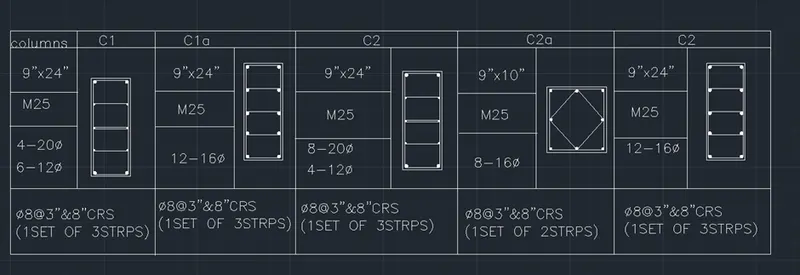
1.AIM: Create a column schedule as shown in the figure.
Note: Create a column schedule with the help of lines. Also, insert text with the help of Dtext command or Single Line text.
Hint: Use font name: romans.shx; Height: 8”, Justify: Left
- SOFTAWARE USED : AUODESK AUTOCAD 2021
- PROCEDURE :
- first the open the software
- give the command QNEW and press the ENTERE key
- click on imperical templete
- select ADVANCE SETUP
- unit : Engineering, precision :0.00
- angle :decimal degree , precision :0.00
- angle measure : East
- angle direction : closkwise
- area : 20*20
- and finished , lets start
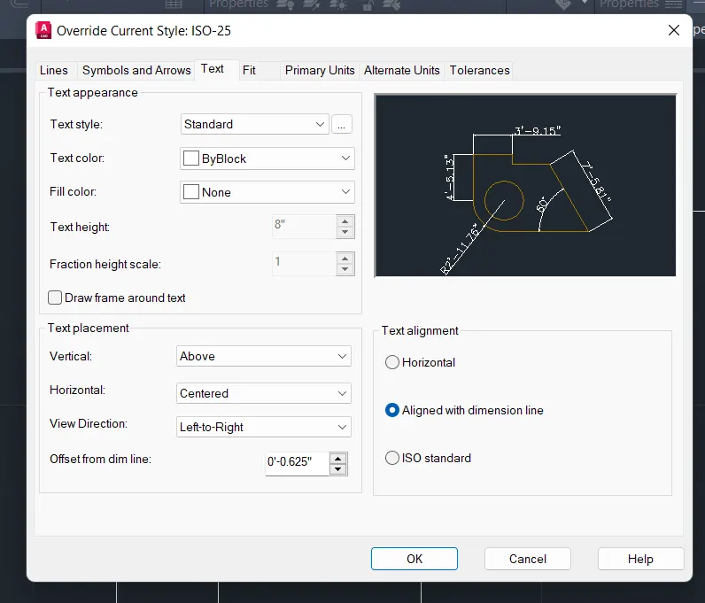
- command : D (dimension style manager )
- click on :MODIFY
- select : TEXT option
- selct text style : romanc.shx
- command : dt (for text )
- select start point
- height : 8"
- angle :0
- justify : left
- press : ENTER
- prepare a table and write all texts in table
- go to the layer properties
- create two layers
- for table
- colour : cyan
- for text
- colour: yellow
- command : REC ( for rectangle )
- press : ENTER
- COMMAND : o (for ofset )
- distance : 3"
- command :c (for circle )
- mode : tan, tan, radius
- select two tangent
- radius :1"
- command : MI (for mirror )
- mirror this circle
- command :x (for explode )
- select the object
- press : ENTER
- Command : divide
- select the line
- segment :4
- copy and circle and place the center and mirror it
- command : DO ( For donut )
- internal diameter :0
- outer diameter :2
- press enter
- command : L (for line )
- and draw the links of columns
RESULTS :
- Window Schedule:
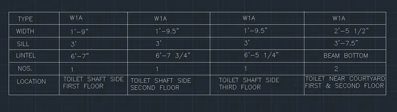
Aim: to draw the window schedule
Procedure:
- First we create a table of length 50' and width 12' by using rectangle command.
- Divide the 50' line into 5 equal parts of 10' each.
- By using offset command we create 6 rows.
- Divide the 12' line into 6 equal parts of 2' each.
- By using offset command we create 5 columns.
- Now we insert the text:
- Select single line from the text drop down menu.
- Specify start point of text: specify the point where we need to start the text.
- Specify text height and give 8".
- Specify the rotation angle of text and give it as 0 degree.
- Type the text we need to insert.
- For changing the text style we use command "ST". Font selected is "roman.shx".
- To change the properties of text, right click-properties,we can edit the properties we want.
- Enter"TYPE","WIDTH","SILL","NO","LOCATION" in the 1st column and W1 A,W2 in the rows.
- We can copy the text and use edit option to change the text by "CO" command.
- Enter the values given in the table,for fractional numbers enter the multiline text option.
- Use grips to adjust the text box width and height to fit in the column.
Result: window schedule is drawn.
- Creating template:
Aim: to create the template
Procedure:
- First we create the table by drawing a rectangle of length 40' and width 15'.
- Copy this rectangle and place it next to it with snap on and copy 2 of them.
- Using the copy command select the object and select the base point and select the point where we need to place the rectangle.
- Divide the 2nd column of table into two and 3rd column into 5.
- By using the offset command:with offset distance 3' select the object and create the rows.
- Divide the 3rd column into 4 each of 10' by offset command and trim off the extra lines.
- Now we insert the text:
- Select the multi line fron drop down list of text -create the text box and type tha given data.
- Text height is given as 8"
Result: The template drawn is shown.
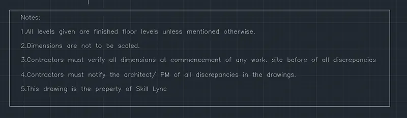
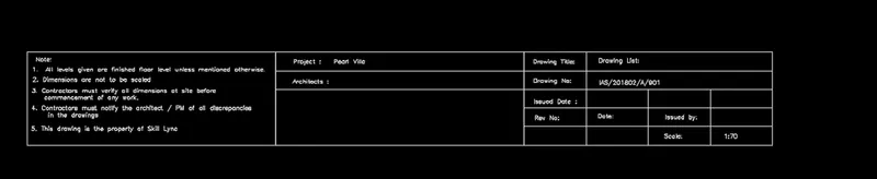
- List of drawing schedule:
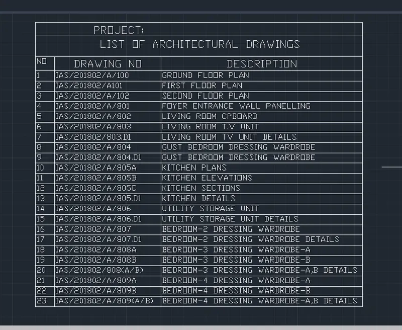
Aim: to create the list of drawings schedule.
Procedure:
- Draw a rectangle of length 102' andwidth 83' using the rectangle command.
- Draw the columns by offset command witha distance of 10',32',60" from the left side.
- Create rows by offsetting a distance of 3',5',3' from the top side.
- Trim off the extra line using trim command.
- Now we insert heading texts:
- With multiline option from the text drop down menu,create a text box in the 1st row and type"project" with text height 1'-8" and style as romas.shx
- In the second row,using mutliline text tyoe"LIST OF ARCHITECTURAL DRAWING" with text height of 2'-1" and same style.
- In the 3rd row change the height to 1'8" and same style.
- Now we create the rows:
- With offset command create rows of height 3', offset distance of 3' and create 24 such rows.
- Now inserting text:
- Select multiline text and create the text box with text heught 1'8" and type the data given in each rows and columns.
- In the column nos type the numbers from 1 to 24.
- In drawing no: column type the first entity,the use copy command select teh object,select array the enter the number of items in array as 23 and then click on the point where we need to place the array.
Result: The list of drawing schedule is created.
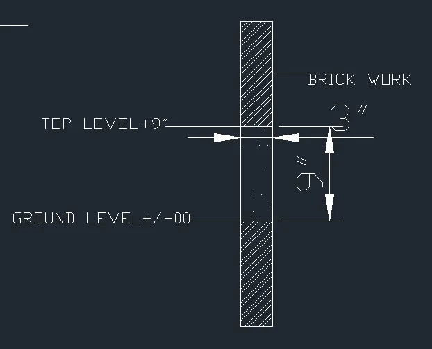
- Beam detail:
Aim: to draw the beam detail
Procedure:
- Draw a cross-section of beam with height 4' and thickness 9"
- With line command draw a line of 4' in +y direction then 9" in + x direction and 4' downwards and close.
- From the top give an offset of 9" which marks the ground level using the offset command by giving distance as 9".
- Then give an offset of 3" from 9" line.Give an offset distance of 3" which indicate the bottom level of concrete.
- Hatch the portion of brick and concret and trim off the line of ground level fro the cross-section of the beam.
- Now we insert the text:
- Select the multi leader from the annotate tab and write the text with text height of 2".
- Type the text"TOP LEVEL +9" at the top of 9" line,type "GROUND LEVEL+/-00" At the 3" ground line.
- Type "BRICKWORK" indicating the part of brickwork using multileader.
- With the multiline text from the text dropdown type "SECTION 1" at bottom of the figure at 2" height.
Result: the beam detail is drawn.